D-Link D-Link DGS-1026MP 26-Port Unmanaged Poe Switch User manual

Category
Network switches
Type
User manual

This manual is also suitable for

D-Link DGS-1026MP 26-Port Unmanaged PoE Switch is a versatile networking solution for expanding your network and connecting PoE-powered devices. With 24 Gigabit PoE ports and 2 Gigabit combo uplink ports, it provides ample connectivity options for various devices such as IP cameras, VoIP phones, and wireless access points. Its PoE capability allows you to power these devices without the need for separate power adapters, simplifying installation and reducing cable clutter.

D-Link DGS-1026MP 26-Port Unmanaged PoE Switch is a versatile networking solution for expanding your network and connecting PoE-powered devices. With 24 Gigabit PoE ports and 2 Gigabit combo uplink ports, it provides ample connectivity options for various devices such as IP cameras, VoIP phones, and wireless access points. Its PoE capability allows you to power these devices without the need for separate power adapters, simplifying installation and reducing cable clutter.

i
Table of Contents
About This Guide ............................................................................................................................................. 1
Terms/Usage .................................................................................................................................................. 1
Copyright and Trademarks ............................................................................................................................ 1
Product Introduction ....................................................................................................................................... 2
Package Contents .......................................................................................................................................... 2
Product Overview ........................................................................................................................................... 2
Front Panel ................................................................................................................................................. 2
Rear Panel .................................................................................................................................................. 2
Indicator LEDs ............................................................................................................................................ 3
Hardware Installation ...................................................................................................................................... 4
Installation Precautions .................................................................................................................................. 4
Grounding the Switch ..................................................................................................................................... 4
Attaching the Rubber Feet ............................................................................................................................. 4
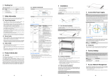
Mounting the Switch in a Rack ....................................................................................................................... 5
Powering on the Switch.................................................................................................................................. 6
Connect to an End Node ............................................................................................................................ 6
Connect to a Hub or Switch ........................................................................................................................ 7
Connect to a Network Backbone or Server ................................................................................................ 7
Understanding the Switch’s Features ........................................................................................................... 8
Power Over Ethernet (PoE) ........................................................................................................................... 8
Hardware Specifications ................................................................................................................................ 9
Key Components / Performance ................................................................................................................ 9
Ports ........................................................................................................................................................... 9
Port Standards ............................................................................................................................................ 9
Physical & Environment ............................................................................................................................. 9
Emission (EMI) Certifications ..................................................................................................................... 9
Safety Certifications.................................................................................................................................... 9
Features ......................................................................................................................................................... 9
General Features........................................................................................................................................ 9
PoE Features .............................................................................................................................................. 9
Appendix B - Regulatory Statements .......................................................................................................... 10
1
About This Guide
This guide provides instructions to install the D-Link DGS-1026MP 26-Port Unmanaged PoE Switch.
Terms/Usage
In this guide, the term “Switch” (first letter capitalized) refers to the DGS-1026MP, and “switch” (first letter lower
case) refers to other Ethernet switches. Some technologies refer to the terms “switch”, “bridge” and “switching
hubs” interchangeably, and all are commonly accepted for Ethernet switches.
A NOTE indicates important information to use
the device properly.
A CAUTION indicates potential property damage
or personal injury.
Copyright and Trademarks
Information in this document is subjected to change without notice.
© 2021 D-Link Corporation. All rights reserved.
Reproduction in any manner whatsoever without the written permission of D-Link Corporation is strictly
forbidden.
Trademarks used in this text: D-Link and the D-LINK logo are trademarks of D-Link Corporation.
Other trademarks and trade names may be used in this document to refer to either the entities claiming the
marks and names or their products. D-Link Corporation disclaims any proprietary interest in trademarks and
trade names other than its own.
2
Product Introduction
The DGS-1026MP is an unmanaged switch with 24 10/100/1000 Mbps ports and 2 Gigabit combo uplink ports.
The first 24 10/100/1000 Mbps ports of the DGS-1026MP support IEEE 802.3af/at Power over Ethernet (PoE)
and are capable of supplying up to 30 watts of power per port. The DGS-1026MP is easy to install and requires
no configuration. With these features combined, the DGS-1026MP provides an ideal solution for Small and
Medium Business (SMB) users who have limited budgets but require PoE capability in a switch.
Package Contents
Open the shipping carton and carefully unpack the contents. Please consult the packing list to make sure all
items are present and undamaged.
One D-Link DGS-1026MP 26-Port Unmanaged PoE Switch
One power cord
One power cord retainer
One rack-mount kit and rubber feet
One Quick Start Guide
If any item is found missing or damaged, please contact your local retailer for replacement.
Product Overview
Front Panel
Figure DGS-1026MP Front Panel
Item Description
LED MODE Press to change the port LEDs to display the PoE status or the link status. The color of
the LED Mode light will indicate which LED status display is currently active. Green LEDs
means the Switch is currently showing the Link/Act/Speed status of the ports, while
amber LEDs display the PoE status of the ports. Please refer to the table in the section
Indicator LEDs for more detailed information on the LED Mode function.
Ports 1 to 24 These are 10/100/1000 Mbps PoE-capable ports used for connecting Ethernet devices
and PoE-powered devices.
Ports 25 to 26 These are 1000 Mbps/SFP combo ports. When using one interface of these combo
ports, the other interface in the pair will become unavailable. For example, using the SFP
interface on port 25 will render the RJ45 interface on port 25 unavailable.
Table 1 Front panel connector description
Rear Panel
Figure 1 – DGS-1026MP Rear Panel
3
Item Description
Kensington
Security Lock
The DGS-1026MP adds additional value by providing users with a simple, reliable, built-
in security solution to prevent theft in the form of a Kensington Security Slot on the rear
panel of the Switch.
SWITCH GND This is used to connect the switch to ground.
Power Cord
Retainer Slot
This is used for securing the power cord retainer to the switch.
AC Power
Connector
The AC power cord (included in the package) can be plugged into this receptacle
to supply the switch with 100-240 VAC power at 50-60 Hz.
Table 2 Rear panel connector description
Indicator LEDs
Figure 3 – DGS-1026MP Front panel LEDs
LED Status Description
PoE Power
Budget Solid red (LED above “300W”) The total PoE power consumption is between 301
and 370 W
Solid amber (LED below “300W”) The total PoE power consumption is between 201
and 300 W.
Solid green (LED below “200W”) The total PoE power consumption is between 101
and 200 W.
Solid green (LED below “100W”) The total PoE power consumption is between 1 and
100 W.
Off There are no PoE-powered devices connected to the switch.
LED Mode Solid amber The port LEDs are currently displaying the PoE status. Please refer to
PoE Mode in this table for more information.
Solid green The port LEDs are currently displaying the port link status. Please refer
to Link Mode in this table for more information.
Power Solid green The device is powered on.
PoE Mode
(Ports 1 to 24)
Solid amber The power supply on the corresponding port has failed.
Solid green The corresponding port is supplying power correctly.
Link Mode
(port1~24)
Solid green There is an active link on the corresponding port at 1000 Mbps.
Blinking
green Reception or transmission at 1000Mbps
Solid amber There is an active link on the corresponding port at 10/100 Mbps.
Blinking
amber There is traffic on the corresponding port at 10/100 Mbps.
Link Mode
(port25~26)
Solid green There is an active link on the corresponding port at 1000 Mbps.
Blinking
green Reception or transmission at 1000Mbps
Table 3Front panel LED description
4
Hardware Installation
This chapter provides more detailed instructions for grounding and installing the DGS-1026MP.
Installation Precautions
For safe installation and operation of the Switch, it is recommended to:
Visually inspect the DC power jack and make sure that it is fully secured to the power adapter.
Make sure that there is at least 10 cm of space on each side of the Switch to allow for proper heat
dissipation and adequate ventilation around the Switch.
Install the Switch in a site free from strong electromagnetic sources, vibration, dust, and direct
sunlight.
Install the Switch in a cool and dry place. Refer to the technical specifications section of this manual
for the acceptable operating temperature and humidity ranges.
Not place heavy objects on the Switch.
.
Grounding the Switch
This section describes how to connect the Switch to ground. It is necessary to complete this procedure before
powering on the Switch.
Required Tools and Equipment
One ground screw (this Switch is shipped with this screw already in place on the rear panel of the device).
Ground cable (not included in the accessory kit): The grounding cable should conform to local and national
installation requirements. Commercially available 18 AWG wire is recommended. The length of the cable
depends on the proximity of the Switch to proper grounding facilities.
A screwdriver (not included in the accessory kit).
The following steps explain the procedure for connecting the Switch to a protective ground:
1. Verify that the Switch is powered off.
2. Remove the grounding screw marked SWITCH GND from the back of the device and place the #8
terminal lug ring of the grounding cable on top of the ground screw opening, as seen in the figure below.
3. Insert the grounding screw back into the ground screw opening.
4. Using a screwdriver, tighten the ground screw to secure the ground cable to the Switch.
5. Attach the terminal lug ring at the other end of the grounding cable to an appropriate grounding source.
6. Verify that the connection from the ground connector on the Switch to the ground source is secure.
Figure 4 – Attaching a grounding cable
Attaching the Rubber Feet
The DGS-1026MP comes with a strip of four adhesive rubber pads that can be placed on the bottom of the
device to prevent the Switch from damaging the surface it is placed on. This allows the Switch to be placed
5
virtually anywhere. To attach the rubber pads, simply remove them from the adhesive strip and stick one pad
on each corner on the bottom panel of the Switch.
Figure 5 - Attaching the rubber feet
Mounting the Switch in a Rack
The DGS-1026MP can be easily mounted in a rack using the two provided mounting brackets. Make sure that
the front panel is exposed in order to view the LEDs. Please refer to the following illustrations:
1. Attach and fasten the rack mounting brackets to each side of the Switch using the included screws.
Figure 6 - Attaching the rack brackets
2. Firmly secure the brackets with the Switch to the rack. Please follow the usual safety precautions for rack-
mountable products.
Figure 7 - Securing the Switch to a rack
6
Powering on the Switch
To power on the Switch, connect the provided power cable to the power socket on the back of the Switch, and
connect the adapter side of the cord to a suitable power source.
After the Switch has been powered on, the LED indicators will blink briefly while the system initializes.
As a precaution, in the event of a power failure it is recommended to unplug the Switch. When power has been
restored, plug the Switch back in.
Connect to an End Node
Use a standard Ethernet cable to connect the Switch to PCs with a 10/100/1000 Mbps RJ45 interface, or
connect and power remote IEEE 802.3af/at-compliant PoE devices, such as IP cameras or IP phones. The
Switch ports will automatically adjust to the hardware characteristics (MDI/MDIX, speed, duplex mode) of the
connected device.
Figure 8 – Connecting the Switch to a node
7
Connect to a Hub or Switch
Use a straight or crossover cable to connect the Switch to another switch or hub.
Figure 9 – Connecting the Switch to another switch or hub
Connect to a Network Backbone or Server
Use any port on the device to connect the Switch to a network backbone or network server. When linking to
a 1000BASE-T device, the port operates in full-duplex mode.
Figure 10Connecting the Switch to another switch or hub
8
Understanding the Switch’s Features
Power Over Ethernet (PoE)
The DGS-1026MP supports many PoE features to guarantee the safety and stability of the Switch and the
connected powered devices.
PoE Power Budget: The total PoE budget of the DGS-1026MP is limited to a maximum of 370 watts to both
protect the Switch and to stabilize the power being transmitted to the PoE-powered devices.
Guard Band: The DGS-1026MP reserves a 7 watts Guard Band to prevent the PoE power supply from
exceeding the maximum PoE power budget of 370 watts. When the Switch detects the current PoE output has
reached the maximum of 370 watts, and another device is connected to the Switch, the Switch will check which
type of device is being connected. If the device is another PoE-powered device, the Switch will disconnect the
power on the port with the higher port number in order to power the new device.
PWM Fan Speed Control
The DGS-1026MP supports PWM fan speed control. The fan speeds range from 20% to 100%, with a
maximum speed of 9000rpm and a minimum speed of 2000rpm. The speed regulation of the fan is related to
the PD load power and is set to 5 speeds. Through the coordination of PD load power and fan speed, the
balance between noise and thermal is achieved.
PD Load Fan Speed
0-60W 2000rpm
90W 3000rpm
120-180W 6750rpm
210-270W 8250rpm
300-370W 9000rpm
9
Appendix A - Technical Specifications
Hardware Specifications
Key Components / Performance
Switching Capacity: 52 Gbps
Max. Forwarding Rate: 38.69 Mpps
Forwarding Mode: Store-and-forward
Packet Buffer memory: 512 Kbytes
Ports
24 x 10/100/1000BASE-T PoE ports
2 x 1000BASE-T/SFP combo ports
Port Standards
IEEE 802.3
IEEE 802.3u
IEEE 802.3x (Full-duplex Flow Control)
IEEE 802.3z
IEEE 802.3af/at (ports 1 to 24)
Physical & Environment
Dimensions: 440 x 267 x 44 mm
Weight: 3.95 kg
Internal Power Supply AC input: 100~240
VAC, 50/60Hz
Acoustic: 46.89 dB(A) at low speed, 51.9
dB(A) at high speed
Operation Temperature: 0 to 50 °C
Storage Temperature: -40 to 70 °C
Operation Humidity: 0% to 95% RH
Storage Humidity: 0% to 95% RH
Emission (EMI) Certifications
CE
FCC
VCCI
BSMI
Safety Certifications
UL
CB
LVD
BSMI
Features
General Features
Surge protection
Supports up to 8K MAC addresses
PoE Features
IEEE 802.3af/at compliant
Supplies up to 30 watts power per port.
Total PoE budget: 370 watts.
10
Appendix B - Regulatory Statements
FCC Warning
This equipment has been tested and found to comply with the regulations for a Class A digital device, pursuant
to Part 15 of the FCC Rules. These limits are designed to provide reasonable protection against harmful
interference when the equipment is operated in a commercial environment. This equipment generates, uses,
and can radiate radio frequency energy and, if not installed and used in accordance with this user’s guide, may
cause harmful interference to radio communications. Operation of this equipment in a residential area is likely
to cause harmful interference, in which case the user will be required to correct the interference at his/her own
expense.
Innovation, Science and Economic Development Canada (ISED) Statement
This Class A digital apparatus complies with Canadian ICES-003. Cet appareil numérique de la classe A est
conforme à la norme NMB-003 du Canada.
VCCI Warning
UL Warning
a) Elevated Operating Ambient Temperature- If installed in a closed or multi-unit rack assembly, the operating
ambient temperature of the rack environment may be greater than room ambient. Therefore, consideration
should be given to installing the equipment in an environment compatible with the manufacturer's maximum
rated ambient temperature (Tmra).
b) Reduced Air Flow- Installation of the equipment in a rack should be such that the amount of air flow required
for safe operation of the equipment is not compromised.
c) Mechanical Loading- capitalize of the equipment in the rack should be such that a hazardous condition is
not achieved due to uneven mechanical loading.
d) Circuit Overloading- Consideration should be given to the connection of the equipment to the supply circuit
and the effect that overloading of circuits might have on over current protection and supply wiring. Appropriate
consideration of equipment nameplate ratings should be used when addressing this concern.
e) Reliable Earthing- Reliable earthing of rack-mounted equipment should be maintained. Particular attention
should be given to supply connections other than direct connections to the branch circuit (e.g., use of power
strips).
f) The Installation instructions clearly state that the ITE is to be connected only to POE networks without routing
to the outside plant.
BSMI statement
警告使用者: 此為甲類的資訊技術設備,在居住環境中使用時,可能會造成射頻擾動,在這種情況下,使用者
會被要求採取某些適當的對策。
Warning:
This is a class A product. In a domestic environment this product may cause radio interference in which case
the user may be required to take adequate measures.
Fuse is in the neutral, and that the mains shall be disconnected to de-energize the phase conductors.
This is for power supply: POE-U400D54+12D
CAUTION
DOUBLE POLE/NEUTRAL FUSING
Attention
Fusion bipolaire / neuter
11
CE Mark Warning
This equipment is compliant with Class A of CISPR 32. In a residential environment, this equipment may
cause radio interference.
Avertissement Concernant la Marque CE
Cet équipement est conforme à la classe A de la norme CISPR 32. Dans un environnement résidentiel, cet
équipement peut provoquer des interférences radio
iii
  • Page 1 1
  • Page 2 2
  • Page 3 3
  • Page 4 4
  • Page 5 5
  • Page 6 6
  • Page 7 7
  • Page 8 8
  • Page 9 9
  • Page 10 10
  • Page 11 11
  • Page 12 12
  • Page 13 13
  • Page 14 14
  • Page 15 15
  • Page 16 16

D-Link D-Link DGS-1026MP 26-Port Unmanaged Poe Switch User manual

Category
Network switches
Type
User manual
This manual is also suitable for

D-Link DGS-1026MP 26-Port Unmanaged PoE Switch is a versatile networking solution for expanding your network and connecting PoE-powered devices. With 24 Gigabit PoE ports and 2 Gigabit combo uplink ports, it provides ample connectivity options for various devices such as IP cameras, VoIP phones, and wireless access points. Its PoE capability allows you to power these devices without the need for separate power adapters, simplifying installation and reducing cable clutter.

Ask a question and I''ll find the answer in the document

Finding information in a document is now easier with AI