Page is loading ...

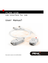
PCAN-AU5790
Bus Converter High-speed CAN
to Single-wire CAN
User Manual
Document version 2.2.0 (2019-05-20)

PCAN-AU5790 – User Manual
2
Relevant products
Product Name Model Part number
PCAN-AU5790 IPEH-002040
PCAN® is a registered trademark of PEAK-System Technik GmbH. CANopen® and
CiA® are registered community trade marks of CAN in Automation e.V.
All other product names mentioned in this document may be the trademarks or
registered trademarks of their respective companies. They are not explicitly marked
by “™” and “®”.
© 2019 PEAK-System Technik GmbH
PEAK-System Technik GmbH
Otto-Roehm-Strasse 69
64293 Darmstadt
Germany
Phone: +49 (0)6151 8173-20
Fax: +49 (0)6151 8173-29
www.peak-system.com
info@peak-system.com
Doc
ument version 2.2.0 (2019-05-20)

PCAN-AU5790 – User Manual
3
Contents
1 Introduction 4
1.1 Properties at a Glance 4
1.2 Scope of Supply 5
2 Connectors 6
2.1 D-Sub Socket: High-speed CAN, Primary Voltage
Supply 6
2.1.1 Supply Voltage V
main
6
2.1.2 Voltage Supply Alternatively Via Pin 9 7
2.1.3 Termination High-Speed-CAN 8
2.2 D-Sub Plug: Single-wire CAN, Secondary
Voltage Supply 9
2.2.1 Ground Connection (GND) 9
2.2.2 Additional Supply Voltage V
aux
9
2.2.3 Termination Single-wire CAN 9
3 Operation 10
3.1 Status LEDs 10
3.2 Single-wire CAN Operation Modes 10
3.2.1 Normal Mode 11
3.2.2 High-speed Mode 11
3.2.3 Wake-up Mode 11
3.3 CAN Bit Rate 12
4 Technical Specifications 13
Appendix A CE Certificate 15
Appendix B Dimension Drawing 16
Appendix C Quick Reference 17

PCAN-AU5790 – User Manual
4
1 Introduction
Tip: At the end of this manual (Appendix C) you can find a
Quick Reference with brief information about the installation
and operation of the PCAN-AU5790.
The bus converter PCAN-AU5790 establishes a connection between
a High-speed CAN bus (ISO 11898-2) and a Single-wire CAN bus
(SAE J2411). It is designed for direct connection of a CAN interface
of the PCAN series (e.g. PCAN-USB) to a Single-wire CAN bus. The
term AU5790 refers to the transceiver of the same name. This (or a
compatible transceiver) is used in the bus converter for the
connection to the Single-wire CAN bus.
Single-wire CAN
Single-wire CAN only uses one signal line in contrast to High-speed
CAN. Single-wire CAN is used in motor vehicles. The bodywork
functions as ground of the bus. Therefore the Single-wire CAN bus
actually consists of an unipolar line and thus reduces the overhead
of the wiring through the motor vehicle. On the other hand the
highest possible transmission rate is considerably lower than for
High-speed CAN.
1.1 Properties at a Glance
There are three operation modes for the SW-CAN side which
can be set using a sliding switch. Normal (33.3 kbit/s),
High-speed (83.3 kbit/s) and Wake-up
Indicator LEDs for power supply (red) and wake-up signals
(yellow)

PCAN-AU5790 – User Manual
5
Power supply (5 V, 150 mA) through High-speed CAN
connection (a current list of PEAK CAN interfaces with suitable
supply voltage is available on request)
If the power supply has a lower current output than 150 mA, an
additional 12-Volt supply is needed via Single-wire CAN
connector
Operating temperature range from 0 to 70 °C (32 to 185 °F)
Note: You can find additional information about the properties
and the behavior of the Single-wire CAN transceiver AU5790 in
the corresponding data sheet which you can download, for
example, from the NXP website: www.nxp.com
1.2 Scope of Supply
Adapter in plastic casing
Manual in PDF format

PCAN-AU5790 – User Manual
6
2 Connectors
2.1 D-Sub Socket: High-speed CAN, Primary
Voltage Supply
The bus converter PCAN-AU5790 is designed for the use as add-on
module for a CAN interface of the PCAN series (e.g. PCAN-USB). As
an extension it is directly connected to the CAN interface with the
High-speed CAN side (D-Sub socket).
Attention! Risk of short circuit! When you connect the PCAN-
AU5790 to or remove it from the CAN interface, latter must be
turned off (without supply voltage). The PCAN-AU5790 or other
electronic components may be damaged.
Figure 1: Pin assignment High-speed CAN side (D-Sub socket)
2.1.1 Supply Voltage V
main
For the bus converter operation a direct voltage of 5 V (V
main
) is
needed. The voltage source must be able to supply a current of up
to 150 mA.

PCAN-AU5790 – User Manual
7
Note: If the voltage source cannot supply a current up to
150 mA, an additional voltage supply must be used on V
aux
at
the Single-wire CAN connection. This applies, for example, to
all CAN interfaces of the PCAN series with galvanic isolation
(“opto-decoupled”).
For the voltage supply of the bus converter a CAN interface of the
PCAN series must be configured so that the 5-Volts supply of the
computer is routed to either pin 1 or pin 9 of the High-speed CAN
connector. Please take detailed notes from the documentation of the
respective CAN interface.
When the 5-Volt supply is active, the red LED on the PCAN-AU5790
is on.
2.1.2 Voltage Supply Alternatively Via Pin 9
The
bus converter is pre-configured to be supplied via pin 1 of the
connector. Alternatively the voltage supply V
main
can be done via
pin 9. For that a modification must be done on the PCB of the PCAN-
AU5790.
Important note: Perform the following procedure with special
care, because soldering can incur unintentional short circuits
on the PCB. This can lead to damage of the bus converter or the
connected hardware.
Do the following to route the voltage supply via pin 9:
1. Open the plastic casing of the PCAN-AU5790 by cautiously
levering the latches on both sides, e.g. with a flat tip
screwdriver.
2. On the bottom side of the PCB in the soldering field JP1, a 0-
Ohm resistor connects the lower two pads (see Figure 2).
Unsolde
r the resistor and replace it so that it connects the

PCAN-AU5790 – User Manual
8
upper two pads. Alternatively, you can remove the resistor
and connect the pads with a solder bridge.
Figure 2: Position of soldering field JP1
on the bottom side of the opened PCAN-AU5790
Voltage supply via… Pin 1 Pin 9
Connected pads on JP1
3. Put together the two parts of the casing on the bus
converter. Pay attention to the correct position because of
the LEDs and the switch.
2.1.3 Termination High-Speed-CAN
T
he High-speed CAN lines CAN_L and CAN_H are terminated in the
bus converter with an 120-Ohm resistor. This termination is
unalterable.

PCAN-AU5790 – User Manual
9
2.2 D-Sub Plug: Single-wire CAN, Secondary
Voltage Supply
Figure 3: Pin assignment Single-wire CAN side (D-Sub plug)
2.2.1 Ground Connection (GND)
For pin allocation it has to be taken into account that a ground
connection (via GND) to all other CAN nodes is needed on the
Single-wire CAN bus. In motor vehicles this is usually done via
bodywork.
2.2.2 Additional Supply Voltage V
aux
The additional supply voltage V
aux
with 12 V DC (e.g. car battery, 6 -
16 V possible, at wake-up mode 12 V min.) is needed if the 5-Volt
supply V
main
at the High-speed CAN connector cannot provide up to
150 mA current. This applies, for example, to all CAN interfaces of
the PCAN series with galvanic isolation (“opto-decoupled”).
Note: The 5-Volt supply V
main
at the High-speed CAN connector
must remain when using V
aux
.
2.2.3 Termination Single-wire CAN
O
n the Single-wire CAN side the PCAN-AU5790 is terminated inter-
nally with 5.1 k. The Single-wire CAN specification does not
include an external termination of the bus converter with a
terminating resistor.

PCAN-AU5790 – User Manual
10
3 Operation
3.1 Status LEDs
LED Meaning
Red Power supply 5 V
Yellow Reception/transmission of wake-up signals on the Single-wire CAN
bus (see also section 3.2.3
Wake-up
Mode on page 11)
3.2 Single-wire CAN Operation Modes
The PCAN-AU5790 can be operated in three different Single-wire
CAN modes. They are determined by the slide switch at the side of
the casing.
Switch position Mode Description
Middle Normal Up to 33.3 kbit/s, with waveshaping
Right High-speed Up to 83.3 kbit/s, without waveshaping
Left Wake-up
Like normal mode, but with increased
signal levels
The Sleep mode, defined in addition for Single-wire CAN, is not
supported.
Note: To prevent mistakes: The term “high-speed mode” in this
manual refers to Single-wire CAN and does not have a direct
relation to High-speed CAN.

PCAN-AU5790 – User Manual
11
3.2.1 Normal Mode
This mode is used for normal operation. Bit rates up to 33.3 kbit/s
are supported. The output of signals on the Single-wire CAN bus is
done with waveshaping. The voltage slew rate and the shape of the
rising edge as well as the beginning of the falling edge are con-
trolled. This behavior contributes to the minimization of EM
emissions.
3.2.2 High-speed Mode
T
he PCAN-AU5790 provides a high-speed mode for the transfer of
software or diagnostic data, for example. Bit rates up to 83.3 kbit/s
can be used. In contrast to the normal mode, the waveshaping
function is deactivated, i.e. the bus driver is switched on and off as
fast as possible to be able to reach higher bit rates. However, the
electromagnetic compatibility (EMC) consequently is reduced in
comparison to the normal mode.
The high-speed mode is only used in special cases and shouldn’t be
used for regular operation of a Single-wire CAN bus.
3.2.3 Wake-up Mode
In this
mode transmission is done with an increased level in com-
parison to the normal mode. An activation of all “sleeping” bus
nodes in the network results from it. Sleeping bus nodes ignore
normal 4-Volt levels and only react to levels with higher voltage
(12 V). Because the PCAN-AU5790 itself does not have a sleep
mode, incoming signals are all interpreted in the same manner
independently of their level (normal or wake-up).
The yellow LED indicates a received or transmitted signal with
wake-up level. After detection the LED switches off again with delay.
Thus signals of short duration are also recognized.

PCAN-AU5790 – User Manual
12
3.3 CAN Bit Rate
When operating the PCAN-AU5790 it must be ensured that the bit
rate on the High-speed CAN bus matches the one on the Single-wire
CAN bus. No conversion or automatic adaptation of the bit rate is
done in the bus converter.
Usual bit rate for Single-wire CAN:
33.3 kbit/s (normal mode, wake-up mode)
83.3 kbit/s (high-speed mode)

PCAN-AU5790 – User Manual
13
4 Technical Specifications
Power supply
Supply voltage 5 V DC, at least 150 mA (via High-speed CAN
connection)
12 V DC additionally
, if the available amperage of
the 5-Volt supply < 150 mA (via Single-wire CAN
connection; 6 - 16 V possible, at least 12 V for
wake-up mode)
Current consumption 20 mA average, 120 mA maximum
High-speed CAN
Specification ISO 11898-2
CAN specifications 2.0A and 2.0B
Transceiver PCA82C251
Connector D-Sub socket, 9-pin, pin assignment according to
specification CiA® 303-1
Termination
120 (unalterable)
Single-wire CAN
Specification SAE J2411
Transceiver AU5790 or compatible
Connector D-Sub plug, 9-pin
Termination
5.1 k
Operating modes (bit rates) normal (33.3 kbit/s), high-speed (83.3 kbit/s),
wake-up (33.3 kbit/s)
Wake-up LED (yellow)
Pulse width > 0.5 s
Delay time signal > 5 μs (at 11-Volt pulse)
Threshold signal 8.2 V

PCAN-AU5790 – User Manual
14
Measures
Size 63 x 34 x 19 mm (L x W x H)
See also dimension drawing in Appendix B on
page 16
Weight 26 g
Environment
Operating temperature 0 - 70 °C (32 - 158 °F)
Temperature for storage and
transport
-40 - +100 °C (-40 - +212 °F)
Relative humidity 15% - 90%, not condensing
Ingress protection (IEC 60529) IP20
Conformity
EMV Directive 2014/30/EU
DIN EN 55024:2016-05
DIN EN 55032:2016-02
RoHS 2 Directive 2011/65/EU
DIN EN 50581 VDE 0042-12:2013-02

PCAN-AU5790 – User Manual
15
Appendix A CE Certificate

PCAN-AU5790 – User Manual
16
Appendix B Dimension Drawing
Figure 4: Top view and side view PCAN-AU5790.
The figure does not show the original size.

PCAN-AU5790 – User Manual
17
Appendix C Quick Reference
Procedure for connecting to CAN interface of the PCAN series:
1. On the CAN interface, enable the routing of the 5-Volt
supply to pin 1 of the D-Sub connector (see documentation
of the CAN interface).
2. Plug the PCAN-AU5790 with its D-Sub socket (High-speed
CAN) onto the D-Sub plug of the CAN interface.
3. Only CAN interfaces with galvanic isolation (“opto-
decoupled”): On the Single-wire CAN side of the PCAN-
AU5790, connect an additional voltage supply V
aux
.
Single-wire CAN Connector
V
aux
= 12 V DC, e.g. car battery
(6 - 16 V possible, at least 12 V for wake-up
mode)
Switch for Single-wire CAN Modes
Switch position Mode Description
Middle Normal Up to 33.3 kbit/s, with waveshaping
Right High-speed
Up to 83.3 kbit/s, without wave shaping
Left Wake-up
Like normal mode, but with increased
signal levels
Status LEDs
LED Meaning
Red Power supply 5 V
Yellow Reception/transmission of wake-up signals on the Single-wire CAN
bus
/