Page is loading ...

1
VENT-FREE
GAS LOG SET
MODEL # VFL2-VO24DR
VFL2-RO24DR
VFL2-VO30DR
VFL2-RO30DR
VFL2-MO24DR
VFL2-MO30DR
INSTALLER: Leave this manual with the appliance.
CONSUMER: Retain this manual for future reference.
WARNING: IF THE INFORMATION IN THIS MANUAL IS NOT FOLLOWED
EXACTLY, A FIRE OR EXPLOSION MAY RESULT CAUSING PROPERTY
DAMAGE, PERSONAL INJURY OR LOSS OF LIFE.
The Installation instructions for an appliance for installation on combustible ooring
shall specify that when the appliance is installed directly on carpeting, tile or other
combustible material, other than wood ooring, the appliance shall be installed on a
metal or wood panel extending the full width and depth of the appliance.
WARNING: This appliance
is equipped for (Natural and
Propane) gas. Field conversion
is not permitted other than
between natural or propane
gases.
- Do not store or use gasoline or other ammable vapors and Iiquids in vicinity of
this or any other appliance.
WHAT TO DO IF YOU SMELL GAS
• Do not try to light any appliance.
• Do not touch any electrical switch; do not use any phone in your building.
• Immediately call your gas supplier from a neighbor’s phone. Follow the gas
supplier’s instructions.
• If you cannot reach your gas supplier, call the re department.
- Installation and service must be performed by a qualied installer, service agency
or the gas supplier.
This is an unvented gas-red heater. It uses air (oxygen) from the room in which it is
installed. Provisions for adequate combustion and ventilation air must be provided.
Refer to Air For Combustion and Ventilation section on page 8 of this manual.
This appliance may be installed in an aftermarket, permanently located manufactured (mobile)
home, where not prohibited by local codes. This appliance is only for use with propane or
natural gas. This appliance is equipped with a simple means to switch between propane and
natural gas. Field conversion by any other means including the use of a kit is not permitted.
Dual Fuel
80-10-443 - 2018-06-01
CAUTION - FOR YOUR SAFETY
ANS Z21.11.2 2013
Questions, problems, missing parts? Before returning to your retailer, call our customer
service department at 1-877-447-4768, 8:30 a.m. – 4:30 p.m., CST, Monday – Friday or
email us at [email protected].
NG LP
C US
C US
Patent Pending Dual
Fuel System

32
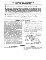
CARE AND MAINTENANCE
WARNING: Turn o heater and let cool before servicing.
CAUTION: You must keep control areas, burner, and circulating air passageways of heater
clean. Inspect these areas of heater before each use. Have heater inspected yearly by a
qualied service person. Heater may need more frequent cleaning due to excessive lint
from carpeting, bedding material, pet hair, etc.
WARNING: Failure to keep the primary air opening(s) of the burner(s) clean may result in sooting
and property damage.
BURNER ORIFICE HOLDER AND PILOT AIR INLET HOLE
The primary air inlet holes allow the proper amount of air to mix with the gas. This provides a clean
burning ame. Keep these holes clear of dust, dirt, lint and pet hair. Clean these air inlet holes prior to
each heating season. Blocked air holes will create soot. We recommend that you clean the unit every
three months during operation and have heater inspected yearly by a qualied
service person.
We also recommend that you keep the burner tube and pilot assembly clean and free of dust and dirt.
To clean these parts we recommend using compressed air no greater than 30 PSI. Your local
computer store, hardware store or home center may carry compressed air in a can. If using
compressed air in a can, please follow the directions on the can. If you don’t follow directions on the
can, you could damage the pilot assembly.
BURNER FLAME PATTERN
Figure 31 shows a correct burner ame pattern. Figure 32 shows an incorrect burner ame pattern.
The incorrect burner ame pattern shows sporadic, irregular ame tipping. The ame should not be
dark or have an orange/reddish tinge.
Note: When using the heater the rst time, the ame will be orange for approximately one hour until
the log cures.
If burner ame pattern is incorrect, as shown in Figure 32
• turn heater o (see To Turn O Gas to Appliance, page 24).
• see Troubleshooting, page 34.
2-6 inches
above logs
6-12 inches
above logs
Fig. 31 - Correct/Normal Flame Pattern
with short ames
Fig. 32 - Incorrect/Abnormal Flame
Pattern with tall ames

33
CARE AND MAINTENANCE
LOG SET
• If you remove the log set for cleaning, refer to page 21, for placement instructions.
• Replace log set if broken or chipped (dime sized or larger).
CABINET
Air Passageways
Use a vacuum cleaner or pressurized air to clean.
Exterior
Use a soft cloth dampened with a mild soap and water mixture. Wipe the cabinet to remove dust.
1. Shut o unit including pilot. Allow unit to cool for at least 30 minutes.
2. Inspect burner, pilot and primary air inlet holes on orice holder for dust and dirt (See Fig. 33).
3. Blow air through the ports/slots and holes in the burner.
4. Check the orice holder located at the end of the burner tube again. Remove any large particles
of dust, dirt, lint or pet hair with a soft cloth or vacuum cleaner nozzle.
5. Blow air into the primary air holes on the orice holder.
6. In case any large clumps of dust have now been pushed into the burner repeat steps 3 and 4.
Clean the pilot assembly also. A yellow tip on the pilot ame indicates dust and dirt in the pilot
assembly. There is a small pilot air inlet hole about 2" from where the pilot ame comes out of the
pilot assembly (see Figure 34 depending on model). With the unit o, lightly blow air through the air
inlet hole. You may blow through a drinking straw if compressed air is not available.
A
Primary Air
Inlet Hole
Burner Tube
Shutter
Fig. 24 - Primary Air Inlet Hole
on Burner Tube
Fig. 33 - Primary Air Inlet
Slot on Burner Tube
Fig. 34 - Pilot Inlet Air Hole
(Propane/LP Gas)
LP PILOT
NG PILOT
DUAL FUEL MODELS
AIR INLET HOLE AIR INLET HOLE

34
TROUBLESHOOTING
WARNING: If you smell gas:
• Shut o gas supply.
• Do not try to light any appliance.
• Do not touch any electrical switch; do not use any phone in your building.
• Immediately call your gas supplier from a neighbor’s phone. Follow the gas supplier’s instructions.
• If you cannot reach your gas supplier, call the re department.
IMPORTANT: Operating heater where impurities in air exist may create odors. Cleaning supplies, paint, paint
remover, cigarette smoke, cements and glues, new carpet or textiles, etc., create fumes. These fumes may mix
with combustion air and create odors.
WARNING: Make sure that power is turned o before proceeding.
WARNING: Turn o and let cool before servicing. Only a qualied service person should service
and repair heater.
CAUTION: Never use a wire, needle, or similar object to clean ODS/pilot. This can damage ODS/ pilot unit.
PROBLEM POSSIBLE CAUSE CORRECTIVE ACTION
When ignitor button
is pressed in, there
is no spark at ODS/
pilot.
There is a sputtering
sound coming from
the Liquid Propane
pilot that is a nuisance.
When operating on
Natural Gas (NG) and
the NG pilot is lit.
1. Use of Natural Gas. 1. Call Customer Service.
1. Ignitor electrode is
positioned wrong.
2. Ignitor electrode is broken.
3. Ignitor electrode is not
connected to ignitor cable.
4. Ignitor cable is pinched or
wet.
5. Damaged ignitor cable.
6. Bad push button ignitor.
7. Bad Battery.
1. Replace electrode.
2. Replace electrode.
3. Replace ignitor cable
4. Free ignitor cable if pinched by any
metal or tubing. Keep ignitor cable dry.
5. Replace ignitor cable.
6. Replace push button ignitor.
7. Check Battery and replace if needed.
When ignitor button
is pressed in, there
is a spark at ODS/
pilot but no ignition.
1. Gas supply is turned o or
equipment shuto valve is
closed.
2. Control knob not fully
pressed in while pressing
ignitor button.
3. Air in gas lines when
installed.
4. ODS / pilot is clogged.
5. Gas regulator setting is not
correct.
6. Control knob not in PILOT
position.
7. Depleted gas supply (propane).
1. Turn on gas supply or open equipment
shuto valve.
2. Fully press in control knob while
pressing ignitor button.
3. Continue holding down control knob.
Repeat igniting operation until air is
removed.
4. Clean ODS/pilot (see Care and
Maintenance, page 25 & 26) or replace
ODS/pilot assembly.
5. Replace gas regulator.
6. Turn control knob to PILOT position.
7. Contact local propane/LP gas company.
SERVICE HINTS
When Gas Pressure Is Too Low
• pilot will not stay lit
• burners will have delayed ignition
• heater will not produce specied heat
• for propane/LP units, propane/LP gas supply may be low
You may feel your gas pressure is too low. If so, contact your local natural or propane/LP gas supplier.

35
TROUBLESHOOTING
PROBLEM POSSIBLE CAUSE CORRECTIVE ACTION
ODS/pilot lights
but ame goes out
when control knob is
released.
1. Control knob is not fully
pressed in.
2. Control knob is not pressed
in long enough.
3. Equipment shuto valve is
not fully open.
4. Thermocouple connection is
loose.
5. Thermocouple damaged.
6. Control valve damaged.
7. Wrong gas setting.
1. Press in control knob fully.
2. After ODS/pilot lights, keep control
knob pressed in 30 seconds.
3. Fully open equipment shuto valve.
4. Hand tighten until snug, and then
tighten ¼ turn more.
5. Replace thermocouple.
6. Contact customer service.
7. Correct gas selection.
Burner(s) does not
light afterODS/pilot
is lit.
1. Burner orice is clogged.
2. Burner orice diameter is
too small.
3. Inlet gas pressure is too low.
1. Clean burner orice (see Care and
Maintenance, page 25 & 26) or contact
customer service.
2. Contact customer service.
3. Contact your gas supplier.
Delayed ignition of
burner(s).
1. Manifold pressure is too low.
2. Burner orice is clogged.
1. Contact your gas supplier.
2. Clean burner (see Care and Mainte-
nance, page 25 & 26) or contact cus-
tomer service.
Burner backring
during combustion.
1. Burner orice is clogged or
damaged.
2. Burner is damaged.
3. Gas regulator is damaged.
1. Clean burner orice (see Care and
Maintenance, page 25 & 26 or contact
customer service.
2. Contact dealer or customer service.
3. Replace gas regulator.
High yellow ame
during burner
combustion
1. Not enough air.
2. Gas regulator is defective.
3. Inlet gas pressure is too low.
1. Check burner for dirt and debris. If found,
clean burner (see Care and Maintenance,
page 25 & 26).
2. Replace gas regulator.
3. Contact your gas supplier.
Gas odor during
combustion.
1. Foreign matter between
control valve and burner.
2. Gas leak. (See Warning
Statement at top of page 27).
1. Take apart gas tubing and remove foreign
matter.
2. Locate and correct all leaks (see “Check-
ing Gas Connections,” page 19).
Heater produces a
clicking/ticking noise
just after burner is lit
or shut o.
1. Metal is expanding while
heating or contracting
while cooling.
1. This is common with most heaters. If
noise is excessive, contact qualied
service technician.
Burner(s) does not
light afterODS/pilot
is lit. (Heater is set
up for NG.)
1. Inlet gas pressure is too
high.
1. Contact your gas supplier.

36
TROUBLESHOOTING
PROBLEM POSSIBLE CAUSE CORRECTIVE ACTION
White powder resi-
due forming within
burner box or on
adjacent walls or
furniture.
1. When heated, the vapors
from furniture polish, wax,
carpet cleaners, etc., turn into
white powder residue.
1. Turn heater o when using furniture
polish, wax, carpet cleaner or similar
products.
Heater produces
unwanted odors.
1. Heater is burning vapors
from paint, hair spray, glues,
etc. See IMPORTANT state-
ment, page 27.
2. Gas leak. See Warning
Statement, page 27.
3. Low fuel supply.
1. Ventilate room. Stop using odor
causing products while heater is running.
2. Locate and correct all leaks (see
“Checking Gas Connections,” page 19).
3. Rell supply tank (Propane /LP models).
Heater shuts o in
use (ODS operates).
1. Not enough fresh air is
available.
2. Low line pressure.
3. ODS/pilot is partially
clogged.
1. Open window and/or door for
ventilation.
2. Contact local gas supplier.
3. Clean ODS/pilot (see Care and
Maintenance, page 25 & 26).
Gas odor exists
even when control
knob is in OFF posi-
tion.
1. Gas leak. See Warning
Statement at top of page 27.
2. Control valve is
defective.
1. Locate and correct all leaks (see
“Checking Gas Connections”, page 19).
2. Contact customer service.
Moisture/conden-
sation noticed on
windows.
1. Not enough combustion/
ventilation air.
1. Refer to “Air for Combustion and
Ventilation” requirements, page 9.
Slight smoke or odor
during initial opera-
tion
1. Residues from
manufacturing process.
1. Problem will stop after a few hours of
operation.
Heater produces a
whistling noise when
burner is lit.
. Turning control knob to high (5)
position when burner is cold.
2. Air in gas line.
3. Air passageways on
heater are blocked.
4. Dirty or partially clogged
burner orice.
1. Turn control knob to low (1) position and
let warm up for a minute.
2. Operate burner until air is removed from
line. Have gas line checked by local
propane/LP gas company.
3. Observe minimum installation
clearances (Fig. 5,6,7,8 page 13-14).
4. Clean burner (see Care and Maintenance,
page 25 & 26) or contact customer service.

37
REPLACEMENT PARTS LIST
For replacement parts, call our Technical Service Department at 1-877-447-4768, 8:30 a.m. – 4:30 p.m.,
CST, Monday – Friday.
ACCESSORIES
NOTICE: All accessories may not be available for all models.
Glowing Ember Fibers - GEF100 For all models. Material to simulate glowing embers when the
unit is in operation. Creates a realistic glowing eect just like a real re.
1-1
1-2
1-3
1-4
1-6
1-5
1-7
1-8
4
5
6
7-2
7-1
8
12
11
10
2
3
9
4ITEM
NO.
DESCRIPTION QTY
PART NO.
VFL2-VO24DR
VFL2-RO24DR
VFL2-VO30DR
VFL2-R030DR
VFL2-MO24DR VFL2-MO30DR
1 Log Set (complete) 1 80-06-045 80-06-046
See
installation
insert
See
installation
insert
1-1 Log 1 1 4UB2A 4UB3A
1-2 Log 2 1 H-010A H-003A
1-3 Log 3 1 H-010B H-003B
1-4 Log 4 1 H-0075 H-0075
1-5 Log 5 1 H-0139 H-0139
1-6 Log 6 1 H-0812 H-0812
1-7 Log 7 1 H-0370 H-0370
1-8 Log 8 1 H-0356 H-0356
2 Grate 1 GP289-01 GP290-01 GP289-01 GP290-01
3 Grate End Cap 1 GP287-02 GP287-02 GP287-02 GP287-02
4 ODS Pilot - NG 1 GZ20-30B GZ20-30B GZ20-30B GZ20-30B
5 ODS Pilot - LP 1 GZ20-29B GZ20-29B GZ20-29B GZ20-29B
6 Selector Knob 1 GZ20-17 GZ20-17 GZ20-17 GZ20-17
7-1 Regulator, (NG) Natural Gas 5" WC 1 GR-130B8-GHP GR-130B8-GHP GR-130B8-GHP GR-130B8-GHP
7-2 Regulator, (LP) Propane 10" WC 1 GR-130A8-GHP GR-130A8-GHP GR-130A8-GHP GR-130A8-GHP
8 Ignitor Module 1 GZ20-32a GZ20-32a GZ20-32a GZ20-32a
9 Ember Bed 1 GZ36-18 GZ36-18 GZ36-18 GZ36-18
10 Control Valve 1 GZ20-26 GZ20-26 GZ20-26 GZ20-26
11 Remote Receiver 1 80-05-102 80-05-102 80-05-102 80-05-102
12 Thermostat Remote 1 80-05-101 80-05-101 80-05-101 80-05-101
*Item/version not shown in exploded parts diagram
/