Page is loading ...

Original Instruction Manual
BS350S Premium
14" Bandsaw
Always wear safety glasses when
using woodworking equipment.
Always read the instructions
provided before using
woodworking equipment.
i
Kg
Version 3.0
January 2013
To register this product please visit
www.recordpower.info
It is important to register your product as soon as possible in order to receive efficient after sales
support and be entitled to the full 5 year guarantee. Your statutory rights are not affected.
Please see back cover for contact details.
Important
For your safety read instructions carefully
before assembling or using this product.
Save this manual for future reference.
i
Kg

2
Terms & Conditions Of Usage
Explanation of Symbols 3
General Health & Safety Guidance 4
Additional Health & Safety for Bandsaws 6
Record Power Guarantee 7
EU Declaration Of Conformity 36
User Manual
1. Getting To Know Your Bandsaw 8
2. Machine Specification 8
3. Stand & Wheel Kit Assembly 9
4. Machine Assembly 13
5. Setting Table Square to the Saw Blade 17
6. Bandsaw Blade Set Up 18
7. Drive Belt Adjustment & Speed Change 20
8. Electrical Connection & Wiring Diagram 21
9. Operation & Bandsawing Practice 22
10. Dust Extraction 26
11. Maintenance 27
12. Trouble Shooting 30
13. Parts Diagrams 31
14. Parts List 35
15. Assembly of the Optional BS350S-W Pedal Wheel Kit 37
EU Declaration of Conformity 39
Part Description Part Number
Blades
BB103121406 1/4” x 6 TPI Skip tooth pattern
BB103123806 3/8” x 6 TPI Skip tooth pattern
BB103121204 1/2” x 4 TPI Skip tooth pattern
BB103121206 1/2” x 6 TPI Skip tooth pattern
BB103123403 3/4” x 3 TPI Skip tooth pattern
BB10312-3PACK 1/4”, 3/8” & 5/8" Skip tooth pattern
SBS300-127 Table Insert
Bandwheels
SRPBS12-101 Drive belt
SBS350-26 Bandwheel tyre
SBS350-18 Wheel bearing
SBS300-58 Brush
Upper Blade Guides
SBS3505-149 Hex bolt M6-1.0 x 15
Description Part Number
SBS300-153 Upper guide support block
SBS300-146 Blade support shaft
Lower Blade Guides
SBS3505-113 Washer
SBS300-130 Left cover
SBS3505-131 Hex socket screw
SBS300-132 Lower blade guide support
SBS300-135 Right cover
SBS3505-136 Hex bolt M5-0.8 x 10
SBS3505-137 Flat washer M5
Contents
Consumable Spare Parts Quick Find

3
The symbols and their meanings shown below may be used throughout this manual.
Please ensure that you take the appropriate action wherever the warnings are used.
Explanation of Symbols
Mandatory
Instructions
i
Kg
i
Kg
i
Kg
i
Kg
i
Kg
i
Kg
i
Kg
i
Kg
Warnings
Read and fully understand the instruction
manual before attempting to use
the machine.
Indicates an instruction that requires
particular attention
Wear protective eyewear
Use respiratory protective equipment
Use suitable protective footwear
Use hearing protection
Use protective work gloves
Indicates a risk of severe personal injury
or damage to the machine
Indicates a risk of severe personal injury
from electrical shock
Risk of personal injury from lifting of
heavy items
Indicates a risk of severe personal injury
from airborne objects
Risk of fire
i
Kg
i
Kg
i
Kg
i
Kg

4
General Health & Safety Guidance
Ensure that you carefully read and fully understand the
instructions in this manual before assembly, installation and
use of this product. Keep these instructions in a safe place for
future reference.
WARNING: for your own safety, do not attempt to operate this machine
until it is completely assembled and installed according to
these instructions.
WARNING: When using any machine, basic safety precautions should
always be followed to reduce the risk of fire, electric shock and
personal injury.
Safe Operation
1. Use Personal Protective Equipment (PPE)
• The operation of any machine can result in foreign objects being thrown
into your eyes, which can result in severe eye damage. Protective
eyewear or other suitable eye protection or face shield should be used at
all times. Everyday spectacles only have impact resistant lenses. They are
not protective eyewear and do not give additional lateral protection.
• Use respiratory protective equipment (dust mask etc.) if the machining
operation creates dust. Exposure to high levels of dust created by
machining hardwoods, softwoods and man made composite boards can
result in serious health problems. Some imported hardwoods give off
highly irritating dust, which can cause a burning sensation. The use of
respiratory protective equipment should not be seen as an alternative to
controlling the risk of exposure at source by using adequate dust
extraction equipment.
• The use of ear plugs or ear defenders is recommended when the machine
is in use, particularly if the noise level exceeds 85 dB.
• Wear suitable protective gloves when handling cutting tools or blades.
Gloves should NOT be worn when using the machine as they can be
caught in moving parts of the machine.
• Non-slip safety footwear is recommended when using the machine and
handling large work pieces.
2. Dress appropriately
• Do not wear loose clothing, neckties or jewellery; they can be caught in
moving parts of the machine.
• Roll up long sleeves above the elbow.
• Wear protective hair covering to contain long hair.
3. Safety warnings
• Find and read any warning labels on the machine.
• It is important that any labels bearing health and safety warnings are
not removed, defaced or covered. Replacement labels can be obtained by
contacting our Customer Service Department.
4. Familiarise yourself with the machine
• If you are not thoroughly familiar with the operation of this machine,
obtain advice from your supervisor, instructor, or other qualified person or
contact your retailer for information on training courses. Do not use this
machine until adequate training has been undertaken.
5. Take care when moving or positioning the machine
• Some machines can be very heavy. Ensure the floor of the area in which
the machine is to be used is capable of supporting the machine.
• The machine and its various components can be heavy.
Always adopt a safe lifting technique and seek assistance when lifting
heavy components. In some cases it may be necessary to use mechanical
handling equipment to position the machine within the work area.
• Some machines have optional wheel kits available to allow them to be
manoeuvred around the workshop as required. Care should be taken to
install these according to the instructions provided.
• Due to the nature of the design of some machines the centre of gravity
will be high making them unstable when moved. Extreme care should be
taken when moving any machine.
• If transportation of the machine is required then all precautions relating
to the installation and handling of the machine apply. In addition, ensure
that any vehicles or manual handling equipment used for transportation
are of adequate specification.
6. The machine should be level and stable at all times
• When using a leg stand or cabinet base that is designed to be fitted to
the machine, always ensure that it is securely fastened to the machine
using the fixings provided.
• If the machine is suitable to be used on a workbench, ensure that the
workbench is well constructed and capable of withstanding the weight
of the machine. The machine should always be securely fastened to the
workbench with appropriate fixings.
• Where possible, floor standing machines should always be secured to the
floor with fixings appropriate to the structure of the floor.
• The floor surface should be sound and level. All of the feet of the
machine should make contact with the floor surface. If they do not, either
re-locate the machine to a more suitable position or use packing shims
between the feet and the floor surface to ensure the machine is stable.
7. Remove adjusting keys and wrenches
• Ensure that all adjusting wrenches and keys are removed before
switching the machine ‘ON’. There is a risk of severe personal injury or
damage to the machine from airborne objects.
8. Before switching the machine ‘ON’
• Clear the machine table of all objects (tools, scrap pieces etc.)
• Make sure there is no debris between the work piece and the
table / work support.
• Ensure that the work piece is not pressed against, or touching the saw
blade or cutting tool.
• Check all clamps, work holding devices and fences to ensure that they
are secure and cannot move during machining operations.
• Plan the way that you will hold and feed the work piece for the entire
machining operation.
9. Whilst machining
• Before starting work, watch the machine while it runs. If it makes
an unfamiliar noise or vibrates excessively, switch the machine ‘OFF’
immediately and disconnect it from the power supply. Do not restart until
finding and correcting the source of the problem.
10. Keep the work area clear
• Working clearances can be thought of as the distances between
machines and obstacles that allow safe operation of every machine
without limitation. Consider existing and anticipated machine needs,
size of material to be processed through each machine and space for
auxiliary stands and/or work tables. Also consider the relative position of
each machine to one another for efficient material handling. Be sure to
allow yourself sufficient room to safely operate your machines in any
foreseeable operation.
• Cluttered work areas and benches create the risk of accidents. Keep
benches clear and tidy away tools that are not in use.
• Ensure that the floor area is kept clean and clear of any dust and debris
that may create trip or slip hazards.
11. Consider the work area environment
• Do not expose the machine to rain or damp conditions.
• Keep the work area well lit and ensure that there is artificial lighting
available when there is insufficient natural light to effectively light the
work area. Lighting should be bright enough to eliminate shadow and
prevent eye strain.
• Do not use the machine in explosive environments eg. in the presence of
flammable liquids, gases or dust.
• The presence of high levels of dust created by machining wood can
present a risk of fire or explosion. Always use dust extraction equipment
to minimise the risk.
12. Keep other persons away (and pets)
• The machine is designed to be used by one person only.
• Do not let persons, especially children, touch the machine or extension
cable (if used) and keep visitors away from the work area.
• Never leave the machine running unattended. Turn the power supply off
and do not leave the machine unattended until it comes to a

5
complete stop.
• If the work area is to be left unattended, all machinery should be
switched ‘OFF’ and isolated from the mains power supply.
13. Store machines safely when not in use
• When not in use, machines should be stored in a dry place, out of reach
of children. Do not allow persons unfamiliar with these instructions or
with the machine to operate it.
14. Do not overreach
• Choose a working position that allows your body to remain balanced
and feed the work piece in to the machine without overreaching.
• Keep proper footing and balance at all times.
15. Electrical supply
• Electrical circuits should be dedicated to each machine or large enough
to handle combined motor amp loads. Power outlets should be located
near each machine so that power or extension cables are not obstructing
high-traffic areas. Observe local electrical guidelines for proper
installation of new lighting, power outlets, or circuits.
• The machine must be connected to an earthed power supply.
• The power supply must be equipped with a circuit breaker that provides
short circuit, overload and earth leakage protection.
• The voltage of the machine must correspond to the voltage of the mains
power supply.
• The mains plug fitted to the machine should always match the power
outlet. Do not modify the plug in any way. If a replacement plug is
required it should be fitted by a competent person and of the correct
type and rating for the machine.
• If you are unsure about any electrical connections always consult a
qualified electrician.
16. Avoid unintentional starting of the machine
• Most machines are fitted with a no-volt release (NVR) switch to prevent
unintentional starting. If in doubt always ensure the machine switch
is in the ‘OFF’ position before connecting it to the power supply. This
means the machine will not automatically start up after a power cut or
switching on of the power supply, unless you first reset the start switch.
17. Outdoor use
• Your machine should not be used outdoors.
18. Extension cables
• Whenever possible, the use of extension cables is not recommended.
If the use of an extension cable is unavoidable, then it should have
a minimum core cross section of 2.5 mm² and limited to a maximum
length of 3 metres.
• Extension cables should be routed away from the direct working area to
prevent a trip hazard.
19. Guard against electric shock
• Avoid body contact with earthed or grounded surfaces such as pipes
and radiators. There is an increased risk of electric shock if your body is
earthed or grounded.
20. Always work within the machine’s intended capacities
• Operator safety and machine performance are seriously adversely
affected if attempts to make the machine perform beyond its limits
are made.
21. Do not abuse the power cable
• Never pull the power cable to disconnect it from the power socket.
Always use the plug.
• Keep the power cable away from heat, oil and sharp edges.
• Do not use the power cable for carrying or moving the machine.
22. Secure the work piece
• Ensure that the work piece is securely held before starting to machine it.
• When working within 300 mm of the machining area, always use a push
stick to feed the work piece in to the blade or cutting tool. The push stick
should have a minimum length of 400 mm. If the push stick becomes
damaged, replace it immediately.
• Use extra supports (roller support stands etc.) for any work pieces large
enough to tip when not held down to the table top.
• Do not use another person as a substitute for a table extension, or as
additional support for a work piece that is longer or wider than the basic
table, or to help feed, support, or pull the work piece.
• Do not attempt to machine more than one work piece at a time.
• When feeding the work piece towards the blade or cutting tool never
position your hands in direct line of the cutting path. Avoid awkward
operations and hand positions where a sudden slip could cause your
hand or fingers to move into the machining area.
23. Stay alert
• Safety is a combination of operator common sense and alertness at all
times when the machine is being used.
• Use all machines with extreme care and do not use the machine when
you are tired or under the influence of drugs, alcohol or medication.
24. Use the correct tool for the job
• Do not use the machine for any purpose other than which it
was designed.
• When selecting replacement cutting tools and blades, always ensure that
they are designed to cut the material that you intend to use them for. If
in any doubt seek further advice from the manufacturer.
25. Connect dust extraction equipment
• Always use dust extraction equipment. The dust extractor should be of
suitable size and capacity for the machine that it is connected to and
have a filtration level appropriate to the type of waste being collected.
Refer to the relevant section of the manual for details of the specific dust
extraction requirements for this machine.
• The dust extractor should be switched ‘ON’ before starting the machine
that it is connected to. The dust extractor should be left running for 30
seconds after the last machining operation is complete in order to clear
any residual waste from the machine.
26. Ensure that the machine is correctly guarded
• Never use the machine if any of the standard safety guards and
equipment are removed or damaged.
• Some machines incorporate safety interlocks to prevent the machine
from being used without the guards in place. Never attempt to bypass
or modify the interlocks to allow the machine to be used without the
guards in place.
27. Maintain your machine with care
• This manual gives clear instructions on installation, set up and
operation of the machine and also details any routine and preventative
maintenance that should be performed periodically by the user.
• Remember always to switch off and unplug the machine from the power
supply before carrying out any setting up or maintenance operations.
• Follow any instructions for the maintenance of accessories
and consumables.
• Do not use compressed air to clean the machine. Always use a brush to
dislodge dust in places that are awkward to reach and a dust extractor
to collect the waste.
• Inspect electric cables periodically and, if damaged, have them replaced
by an authorised service facility or qualified electrician.
• Inspect extension cables (if used) periodically and replace if damaged.
28. Keep cutting tools sharp and clean
• Correctly maintained cutting tools are easier to control and less likely
to bind.
• Cutting tools and blades can become hot during use. Take extreme care
when handling them and always allow them to cool before changing,
adjusting or sharpening them.
29. Disconnect the machine from the power supply
• When not in use, before servicing, changing blades etc. always
disconnect the machine from the power supply.
30. Check for damaged parts
General Health & Safety Guidance - cont.

6
• Before each use of the machine, it should be carefully checked to
determine that it will operate properly and perform its
intended function.
• Check for alignment of moving parts, binding of moving parts, breakage
of parts and any other conditions that may affect the operation of
the machine.
• A guard or other part that is damaged should be properly repaired
or replaced by a qualified person unless otherwise indicated in this
instruction manual.
• Do not use the machine if the switch does not turn the machine ‘ON’
and ‘OFF’.
• Have defective switches replaced by a qualified person.
31. Warning!
• The use of any accessory or attachment, other than those recommended
in this instruction manual, or recommended by our Company may present
a risk of personal injury or damage to the machine and invalidation of
the warranty.
32. Have your machine repaired by a qualified person
• This machine complies with the relevant safety rules and standards
appropriate to its type when used in accordance with these instructions
and with all of the standard safety guards and equipment in place. Only
qualified persons using original spare parts should carry out repairs.
Failure to do this may result in considerable danger to the user and
invalidation of warranty.
33. Caution! Motor may become hot during use
• It is normal for motors on some machines to become hot to the touch
during use. Avoid touching the motor directly when in use.
General Health & Safety Guidance - cont.
Safe Operation
1. Familiarise yourself with the machine
• Machining operations using bandsaws have a history of serious accidents.
Most result from contact with the moving blade while presenting material
to the blade or moving it from the table. Other minor accidents can occur
whilst setting, cleaning, adjusting or maintaining the machine.
• The machine is designed for cutting wood and composite board (plywood,
MDF etc.). Certain plastics can also be cut using a suitable blade.
2. Before switching the machine ‘ON’
• Ensure that the blade is correctly tensioned and aligned on the
bandwheels and the blade guides are correctly adjusted.
• Ensure that the teeth of the blade are pointing downwards.
• Check the condition of the blade to ensure that no teeth are missing,
damaged or deformed and the blade is not cracked or split. If any of
these conditions apply, replace the blade immediately.
• Ensure that the saw blade type and width are suitable for the material to
be cut.
• Check that the blade width is within the minimum and maximum
permitted on the machine and that the thickness of the blade is suitable
for the diameter of the wheel.
• Some machines have more than one cutting speed. For most wood
cutting applications the faster of the speeds should be used.
• Check the condition of the table insert. Replace it immediately if it is
damaged or showing signs of wear.
• Adjust the guard as close as possible to the work piece being cut.
• Check that access doors are fully closed and that the latches are secure.
3. Whilst machining
• Never apply sideways pressure to the blade as this may cause the blade
to break.
• Care must be taken when cutting wood with knots, nails or cracks in
it and / or dirt on it, as these can cause the blade to get stuck. If this
happens, switch the machine ‘OFF’ immediately and follow the procedure
detailed in the manual to remove the blade from the work piece.
• If cutting cylindrical timber use a suitable jig to prevent twisting of the
work piece.
4. This machine falls under the scope of the ‘Health & Safety at Work etc.
Act 1974’, and the ‘Provision & Use of Work Equipment Regulations 1998’.
In addition the elimination or control of risks from wood dust is included in
the above regulations and the ‘Control of Substances Hazardous to Health
(COSHH) Regulations 2002’. We recommend that you study and follow
these regulations.
Further guidance can be found in the ‘Safety in the use of narrow bandsaws
– Woodworking sheet No.31’ and the ‘Safe use of woodworking machinery’
code of practice booklet (L114) published by Health & Safety Executive and
available from their website www.hse.gov.uk.
Additional Health & Safety for Bandsaws

7
Record Power Guarantee
“Products” means the Products sold by Record Power subject to these
terms and conditions;
“Record Power” is Record Power Limited, whose company registration
number is 4804158 and registered office address is Centenary House, 11
Midland Way, Barlborough Links, Chesterfield, Derbyshire S43 4XA and sells
through a network of Authorised Dealers;
“Authorised Distributor” is the nominated importer for your region
who will generally sell through a network of Authorised Dealers. Details of
Authorised Distributors for specific countries can be found in the Product
manual or at www.recordpower.info;
“Authorised Dealer” is a retailer or business authorised to sell Record
Power Products to end users.
1 Guarantee
1.1 Record Power guarantees that for a period of 5 years from the date
of purchase the components of qualifying Products (see clauses 1.2.1
to 1.2.9) will be free from defects caused by faulty construction
or manufacture.
1.2 During this period Record Power, its Authorised Distributor or
Authorised Dealer will repair or replace free of charge any parts
which are proved to be faulty in accordance with paragraphs 1.1
above provided that:
1.2.1 you follow the claims procedure set out in clause 2 below;
1.2.2 Record Power, our Authorised Distributor or Authorised Dealer are
given a reasonable opportunity after receiving notice of the claim to
examine the Product;
1.2.3 if asked to do so by Record Power, its Authorised Distributor or
Authorised Dealer, you return the Product, at your own cost, to
Record Power's premises or other approved premises such as those
of the Authorised Distributor or supplying Authorised Dealer, for the
examination to take place;
1.2.4 the fault in question is not caused by industrial use, accidental
damage, fair wear and tear, wilful damage, neglect, incorrect
electrical connection, abnormal working conditions, failure to follow
our instructions, misuse, or alteration or repair of the Product without
our approval;
1.2.5 the Product has been used in a domestic environment only;
1.2.6 the fault does not relate to consumable Products such as blades,
bearings, drive belts or other wearing parts which can reasonably
be expected to wear at different rates depending on usage (for full
details contact Record Power or your local Authorised Distributor);
1.2.7 the Product has not been used for hire purposes, by you or by a
previous owner;
1.2.8 the Product has been purchased by you as the guarantee is not
transferable from a private sale.
1.2.9 where the Product has been purchased from a retailer, the 5 year
guarantee is transferable and begins on the date of the first purchase
of the Product and in the event of a claim under this guarantee
proof of the original purchase date will be required to validate the
warranty period.
2 Claims Procedure
2.1 In the first instance please contact the Authorised Dealer who
supplied the Product to you. In our experience many initial problems
with machines that are thought to be due to faulty parts are actually
solved by correct setting up or adjustment of the machines. A good
Authorised Dealer should be able to resolve the majority of these
issues much more quickly than processing a claim under
the guarantee.
2.2 Any damage to the Product resulting in a potential claim under the
guarantee must be reported to the Authorised Dealer from which it
was purchased within 48 hours of receipt.
2.3 If the Authorised Dealer who supplied the Product to you has been
unable to satisfy your query, any claim made under this Guarantee
should be made directly to Record Power or its Authorised Distributor
(for details of the Authorised Distributor in your country please see
your Product manual or check www.recordpower.info for details).
The claim itself should be made in a letter setting out the date and
place of purchase, and giving a brief explanation of the problem
which has led to the claim. This letter should then be sent with
proof of the purchase date (preferably a receipt) to Record Power or
its Authorised Distributor. If you include a phone number or email
address this will help to speed up your claim.
2.4 Please note that it is essential that the letter of claim reaches Record
Power or its Authorised Distributor on the last day of this Guarantee
at the latest. Late claims will not be considered.
3 Limitation of Liability
3.1 We only supply Products for domestic and private use. You agree not
to use the Product for any commercial, business or re-sale purposes
and we have no liability to you for any loss of profit, loss of business,
business interruption or loss of business opportunity.
3.2 This Guarantee does not confer any rights other than those expressly
set out above and does not cover any claims for consequential loss
or damage. This Guarantee is offered as an extra benefit and does
not affect your statutory rights as a consumer.
4 Notice
This Guarantee applies to all Products purchased from an Authorised
Dealer of Record Power within the United Kingdom of Great
Britain and Northern Ireland. Terms of Guarantee may vary in other
countries – please check with the Authorised Distributor in your
country (details of the Authorised Distributor for your country can be
found in the manual or at www.recordpower.info).

8
2. Machine Specification
1. Getting To Know Your Bandsaw
Fig.1
A Blade Tensioning Knob
B Rise & Fall Hand Wheel
C Blade
D Upper Blade Guides
E Table
F Rip Fence
G Rip Fence Rail
H Belt Tension & Speed Change Handle
I Wheel Kit
J Blade Tension Release Cam Handle
K Rise & Fall Lock Knob
L Blade Tracking Knob
M Table Tilting Knob
N Motor Rating Plate
O 100 mm Dust Extraction Port
P Motor
Q On/Off Switch and Emergency Stop
Blade length: 2630 mm (103
1
/2”)
Blade width: 6 - 19 mm (
1
/
4
” -
3
/
4
”)
Max depth of cut: 230 mm
Throat depth: 340 mm
Table size: 545 x 400 mm
Max width blade to rip fence: 280 mm
Table height: 998 mm
Extraction port: 100 mm
Motor: 230 V / 50 Hz / 1
1
/2 hp / 1120 W
Full load current: 6.7 A
Weight: 100 kg
Footprint: 610 x 440 mm
Dimensions: Height 1760 mm x width 770 mm x depth 690 mm
Sound power level: 82 dB (no load), 100 dB (load)
Sound pressure level: 75 dB (no load), 90 dB (load)
A
B
C
F
Q
I
D
E
H
G
K
O
J
L
P
M
N

9
3. Stand & Wheel Kit Assembly
3.1 Stand & Wheel Kit Assembly
CAUTION! The machine is heavy. Additional help or a suitable
lifting device or support will be required for lifting the machine
onto the stand.
The stand and wheel kit comes as a self assembly unit, Fig.3.1.
Stand
1. 2 x Long mid brace supports
2. Medium mid brace support
3. Short mid brace support
4. 2 x Long top brace supports
5. 2 x Short top brace supports
6. 4 x Legs
7. 24 x Stand fixing nuts bolts and washers (each)
8. 4 x Long fixing bolts, nuts and washers
Wheel Kit
9. 8 x Hex bolts
10. 2 x D-Handle brackets
11. 8 x Nylon nuts
12. 8 x Washers
13. D-handle
14. 2 x Fixed wheels
1
3
2
4
5
6
7
Fig.3.1
( x 24 )
i
Kg
i
Kg
9
10
11
12
13 14
8

10
Fig.3.3
Fig.3.4
Fig.3.5
Fig.3.6Fig.3.2
Fig.3.7
LONG TOP BRACE
SUPPORT
SHORT TOP BRACE
SUPPORTS
LONG MID BRACE
SUPPORT
i
Kg
3. Stand & Wheel Kit Assembly - cont.
SHORT MID
BRACE SUPPORT
Note: When assembling this legstand do
not fully tighten the nuts and bolts until
the assembly is complete.
When fitting the optional pedal wheekit
during initial assembly of the bandsaw,
please do so before attaching the
bandsaw to the leg stand to ensure
greater safety and ease of fitment.
When fitting the optional pedal wheelkit,
the short mid brace support (Fig. 3.7) at
the front of the bandsaw should
be removed.
Please see section 15 for assembly
instructions of the BS350S-W Pedal
Wheel Kit.
3.2 Stand Assembly
1. Locate the first leg and secure it to one of the
long top brace supports using the nuts, bolts and
washers supplied Fig.3.2.
2. In the same way, attach the second leg to the
brace support Fig.3.3.
3. Locate the short top brace supports and fix
them to the legs as shown Fig.3.4.
4. Continue in this way until all of the legs and
top brace supports have been fitted Fig.3.5.
5. The locating holes a third of the way down
each leg are for securing the mid brace supports.
Fix the long mid brace supports to the frame
using the nuts, bolts and washers Fig.3.6.
6. Finally, fit the short and medium mid brace
supports to the shorter sides Fig.3.7. The short
mid brace support is fitted to holes positioned
two thirds of the way up each leg. The medium
mid brace support is positioned in the lower
holes in each leg.

11
3. Stand & Wheel Kit Assembly - cont.
3.3 Wheel Kit Assembly
1. Attach the fixed wheels to the rear legs of
the machine stand using the M6 x 16 hex bolts,
Washers, and M6 nuts provided. Fig 3.8.
The rear of the stand is the side which features
the medium mid brace support.
2. Assemble the D-handle to the front short top
brace of the stand, using the D-handle brackets,
M6 x 16 Hex bolts, Washers and M6 Nuts
provided. Fig 3.9.
3. Fully tighten all of the fixings to secure the
wheels and handle assembly (take care not to
over tighten the fixings as damage to the threads
may occur).
PLEASE NOTE: For your safety only use
the handle to pull the machine. It is
unsafe to push the machine using the
handle.
When lifting the stand ensure the front
legs are not raised higher than 200 mm
from the ground (or at an angle of more
than 17º).
Fig.3.8
Fig.3.9
HANDLE
BOLTS & NUTS
i
Kg

12
3. Stand & Wheel Kit Assembly - cont.
3.4 Fitting the bandsaw to the stand
CAUTION! The machine is heavy.
Additional help or a suitable lifting
device or support will be required for
lifting the machine onto the stand.
1. Lift the bandsaw over the stand. and place
the long fixing bolts through the four location
holes in the bandsaw base Fig.3.11.
2. Secure the bandsaw to the stand with the
remaining washers and nuts Fig.3.12.
Fig.3.10
Fig.3.12
Fig.3.11
LONG FIXING BOLTS
1. Feed the long fixing bolts up through the
stand and secure the four corners using the
washers and bolts provided Fig.3.10. Once
this is achieved the whole stand can be fully
tightened ready for the bandsaw to be fitted.
LOCATION
HOLES
200mm 17º
WARNING! For your safety only use the
handle to pull the machine. It is unsafe
to push the machine using the handle.
When lifting the stand ensure the front
legs are not raised higher than 200 mm
from the ground (or at an angle of more
than 17º). Fig.3.13.
Ensure the bandsaw is fitted to the stand
so that the wheels are at the rear (spine
end) of the machine.
Fig.3.13
i
Kg
i
Kg
i
Kg
i
Kg

13
4. Machine Assembly
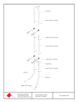
4.1 Unpacking and components included
The machine is supplied partly assembled. Prior to use, further assembly is
required.
When unpacking the machine, in addition to the bandsaw itself, the
following components are included for the initial assembly Fig.4.1:
1. 2 x Nuts and small crank handle
2. Rise & fall hand wheel and crank handle
3. Blade tensioning knob
Table Assembly
4. Table stop safety bolt
5. Table
6. 4 x Table fixing bolts, washers and spring washers
7. 4 x Long fixing bolts, nuts and washers
8. Table levelling nut and bolt
9. Scale Bracket
10. 2 x hex head bolts
11. Push stick, holder and nut.
Fence Assembly
12. Fence bar
13. Fence fixing bar nuts and washers
14. Fence carrier
15. Fence
16. Fence lock knob
17. 2 x Nuts, bolts and washers
1
4
2
5
9
6
11
12
17
1514
16
13
3
Fig.4.1
7 8
( x 4 )
10

14
4. Machine Assembly - cont.
Fig.4.4
TRUNNION
Fig.4.5
TRUNNION
TABLE FIXING BOLT & WASHER
4.2 Rise & fall hand wheel
Attach the rise and fall hand wheel to the rise and fall shaft and tighten
the socket head bolt with a 6 mm hex wrench, then attach the handle and
tighten with a 10 mm spanner (See Fig.4.2).
4.3 Belt tension handle
Attach small crank handle to belt tension and speed mechanism with
10 mm spanner (not supplied) (See Fig.4.3).
4.4 Fitting the table
Tools Required: - 13 mm spanner (not supplied)
With the help of another person, lift the working table onto the trunnion.
Mount the working table on the trunnion using the supplied 4 x table
fixing bolts and 4 x washers (See Fig.4.4 front view & 4.5 rear view).
4.5 Fitting the tension knob
To fit the tension knob, slot it into the keyway on the top of the bandsaw.
Fig.4.6.
Fig.4.3
BELT TENSION & SPEED CHANGE
Fig.4.2
RISE & FALL
Fig.4.6
TABLE FIXING BOLT & WASHER

15
Fig.4.7
FENCE BAR
4.6 Fitting the fence bar
Attach the fence bar to the table as shown in Fig. 4.7, ensuring the
washers are placed next to the fixing nuts. Use the remaining 2 nuts and
washers to secure the fence bar from the underside of the table, Fig. 4.8.
Do not fully tighten yet as adjustment may be necessary.
4.7 Assembling the mitre fence
1. Unscrew the locking nuts from the mitre fence Fig.4.9.
2. Place the protractor with the flat edge running parallel to the
mitre fence.
3. Position it in such a way that the fence screws slot into the holes on the
protractor Fig.4.10.
4. Replace and re-tighten the locking nuts.
5. Position the slide underneath the protractor so that the threaded bar sits
in the angle slide and the pivot pin inserts into the pivot hole Fig.4.11
and Fig.4.12.
6. Tighten the ratchet handle onto the threaded bar Fig.4.12.
4. Machine Assembly - cont.
Fig.4.9
Mitre Fence
Fence Screws
Locking Nuts
Fig.4.10
Protractor
Fig.4.11
Slide
Angle Slide
Pivot Pin
Threaded Bar
Ratchet Handle
Fig.4.12
Ratchet Handle
Fig.4.8

16
FENCE
FENCE BAR
MOVEMENT
ADJUSTMENT
COLLAR
FENCE BOLTS
4.8 Fitting the fence carrier
Locate fence carrier onto the fence bar Fig.4.13.
4.9 Fitting the rip fence
Slide the rip fence onto the carrier as shown in Fig. 4.14 and tighten
the two securing knobs. The fence can be used in the upright position as
shown, or the other T slot can be used to give a lower position. This is ideal
for when working with small items, to allow the guides to be located closer
to the workpiece.
4.10 Fence alignment 1
Align the fence assembly in or out until parallel with the mitre fence
slot (See Fig.4.15) by turning the adjustment collars and the fence
bolts accordingly. If the fixing nuts have been tightened, these will need
slackening off before this adjustment can be made.
4.11 Fence alignment 2
Check that the fence is 90º to the table using a suitable square. If no
adjustment is needed, fully tighten the fence bar nuts. If adjustment is
required this is achieved by raising or lowering either side of the fence rail
until the fence itself is 90º to the table, (See Fig.4.16). Once set at 90º
fully tighten the fence bar nuts.
PLEASE NOTE: The fence bar can be located to either the left
or right hand side of the table, allowing the fence to be used
either side of the blade.
4. Machine Assembly - cont.
Fig.4.16
FENCE
FENCE BAR
ADJUSTMENT
Fig.4.15
Fig.4.13
FENCE BAR
Fig.4.14
FENCE LOCK KNOBSECURING KNOBS
FENCE CARRIER

17
5. Setting Table Square to the Saw Blade
5.1 Setting the table stop at 90º to saw blade
Tools Required:- Small 90º square (Not supplied) The table can be set at
90º to the Bandsaw Blade (See Fig.5.1) by adjusting the table stop screw
(See Fig.5.2) underneath the table.
• First offer the square up to the blade to give an indication of adjustment
required.
• If the table is not at 90º to the blade use table tilting
mechanism (See 5.3) to adjust the table until it is 90º to the blade. If the
table stop screw position is too high it may be necessary to wind this down
out of the way so 90º can be achieved (See Fig.5.2).
• Once the table is at 90º to the blade lock off the lock handle on the
table tilt mechanism to secure the table position (See Fig.5.3).
• Now set the table stop screw (See Fig.5.2), the table stop screw
should be adjusted so that the head of the screw makes contact with the
top surface of the lower band wheel housing. Once the screw is set to
the correct length, it is secured by tightening the lock nut up to the flat
registration point on the underside of the table.
5.2 Adjusting the table tilt scale
Once the table is set at 90º to the bandsaw blade it may be necessary
to adjust the angle pointer on the angle scale so any further angles are
accurate. To do this use a Phillips screwdriver to loosen the pan head screw
and adjust the pointer to 0º (See Fig.5.3).
5.3 Tilting the table
To tilt the table, loosen the lock handle on the table trunnion. Turn the
table tilting knob to adjust the table angle (See Fig.5.3). Use the angle
indicator scale on the trunnion bracket to find the desired angle. Re-tighten
the lock handle to secure the table.
Fig.5.1
CAUTION!
Before carrying out any adjustments or maintenance ensure
that the machine is isolated and disconnected from the
electricity supply.
Fig.5.2
TABLE STOP SCREW
FLAT REGISTRATION POINT
Fig.5.3
ANGLE POINTER
TILTING KNOB
LOCK HANDLE
i
Kg
i
Kg

18
Fig. 6.1A
A B
73
6.1 Tensioning the blade
The blade tensioning knob should be used to increase or decrease tension
(See Fig. 6.1). The only truly accurate way to check a blade is with a
tension meter. These are very expensive so most users may need another
method. The blade tension indicator which is located inside the main top
housing of the bandsaw, should be used first, as a guide to the correct
tension. We then suggest testing the tension by the amount the blade will
deflect sideways. First set the guides to 150 mm above the table, making
sure the saw is turned off. Push the blade sideways with a reasonable
amount of pressure using the push stick. A correctly tensioned blade should
not move more than 4 mm sideways, Fig. 6.1 A. If the blade is over-
tightened, as in Fig 6.1 B, the blade could be damaged.
However perhaps the most tried and tested way of blade tensioning is
simply: If the bandsaw is cutting accurately then the blade is tensioned
correctly, if the blade tends to wander and an accurate cut cannot be
achieved then the blade tension needs adjusting.
If the machine is to stand idle for a period it is good practice to slacken
tension and re-tension when next using. On the BS350 the simplest way to
release and re-tension the blade is to use the blade tension release cam
handle located on the back on the machine.
6.2 Tracking the Bandsaw blade
Isolate the machine from the supply by unplugging the mains plug. Set
the tracking of the blade before setting the blade guides. Once the blade
is tensioned, track the blade by turning the upper bandwheel by hand and
adjusting the tracking knob (See Fig.6.2). When viewed from the back
of the machine turning the tracking knob clockwise the blade will move
towards the back of the bandwheel, by turning the tracking knob anti-
clockwise the blade will move to the front of the bandwheel. The blade
should run as close to the centre of the bandwheel as possible, as shown
(See Fig.6.3). On narrow blades (eg. 1/4" and 3/8") it may be necessary
to run the blade to rear of the bandwheel. After the blade is tracked in
the desired position on the bandwheel, rotate the band wheel several
more times by hand without any further adjustment ensuring that the
blade remains in the same position. Once this has been achieved lock the
tracking knob with the winged nut (See Fig.6.2).
It takes a few revolutions of the bandwheel for the effect of adjustment
on the tracking knob to become apparent. To avoid over-adjusting, make
small gradual adjustments on the tracking knob and revolve the bandwheel
on a few times to check the effect before making further adjustments. The
machine should then be run for a few seconds before any adjustment of
guides is carried out.
Fig.6.2
Fig.6.3
CAM HANDLE
TRACKING KNOB
6. Bandsaw Blade Set Up
Fig.6.1
BLADE TENSIONING KNOB
CAUTION!
Before carrying out any adjustments or maintenance ensure
that the machine is isolated and disconnected from the
electricity supply.
i
Kg
i
Kg

19
6.3 Adjusting the Upper Guides
First check that all of the roller guides are moving freely. To adjust the
upper blade guides, first position the guide assembly relative to the
blade, by slackening off the hex screw (Fig.6.4A) and moving the guide
carrier until the roller guides are just behind the gullets of the blade (See
Fig.6.6). Next set the roller guides as near as possible to the blade without
actually touching. This is done by unlocking the knurled nut on each side of
the guide adjustment (See Fig.6.4). Do not let the roller guides actually
touch the blade as this will adversely affect the life of the blade. Finally
adjust the thrust bearing to be just clear of the back of the blade (See
Fig.6.7). Do this by unlocking the hex socket screw (Fig.6.5B). When the
correct adjustment is reached, lock the thrust bearing in position with a hex
wrench (Fig.6.5B).
6.4 Adjusting Lower Guides
To adjust the lower blade guides, first slacken off the hex socket screw
(See Fig.6.8A), move the guide carrier casting so the guides are just
behind the gullets of the blade. Next set the roller guides as near as
possible to the blade without actually touching. This is done by releasing
the hex head socket screw (See Fig.6.8B) on each side of the blade.
Finally adjust the rear thrust bearing to be just clear of the back of the
blade (See Fig.6.9). To do this first unlock the Hex socket screw (See
Fig.6.9A) then using the adjustment knob at the rear, position the thrust
bearing Fig.6.10.
6.5 Adjusting the cutting height
Once the blade is set, the cutting height must be adjusted so there is
maximum guarding for the blade and so that blade guides are providing
optimum support to the blade. To adjust the cutting height loosen the rise
and fall lock knob and turn the rise and fall handwheel to raise or lower
the guide post/upper blade guide assembly to the desired height Fig.6.11.
Note: The upper blade guide should provide approximately 5 mm clearance
above the workpiece. After the desired position has been set tighten the
rise and fall lock knob.
Note: Because this machine is able to take a range of different width
blades, the blades may track at different positions. After each alteration
of the cutting height never assume the guides are in the correct position.
If necessary, re-adjust the guides as shown above.
6. Bandsaw Blade Set Up - cont.
Fig.6.4
GUIDE ADJUSTMENT
A
Fig.6.5
THRUST BEARING
B
Fig.6.8
Fig.6.9
CAUTION!
Before carrying out any adjustments or maintenance ensure
that the machine is isolated and disconnected from the
electricity supply.
KNURLED NUT
ROLLER GUIDES
A
B
A
Fig.6.6 Fig.6.7
ROLLER GUIDE THRUST BEARING
BLADE GULLET
Fig.6.11
RISE & FALL HANDWHEEL
RISE & FALL LOCK KNOB
Fig.6.10
GUIDE CARRIER
C
i
Kg
i
Kg
ADJUSTMENT KNOB
i
Kg

20
Fig.7.1
Fig.7.2
Fig.7.3
7. Drive Belt Adjustment & Speed Change
CRANK HANDLE
7.1 Adjusting the drive belt tension
Use the crank handle (See Fig.7.1) to adjust the tension of the drive belt.
Rotate the handle anti-clockwise to increase the tension and clockwise to
decrease tension. As a guide the belt is adequately tensioned when using
the index finger to impart reasonable pressure on the belt - the belt should
not deflect more than 1/4”. But like tensioning a bandsaw blade this is
very subjective and the best test is in operation, if the belt isn’t slipping
or wearing excessively and there is adequate power being applied to the
bandwheels then the drive belt is tensioned correctly.
7.2 Changing the Blade Speed
The BS350 has two blade speeds 820 m/min for wood and 380 m/min for
some plastics and acrylics. This machine is not suitable for cutting metals.
The lower bandwheel has two, integral, multi-vee form pulleys and the
motor shaft has a twin multi- vee form pulley.
The vee belt passes around the bandwheel pulley, the motor pulley and
the plain tension roller. The belt tension is released and applied by using
the crank handle, this moves the tension roller and allows the speed to be
changed (See Fig.7.1).
High Speed 820 m/min
Before changing the speed always make sure the machine has been
isolated from the mains supply. For the high speed the belt should be fitted
to the rear pulley on both the motor and bandwheel. (See Fig.7.2).
Lower Speed 380 m/min
Before changing the speed always make sure the machine has been
isolated from the mains supply. For the low speed the belt should be fitted
to the front pulley on both the motor and bandwheel (See Fig.7.3).
Note: After any adjustment of the belt, ensure the poly vees are
correctly located in the vee slots, as failure to do so could damage the
belt in use.
CAUTION!
Before carrying out any adjustments or maintenance ensure
that the machine is isolated and disconnected from the
electricity supply.
i
Kg
i
Kg
i
Kg
/