Dynaudio IP 24 Owners Manual Installation Product
- Category
- Car speakers
- Type
- Owners Manual Installation Product
This manual is also suitable for

IP
Owners Manual Installation Product
Bedienungsanleitung Installations-Produkt
Home Systems | Professional | Automotive

Inhaltsverzeichnis
Einleitung S. 3
Kartoninhalt S. 4
Auspacken S. 5
Sicherheitshinweise S. 6
Einbauhinweise S. 6
Positionierung S. 7
Klangoptimierung
S. 8
Wohnraumanpassung S. 9
Installation S.10
Abmessungen
S.16
Garantie S.18
Technische Daten S.19
Content
Introduction P.3
Contents P. 4
Unpacking P. 5
Safety Instructions P. 6
Ideal Surrounding P.6
Positioning P.7
Optimizing the sound
P. 8
Customization
P.9
Installation Guide P. 10
Dimensions
P. 16
Warranty P. 18
Technical Specifications P. 19
IP 17
IP 24

dass Sie sich für einen Dynaudio Inwall Lautsprecher entschie-
den haben. Dieses Installations-Produkt (IP) beinhaltet Dynaudio
Lautsprechertechnologie, die aus jeder Musikwiedergabe ein
beeindruckendes Erlebnis macht. Diese Technologie ist das
Resultat langjähriger Forschung und Entwicklung, höchster
Qualitätsansprüche und der für Dynaudio typischen Liebe zur
wahrheitsgetreuen Musikwiedergabe.
Dynaudio ist einer der wenigen Hersteller, der anspruchsvolle
Lautsprecherkonzepte nicht nur in eigener Entwicklung, sondern
auch in aufwändiger eigener Fertigung realisieren kann. Aufgrund
dieser Qualitätsorientierung ist Dynaudio nach der strengen, die
ISO 9000 übertreffenden Qualitätsnorm QS 9000 zertifiziert.
Jedes Inwall Modell wird in Dänemark nach diesen höchsten
Qualitätsanforderungen gefertigt.
Um die bestmögliche Installation und Klangqualität zu erzielen,
sollten einige Anforderungen beachtet werden, die wir auf den
folgenden Seiten beschreiben. Sie werden so die Freude an Ihrem
Inwall Lautsprecher und an seinen musikalischen Fähigkeiten für
viele Jahre erhalten.
Wir wünschen Ihnen viel Spaß beim Musik hören,
Dynaudio
Vielen Dank,Thank you
for your decision to acquire a Dynaudio inwall loudspeaker. This
installation product (IP) features the advanced Dynaudio loud-
speaker technology, resulting in music reproduction at a very high
level, making many familiar recordings a new listening experience
altogether. This advanced technology results from many years of
intense research and development, the highest quality standards
in production, and Dynaudio’s enduring passion for musical truth.
Dynaudio is one of very few companies who can realize such
loudspeaker concepts through its own in-house development
and production facilities. These facilities are so advanced and
the quality control is so strict that Dynaudio is likely the only
specialty audio company to have exceeded ISO 9000 and earned
QS 9000 certification. Each inwall loudspeaker is constructed by
Dynaudio in Denmark to these high standards of quality.
To realize the highest installation and sound quality, some areas
should be addressed, as will be explored on the following pages.
By considering the tips and suggestions, you will achieve the
maximum performance and enjoyment of the loudspeaker and
its advanced musical capabilities for a long time to come.
We wish you many y
ears of enjoyment experiencing music,
Dynaudio
Dynaudio Installation Product 03

04 Dynaudio Installation Product
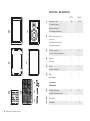
Contents / Kartoninhalt
1 2
3
4
5 6
7a
7b
7c
0
+
-
Aluminum frame
(including doglegs)
Aluminiumrahmen
(inkl. Rahmenklemmen)
Baffle with drivers and
crossover
Schallwand mit Chassis
und Frequenzweiche
Position template
Positionierungs-Schablone
Gasket
Dichtung
Foam
Schaumstoffmatte
Grille
Abdeckgitter
Accessories:
Zubehörteile:
Additional doglegs
zusätzl. Rahmenklemmen
Torx 15 Bit
Torx 20 Bit
1
2
3
4
5
6
7a
7b
7c
IP 17 IP 24
1 (6) 1 (10)
11
11
11
11
11
33
1 1
11

Dynaudio Installation Product 05
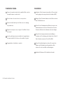
Unpacking Auspacken
• Klappen Sie die Oberseiten des Kartons auseinander und ent-
nehmen Sie vorsichtig den Inhalt. Wir empfehlen Ihnen, die
Verpackung bis zum Abschluss der Installation aufzubewahren.
• Überprüfen Sie alle Bestandteile auf Vollständigkeit (s. Seite 4).
• Entnehmen Sie den Lautsprecher aus der Kunststoffhülle.
• Entfernen Sie die Abdeckgitter vorsichtig vom Lautsprecher.
Ziehen Sie dazu gleichzeitig an den roten Folienstreifen.
• Lösen Sie die zehn äußeren Schrauben (Transportsicherung)
mit dem Torx 20 Bit. Bewahren Sie die Schrauben sorgfältig
auf, da sie später bei der Installation benötigt werden.
• Nehmen Sie die Schallwand aus dem Aluminiumrahmen und
bewahren Sie beides in der Verpackung auf, bis Sie mit dem
Wandeinbau beginnen können.
Hinweis: Siehe auch Kapitel Installation (ab Seite 10).
• Fold the top carton flaps back and carefully remove the
contents. We suggest that you keep the entire packaging
and all contents until the installation is complete.
• Check the contents; see previous page for a checklist.
• Remove the speaker from the plastic bag.
• Carefully remove the grille by lifting both ends of the red foil at
the same time.
• Un-tighten the transport screws (IP 17: 6, IP 24: 10), using the
Torx 20 bit, and place the screws into the accessory pack for
later use.
• Remove the baffle from the frame and, to avoid damage, keep
them in the supplied plastic bag (and preferably in the carton)
away from the work area until they are ready to be mounted.
Hint: Also reference the chapter titled “installation guide” (p. 10).

06 Dynaudio Installation Product
Safety Instructions Sicherheitshinweise
Bevor Sie mit der Positionierungs-Schablone die Wandaus-
sparungen freilegen, sollten Sie sich unbedingt vergewissern,
dass sich hier
keine anderen Installationen wie Rohre oder
Leitungen (Wasser, Gas, elektrischer Strom) befinden.
Im Interesse Ihrer Sicherheit sollten Sie mit einem Metalldetektor
den vorgesehenen Installationsort genau absuchen und so Ge-
fahren oder Schäden vermeiden. Grundsätzlich empfehlen wir
Ihnen die Beratung durch einen Fachmann.
Before producing the wall cut-out using the supplied template,
be sure that
no conflict with other in-wall installations will
occur (pipe work, air conditioning, power cabling, etc.).
In existing (retrofit) construction applications, Dynaudio recom-
mends using a stud-finding tool to map the wall construction
accurately, a pipe detector to scan the proposed installation
position and an electrical field detector to help avoid any risk of
electrical damage or shock.
Ideal Surrounding Einbauhinweise
Die Dynaudio IP Modelle wurden so abgestimmt, dass sie in ver-
schieden großen Wand-Hohlräumen ihr Klangpotenzial entfalten
können. Im Idealfall beträgt das Innenvolumen der Einbauöffnung
für den IP 24 über 30 Liter, für den IP 17 über 15 Liter.
Der Einbau in Hohlräume mit Luftschächten oder Rohren kann
aufgrund von Vibrationen die Klangqualität mindern.
Aus klanglichen Gründen sollten Sie die Platzierung in Raum-
ecken sowie im Übergangsbereich zu der Decke oder dem Fuß-
boden vermeiden. Wir empfehlen, die Lautsprecher im Abstand
von mindestens 0,5 m zur nächsten Wandecke einzubauen.
Um Bildstörungen durch magnetische Streufelder zu vermeiden,
sollten Sie einen Mindestabstand (0,15 m) zu einem Fernseh-
gerät beachten.
The IP Series models are designed to operate satisfactorily in a
wide range of cavity volumes, for the IP 17 this should ideally be
larger than 0.53 ft
3
(15 liters), while for the IP 24 it would be lar-
ger than 1.1 ft
3
(30 liters).
Avoid installing the speakers in the same cavity as any ducts, as
this may result in excessive rattle.
Placement near the inter
section of a wall/ceiling, wall/floor or in
a corner is not recommended, as it may detract from the opti-
mum sound quality. If possible, keep the speakers at a distance
greater than 20" (0.5 m) aw
ay from any wall edges.
Due to the residual magnetic field from the drivers, it is advisable
to position the speakers at a minimum distance of 6" (0.15 m)
from CRT televisions to avoid any adverse effect on the picture.

Dynaudio Installation Product 07
Positioning Positionierung
Allgemein
Die optimale Einbauhöhe des Lautsprechers orientiert sich an
der Hörposition der Personen. Der Hochtöner sollte im Idealfall
auf der Ohrhöhe des Hörers liegen.
Stereo
Der Abstand zwischen den Lautsprechern richtet sich nach der
Raumgröße und der Entfernung zum Hörer.
Grundregel: Der Abstand zwischen den beiden Lautsprechern
sollte etwas geringer sein als der Abstand der Lautsprecher
zum Hörer.
Heimkino
Der Abstand zwischen den Front-Lautsprechern sollte die Breite
des Fernsehbildschirms nicht unterschreiten.
Die optimale Platzierung zusätzlicher Heimkino-Lautsprecher
ergibt sich aus den Anforderungen des Surround-Systems.
General
The loudspeakers should ideally be placed with the tweeter
slightly above ear height at the listening position.
Stereo
The distance between the loudspeakers will depend on the size
of the room and the distance to the listening area.
The distance between both loudspeakers should be, in principle,
slightly less than the distance between the listener and the loud-
speakers.
Home Theatre
The front loudspeakers should not be placed closer together
than the width of the screen.
The surround loudspeakers’ positions shall be determined based
on the surround sound system.

08 Dynaudio Installation Product
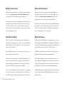
Optimizing the sound Klangoptimierung
Die Steifigkeit der Wand sowie die Dämpfung des Hohlraums
beeinflussen die Klangqualität eines gehäuselosen
Einbaulautsprechers.
Tipp 1: Die beigelegte Schaumstoffmatte bedämpft den Bereich
direkt hinter dem Lautsprecher. Grundsätzlich empfeh-
len wir, das Wandvolumen mit Dämmstoffen wie
Mineralwolle auszufüllen.
Wichtig: Bitte beachten Sie beim Einsatz der Dämmstoffe
geltende Gesundheits- und Sicherheitsvorschriften.
Tipp 2:
Für eine kräftige Basswiedergabe sollte jedoch das
Volumen im Bereich von etwa 0,5 m um den Laut-
sprecher möglichst keine Dämmstoffe enthalten (siehe
Abbildung). Für tiefere Bässe kann der dämmstofffreie
Bereich erweitert werden.
Tipp 3: Zusätzliche Verstrebungen und Verstärkungen im Hohl-
raum stabilisieren die Einbauwand und können so die
Klangqualität erhöhen.
Tipp 4: Mit einem Schalter (rechts neben dem Hochtöner)
lässt
sich der Wiedergabepegel der hohen Töne um 1,5 dB
erhöhen oder absenken.
The sound quality of any inwall loudspeaker system without a
cabinet enclosure is strongly influenced by the rigidity of the wall
and the damping of the internal wall cavity.
Tip 1: A foam piece is supplied to damp the area behind the
drive units. We recommend the whole section of the wall
cavity to be filled with wadding, such as mineral wool
used for insulation.
Important: You should check that the materials you use meet
the local fire and building regulations.
Tip 2:
To obtain a satisfactorily bass response, keep the
area of approx. 1.5 ft (0.5m) around the speaker
clear of wadding (see illustration). If more bass
is required, remove more wadding around the
speaker
Tip 3: To further optimize the sound quality of the speaker,
improve the stiffness of the wall by adding bracing
(inside the wall) around the speaker.
Tip 4: The tweeter level can be adjusted
± 1.5 dB with the
3-position switch placed on the right hand side of the
tweeter.

Dynaudio Installation Product 09
Customization Wohnraumanpassung
Die Aluminiumrahmen und die Abdeckgitter sind in seidenmat-
tem Weiß (RAL 9003) lackiert.
Rahmen und Gitter sind überlackierbar und können damit pro-
blemlos an eine individuelle Inneneinrichtung angepasst werden.
Die Schallwand und die Lautsprecherchassis dürfen
nicht lackiert
werden. Nehmen Sie das Abdeckgitter vor dem Lackieren ab.
Bei Malerarbeiten am Rahmen oder an der Wand empfehlen wir,
zum Beispiel mit einer Folie die Lautsprecher vor Farbspritzern
zu schützen.
Um Schäden zu vermeiden, sollten Sie die empfindlichen Mem-
branen der Hoch- und Tiefmitteltöner generell nicht berühren.
The grilles and frames of the Dynaudio IP Series loudspeakers are
painted in a white semi-matte (RAL 9003) finish.
Both may also be re-painted, and are ready to be refinished to
match your own interior décor scheme.
Do
not paint the baffle. Dynaudio recommends removing the
baffle before redecoration.
It is recommended that the baffle and drive units are protected
with e.g. a thin plastic foil when re-painting the frame or the sur-
rounding wall area.
Avoid touching the drive units, as inadvertent damage to such
might occur.

10 Dynaudio Installation Product
Installation Guide Installation
Hinweis: Als Zubehör ist für den IP 17 und den IP 24 ein Metall-
Einbaurahmen erhältlich, um bei einem Neubau oder einer extra
anzufertigenden Wandöffnung als Schablone und als mecha-
nische Rahmenverstärkung zu dienen. Für Installateure und
Handwerker erleichtert es dieser Rahmen, eine passende Wand-
öffnung vorzubereiten. Besonders geeignet ist der Einbaurahmen
z. B. für Zwischenwände, Fertigwände oder Rigips-Wände, wie
sie im Innenausbau verwendet werden.
Weitere Informationen erhalten Sie bei Ihrem Dynaudio
Fachhändler.
Installationsschritte:
Hint: A pre-construction bracket is available to better facilitate
new construction installations of the Dynaudio IP 17 and IP 24,
by working both as a template as well as a structural support
for the installation. The bracket serves as a guide to the dry
wall/sheet rock installer in order to help them ensure that the
loudspeaker cut-out openings are in the desired location upon
completion of the dry wall installation. The stamped steel bracket
is designed to fit between standard width studs in order to
accommodate the proper cutout for the loudspeaker opening.
For availability please check with your local Dynaudio dealer.
Installation:
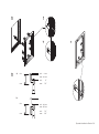
Entfernen Sie das Abdeckgitter vorsichtig. Ziehen Sie dazu an
den beiden roten Folienstreifen.
Lösen Sie die Rahmenschrauben (IP 17: 6 Stk., IP 24: 10 Stk.)
mit dem Torx 20 Bit. Bewahren Sie die Schrauben zur
weiteren Verwendung sorgfältig auf.
Entnehmen Sie die Schallw
and vorsichtig an den roten
Folienstreifen und legen sie zum Schutz in die Verpackung.
Beachten Sie die richtige Dichtungsposition auf der Rückseite.
Carefully remove front grille by lifting up strips.
Remove transport screws (IP 17: 6, IP 24: 10), using Torx 20
bit. Keep the screws in the accessory box for later use.
Carefully remove baffle by lifting up strips. Protect the baffle
in the original packing.
Mak
e sure the gasket on the rear side is in correct position.
1
2
3
4
2
3
4
1
Page is loading ...

12 Dynaudio Installation Product
Installation Guide Installation
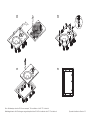
Einsetzen des Aluminiumrahmens in die Wandaussparung:
Lösen Sie die Schrauben der Rahmenklemmen, bis sie frei
beweglich sind.
Beachten Sie, dass alle Rahmenklemmen nach innen gedreht
sind. Setzen Sie den Rahmen mit der Unterseite zuerst ein.
Je nach Wandstärke gibt es zwei Möglichkeiten, die Rahmen-
klemmen auszurichten.
Wandstärken 0 – 40 mm: siehe Abbildung a)
Wandstärken 36 – 65 mm: siehe Abbildung b)
Drehen Sie die Rahmenklemmen nach außen, so dass sie
von hinten gegen die Wand drücken. Ziehen Sie die Klemmen
vorsichtig fest. Achten Sie darauf, dass sich dabei die
Klammern nicht verdrehen.
Putting the frame inside the wall cut-out:
Un-tighten the screws to bring the dogleg clamps from
‘locked’ position to ‘loose’ position.
Make sure all doglegs are in ‘loose’ position before frame is
positioned in the wall.
Depending on the wall thickness, two different options to
turn the doglegs are available.
Wall thickness of 0 – 40 mm (0 – 1.6"): refer to illustration a).
Wall thickness of 36 – 65 mm (1.4 – 2.6"): refer to illustration b).
Turn the doglegs so they press against the wall by carefully
tightening the screws. Place your hand inside the cavity to
control and assure the doglegs movement.
5
5a
5b
5c
6
5
5a
5b
5c
6

Dynaudio Installation Product 13
a)
b)
min.
max.
min.: 0 mm
max.: 40 mm
min.:
0 "
max.:
1.6 "
min.
max.
min.: 36 mm
max.: 65 mm
min.:
1.4 "
max.:
2.6 "
5
5a
5b
5c
6

14 Dynaudio Installation Product
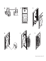
Installation Guide Installation
Verbinden Sie die Lautsprecheranschlüsse (Crossover) mit
den Ausgängen des ausgeschalteten Verstärkers (AMP).
Bringen Sie die Schaumstoffmatte auf der Rückseite hinter
dem Tief-/Mitteltöner an.
Setzen Sie die Schallwand mit der Oberseite zuerst in den
Aluminiumrahmen ein. Achten Sie darauf, dass Sie beim
Einsetzen die Kabel nicht einklemmen oder beschädigen.
Fixieren Sie die Lautsprechereinheit mit den Rahmen-
schrauben, die Sie zu Beginn gelöst haben (siehe Schritt 2).
Zum Festziehen verwenden Sie den Torx 20 Bit.
Setzen Sie das Abdeckgitter ein, indem Sie es zwischen
Rahmen und Schallwand vorsichtig andrücken. Bitte
drücken Sie nicht in der Mitte des Abdeckgitters.
Herzlichen Glückwunsch. Die Installation ist beendet.
Connect the speaker terminal to the amplifier. Make sure that
the amplifier power is switched off.
Put the foam on the rear side in its correct position.
Position the baffle with top first. Make sure not to damage
the speaker wire.
Tighten the transport screws, using the Torx 20 bit. (Screws
from step 2)
Insert the grille by pressing it carefully into the gap between
the frame and baffle. Don’t press in the middle of the grille.
Congratulations. Installation is complete.
7
8
9
10
11
12
7
8
9
10
11
12

Dynaudio Installation Product 15
7
8
9
10 11 12

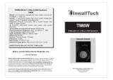
16 Dynaudio Installation Product
Maße
Aluminiumrahmen: a Höhe: 325 mm
b Breite: 225 mm
Wandaussparung: c Höhe: 295 mm
d Breite: 194 mm
Abdeckgitter: e Höhe: 285 mm
f Breite: 185 mm
Minimale Einbautiefe: 92 mm
Dimensions
Aluminum mounting frame: a Height: 12.80 " (325 mm)
b Width: 8.86 " (225 mm)
Cut Out: c Height: 11.61 " (295 mm)
d Width: 7.64 " (194 mm)
Grille: e Height: 11.22 " (285 mm)
f Width: 7.28 " (185 mm)
Minimum depth required: 3.62 " (92 mm)
c
a
ae
b
f
d
-
0
+
Dynaudio IP 17

a
c
a
e
b
f
d
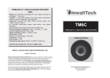
Dynaudio Installation Product 17
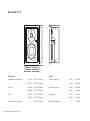
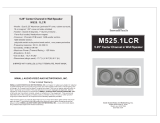
Maße
Aluminiumrahmen: a Höhe: 385 mm
b Breite: 286 mm
Wandaussparung: c Höhe: 351 mm
d Breite:
252 mm
Abdeckgitter:
e Höhe: 343 mm
f Breite: 244 mm
Minimale Einbautiefe: 92 mm
Dimensions
Aluminum mounting frame: a Height: 15.15 " (385 mm)
b Width: 11.25 " (286 mm)
Cut Out: c Height: 13.82 " (351 mm)
d Width: 9.92 " (252 mm)
Grille: e Height: 13.50 " (343 mm)
f Width: 9.60 " (244 mm)
Minimum depth required: 3.62 " (92 mm)
Dynaudio IP 24

18 Dynaudio Installation Product
Warranty Garantie
Dynaudio gewährt auf Lautsprecher eine Garantie von 5 Jahren.
Bitte beachten Sie regionale Sondervereinbarungen, um eine
über die gesetzliche Gewährleistungsfrist erweiterte Dynaudio
Garantie von 5 Jahren zu erhalten.
Diese Garantie erstreckt sich ausschließlich auf Material- und
Fertigungsmängel. Schäden, die durch unsachgemäßen Betrieb
oder defekte Verstärker entstanden sind, werden von der
Garantie nicht abgedeckt.
Als Nachweis für den Garantieanspruch gilt der Kaufbeleg. Die
Abwicklung von Reklamationen erfolgt in der Regel über Ihren
autorisierten Dynaudio Fachhändler.
Dynaudio provides a transferable five-year limited manufacturer’s
warranty.
This warranty only covers faults or defects in material and
production. Damage caused as a result of abuse, misuse or
defective electronics is not covered by the warranty.
All warranty claims must be accompanied by a copy of the
original purchase invoice and warranties are only valid in the
country or market of original origin or distribution. Should
warranty service be required, it must be arranged for in the
country of purchase by an authorized Dynaudio dealer.

IP 17 IP 24
Sensitivity (2.83 V / 1 m) 88 dB 90 dB
Empfindlichkeit (2,83 V/1 m)
IEC Long Term Power Handling 150 W 150 W
Belastbarkeit (Langzeitbelastung)
Impedance (nominal) 8 Ohms, linearized 4 Ohms, linearized
Impedanz (nominal) 8 Ohm, linearisiert 4 Ohm, linearisiert
Frequency Response (± 3 dB) 45 Hz – 23 kHz 40 Hz – 23 kHz
Frequenzbereich (± 3 dB)
Dimensions (W x H) 8.86 x 12.80 " 11.25 x 15.15 "
Abmessungen (B x H) 225 x 325 mm 286 x 385 mm
Technical Specifications / Technische Daten
Brochures / Broschüren
IP line Audience line Focus line Contour line Confidence line Subwoofer line

DYNAUDIO A/S
8660 Skanderborg
Denmark
Sales & Marketing
DYNAUDIO International GmbH
Ohepark 2
21224 Rosengarten
Germany
Phone +49 (0) 4108 - 41 80 - 0
© Dynaudio International GmbH, IP II Manual INT 0905. Item No. 455 910 A. Subject to change without notice. All text and image copyrights reserved.
www.dynaudio.com
-
 1
1
-
 2
2
-
 3
3
-
 4
4
-
 5
5
-
 6
6
-
 7
7
-
 8
8
-
 9
9
-
 10
10
-
 11
11
-
 12
12
-
 13
13
-
 14
14
-
 15
15
-
 16
16
-
 17
17
-
 18
18
-
 19
19
-
 20
20


Dynaudio IP 24 Owners Manual Installation Product
- Category
- Car speakers
- Type
- Owners Manual Installation Product
- This manual is also suitable for
Ask a question and I''ll find the answer in the document
Finding information in a document is now easier with AI
in other languages
- Deutsch: Dynaudio IP 24
Related papers
-
Dynaudio IP 24 User manual
-
-
-
-
-
-
-
-
-
Other documents
-
Canton InWall 845 Datasheet
-
Dali PHANTOM E-60 S Owner's manual
-
 Inwalltech M65.1C User manual
-
Atlantic Technology IN-NC-10 User manual
-
-
 Inwalltech M525.1LCR User manual
-
Atlantic Technology SYSTEM10SRDIPOLESURROUND User manual
-
 Inwalltech TM6W User manual
-
Audio Design ESX SIGNUM SXE42 User manual
-
 Inwalltech TM6C User manual


