Page is loading ...

Model No.
45-0299
OWNERS
MANUAL
CAUTION:
Read Rules for
Safe Operation
and Instructions
Carefully
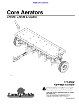
48" PLUG AERATOR
Assembly
Operation
Maintenance
Repair Parts
FORM NO. 48309 (4/25/07)PRINTED IN USA
the fastest way to purchase parts
www.speedepart.com
™

2
RULES FOR SAFE OPERATIONS
Remember, any power equipment can cause injury if operated improperly or if the user does not understand how to operate
the equipment.
CAUTION: VEHICLE BRAKING AND
STABILITY MAY BE AFFECTED WITH THE
ADDITION OF AN ACCESSORY OR AN
ATTACHMENT. BE AWARE OF CHANGING
CONDITIONS ON SLOPES.
LOOK FOR THIS SYMBOL TO POINT OUT
IMPORTANT SAFETY PRECAUTIONS. IT
MEANS -- ATTENTION! BECOME ALERT!
YOUR SAFETY IS INVOLVED.
Exercise caution at all times when using power equipment.
1. Read this owners manual carefully for operating and service instructions before attempting to assemble or operate this
equipment. Be thoroughly familiar with the proper use of this equipment.
2. Read the vehicle owners manual and vehicle safety rules, and know how to operate the vehicle before using this
equipment.
3. Never allow children to operate the tractor or plug aerator attachment, and do not allow adults to operate without proper
instructions.
4. This aerator attachment has sharp knife points. Always handle with care and wear substantial foot wear when operating
this aerator.
5. Do not allow anyone to ride or sit on plug aerator attachment frame or on towing vehicle.
6. Keep the area of operation clear of all persons, particularly small children, and also pets.
7. Alwaysbeginwiththetransmissioninrst(low)gearandengineatlowspeed,andgraduallyincreasespeedasconditions
permit.
8. The vehicle braking and stability may be affected with the attachment of this equipment. Be aware of changing conditions
on slopes. Refer to safety rules in the vehicle owner's manual concerning safe operation on slopes. STAY OFF OF STEEP
SLOPES.
9. Always operate up and down a slope, never across the face of a slope
10. This equipment should be operated at reduced speed on rough terrain, along creeks and ditches and on hillsides, to
prevent tipping and loss of control. Do not drive too close to a creek or a ditch.
11. Do not tow this equipment on a highway or any other public thoroughfare.
12. Follow the maintenance instructions as outlined in this owners manual.
1. Tray
2. Wheels (2)
3. Wheel Brackets (3)
4. Tongue
5. End Plates (2)
6. Lift Handle
Carton Contents
7. Hitch Bracket
8. Shaft
9. Middle Brace
10. Knives (32)
11. Double Spool Assemblies (4)
Hardware Pack (Shown next page)
LOOSE PARTS IN CARTON
1
2
7
8
6
9
4
5
3
11
10

3
HARDWARE PACKAGE CONTENTS
M 2 Jam Nut, 1/2"
N 32 Lock Washer, 5/16"
O 8 Flat Washer, 3/4" (2 for shims)
P 8 Spacer, 1/4" Long
Q 1 Spacer Tube, 3.90" Long
R 2 Spacer Tube, 1.00" Long
S 1 Spacer Tube, 2.38" Long
T 2 Spacer Tube, 5.29" Long
U 1 Shoulder Spacer
V 1 Handle Grip
W 8 Split Plastic Bearing
A 2 Hex Bolt, 1/2" x 3-1/2" Lg.
B 3 Hex Bolt, 1/4" x 1-3/4" Lg.
C 6 Hex Bolt, 3/8" x 1-1/4" Lg.
D 6 Hex Bolt, 3/8" x 1" Lg.
E 8 Hex Bolt, 5/16" x 3/4" Lg.
F 32 Carriage Bolt, 5/16" x 3/4"
G 1 Hitch Pin
H 1 Hair Cotter Pin
I 2 Nylock Jam Nut, 1/2"
J 12 Nylock Nut, 3/8"
K 40 Nylock Nut, 5/16"
L 3 Nylock Nut, 1/4"
Key Qty. Description Key Qty. Description
A C D E
B
F
H
G
I
J
K
L
N
O
P
Q
R
SHOWN FULL SIZE
NOT SHOWN FULL SIZE
S
VU
W
M
T

4
ASSEMBLY INSTRUCTIONS
TOOLS REQUIRED FOR ASSEMBLY
(2) 7/16" wrenches
(2) 1/2" wrenches
(2) 9/16" wrenches
(2) 3/4" wrenches or adjustable wrenches
Before assembling the aerator, lay out all the parts
and hardware as shown on previous pages.
CAUTION: POINTS OF AERATOR
KNIVES ARE SHARP! EXERCISE
CAUTION AT ALL TIMES WHILE
ASSEMBLING AND USING THE
AERATOR.
3. Assemble a wheel bracket to the middle hole in the
shaft so that the hub of the bracket faces the short end
of the shaft. Fasten the bracket to the shaft using a 1/4"
x 1-3/4" hex bolt and a 1/4" nylock nut. Tighten. See
gure2.
4. Pre-assemble a 3/8" x 1-1/4" hex bolt and a 3/8" nylock
nut to the smaller hole in the wheel bracket. Insert the
bolt from the hub side of the bracket. Do not tighten
till step 18.Seegure2.
FIGURE 2
FIGURE 1
FIGURE 3
5. Assemble a double spool assembly, a 5.29" long spacer,
another double spool assembly, a 1.00" long spacer and
a3/4"atwasherontotheshort end of the shaft. See
gure3.
1/4" x 1-3/4"
HEX BOLT
1/4"
NYLOCK NUT
3/8"
NYLOCK NUT
3/8" x 1-1/4"
HEX BOLT
SHORT END
OF SHAFT
5.29" LONG
SPACER
1.00" LONG
SPACER
3/4" FLAT
WASHER
SHORT END
5/16" x 3/4"
CARRIAGE BOLT
5/16" LOCK
WASHER
5/16"
NYLOCK NUT
SPLIT
BEARING
SPLIT
BEARING
1. Assemble eight aerator knives on the outside of each
double spool assembly. Rotate each knife to insert the
locking tab into the spool plate, then align the square
holes and secure with a 5/16" x 3/4" carriage bolt, a
5/16"lockwasher, anda 5/16"nylocknut. Seegure
1.
2. Push split plastic bearings into both ends of each double
spooltube.Seegure1.

5
6. Assemblea2.38"longspacer,a3/4"atwasher,the
middlebrace,a3/4"atwasheranda3.90"longspacer
onto the long end of the shaft. The bent lip of the middle
brace must face the short end of the shaft. Next assemble
a double spool assembly, a 5.29" long spacer, another
double spool assembly, a 1.00" long spacer and a 3/4"
atwasherontotheshaft.Seegure4.
FIGURE 5
FIGURE 6
8. Assemble a wheel to a wheel bracket using a 1/2" x 3-
1/2" hex bolt, a 1/2" jam nut and a1/2" nylock jam nut.
Adjust the nuts so that the wheel is held securely but
willspinfreely.Repeatonotherside.Seegure6.
FIGURE 7
9. Assemble the hitch bracket to the tongue using two 3/8"
x 1" hex bolts and 3/8" nylock nuts. Tighten.Seegure
7.
10. Assemble the hitch pin through the hitch bracket and
thetongue.Secureitwiththehaircotterpin.Seegure
7.
7. Rotate the wheel bracket fastened to the middle of the
shaft so that it is pointing upward. Assemble an end
plate,a3/4"atwasherandasecondwheelbracket
onto the long end of the shaft. Point this wheel bracket
asshowningure5.Secureittotheshaftusinga1/4"
x 1-3/4" hex bolt and 1/4" nylock nut. Tighten. Repeat
on short end of shaft.
FIGURE 4
2.38" LONG
SPACER
1.00" LONG
SPACER
3/4" FLAT
WASHER
MIDDLE
BRACE
3.90" LONG
SPACER
3/4" FLAT
WASHER
LONG END
OF SHAFT
5.29" LONG
SPACER
3/8" NYLOCK NUT
3/8" x 1"
HEX BOLT
HAIR COTTER PIN
HITCH
PIN
1/4" x 1-3/4"
HEX BOLT
1/4" NYLOCK NUT
3/4" FLAT
WASHER
MIDDLE WHEEL BRACKET
POINTING UP
1/2" NYLOCK JAM NUT
1/2" x 3-1/2"
HEX BOLT
1/2"JAM NUT

6
11. Assemble the tongue to the tray, placing the slot's locking
notch to the front. Use two 3/8" x 1" hex bolts, two 3/8"
x 1-1/4" hex bolts, four 1/4" long spacers, and four 3/8"
nylocknutsasshowningure8.Tighten.
12. Assemble two 3/8" x 1-1/4" hex bolts, four 1/4" long
spacers and two 3/8" nylock nuts to the holes on the
right side of the slot in the tray. Tighten.Seegure8.
FIGURE 10
13. Place the tray between the end plates. Temporarily
insert three 5/16" x 3/4" hex bolts to hold the tray and
end plates together at the corners. Leave one upper
cornerempty.Seegure9.
14. Rotate the middle brace up against the tongue, aligning
it with the holes that are closest to the slot in the tray.
Fasten the brace to the tongue using two 3/8" x 1" hex
bolts and 3/8" nylock nuts. Do not tighten till step 18.
Seegure9.
FIGURE 8
FIGURE 9
15. Fasten the end plates to the corners of the tray using
eight 5/16" x 3/4" hex bolts and 5/16" nylock nuts. Do
not tighten till step 18.
3/8" x 1"
HEX BOLT
3/8" x 1-1/4"
HEX BOLT
1/4" LONG
SPACERS
3/8" NYLOCK NUT
3/8" x 1-1/4"
HEX BOLT
5/16" x 3/4"
HEX BOLT
(Temporary)
3/8" x 1"
HEX BOLT
MIDDLE
BRACE
3/8" NYLOCK NUT
5/16" x 3/4"
HEX BOLT
5/16" NYLOCK NUT

7
16. Place the lift handle through the slot in the tray. Fasten
the lift handle to the smaller, inner hole in the middle
wheel bracket using the bolt and nut which you pre-
assembledearlier(gure2).Fastenthelifthandleto
the larger, outer hole in the wheel bracket using a 3/8"
x 1-1/4" hex bolt, the shoulder spacer, and a 3/8" nylock
nut. Tighten both nylock nuts.Seegure11.
17. Pushthegripontothelifthandle.Seegure11.
FIGURE 11
FIGURE 12
GRIP
3/8" x 1-1/4"
HEX BOLT
3/8" NYLOCK NUT
SHOULDER
SPACER
PRE-ASSEMBLED
NUT AND HEX BOLT
18. Perform the following steps in sequence to assure secure
lockingofthelifthandle.Refertogure12.
a. Turn the aerator upright, then place the lift handle
into the transport locking notch at the front end of
the slot in the tray.
b. Stand on the right side of the aerator and push
against the tray, which will force the lift handle over
to the right side of the notch.
c. Keep the tray and lift handle in this alignment and
tighten the eight bolts at the corners of the tray.
d. Tighten the two bolts which fasten the middle brace
to the tray.
e. After performing these steps, some effort should
be required to shift the lift handle from the transport
locking notch over into the slot to lower the aerator.
When the aerator is raised, the lift handle should
spring back over into the transport locking notch.
c
c
c
c
d
b
a
PUSH AGAINST
THIS SIDE
CAUTION: The Lift Handle can drop
to the rear unexpectedly. It will not lock
securely in transport position until step
"c" below is completed.

8
MAINTENANCE
1. Plugger points can periodically be sharpened with a small
grinder to maintain good penetration. Points should be
removed to sharpen. Follow original angle and contour
of points when grinding.
2. For storage, clean the aerator and lightly oil all exposed
metal parts to prevent rust.
1. Mow lawn and remove loose clippings prior to use of
lawn aerator.
2. Start tractor engine with controls in neutral and place
throttle at slow engine speed.
3. Engage shift lever at lowest possible forward speed
and lower aerator, allowing plugger points to enter the
ground. Increase speed as conditions permit.
4. Aerate in the straightest line possible, making overlapping
passes to increase the plugger point pattern.
5. Avoid extremely sharp turns with plugger points
engaged in ground to prevent damage to lawn.
6. DO NOTcrossoverwalksordriveswithoutrstraising
the aerator to the transport position.
7. On sloped lawns, always aerate in an up and down
direction. DO NOT attempt to follow the contour of the
ground.
8. To increase the depth of plugger point penetration,
up to 140 lbs. of weight, such as bags of sand or (4)
concrete blocks, may be added to the tray. The weight
can be secured to the tray with ties or straps fastened
to the front and rear of the tray. Fasten so that the ties
or straps cannot become entangled on rotating parts.
10. If the ground is extremely hard and dry, it is recommended
that it be sprinkled or watered down for one or two hours
prior to aerating.
11. DO NOT attempt to aerate if ground is too wet,
(muddy).
12. Do to small rocks and gravel which are normally present
in aerated soil plugs, it is recommended that the plugs be
raked; otherwise damage to the lawn mower blades may
arise, especially when reel type mowers are used.
OPERATION
Aerating means pulling small soil plugs, ranging up to three
inches in length, from the soil to create small reservoirs that
will bring oxygen, fertilizer and water down into the roots.
For best aerator performance, the following lawn preparations
and operating procedures are recommended.
CAUTION: POINTS OF AERATOR
KNIVES ARE SHARP! EXERCISE
CAUTION AT ALL TIMES WHILE
USING THE AERATOR.
CAUTION: TO PREVENT INJURY,
DISMOUNT FROM TRACTOR TO
RAISE OR LOWER AERATOR
CONTAINING ADDED WEIGHT.
LUBRICATION
1. Oil the spool assemblies and shaft as needed.
2. Oil the wheel hubs as needed.

9
NOTES

10
REPAIR PARTS FOR 48" PLUG AERATOR MODEL 45-0299
1
2
4
3
3
5
6
7
8
8
9
9
9
10
10
14
19
21
22
22
23
23
24
26
25
27
27
27
27
28
28
28
28
28
28
28
31
32
29
30
33
34
35
17
17
17
17
17
17
12
12
12
12
13
18
12
13
13
12
13
17
27
10
27
28
30
36
20
21
37
32

REPAIR PARTS FOR 48" PLUG AERATOR MODEL 45-0299
REF. PART QTY. DESCRIPTION
NO. NO.
1 24625 1 Tray (48")
2 24623 1 Middle Brace
3 24619 2 End Plate
4 24624 1 Lift Handle
5 24103 1 Tongue
6 24626 1 Shaft (48")
7 23687 1 Hitch Bracket
8 46503 2 Wheel
9 63931 3 Wheel Bracket Assembly
10 63929 4 Spool Assembly (Double)
12 43087 6 Hex Bolt, 3/8-16 x 1-1/4" Long
13 43001 6 Hex Bolt, 3/8-16 x 1" Long
14 23625 8 Spacer, 1/4" Long
17 HA21362 12 Nylock Nut, 3/8-16 Thd.
18 44685 1 Spacer, Shoulder
19 43182 8 Hex Bolt, 5/16-18 x 3/4" Long
20 43086 32 Lock Washer, 5/16"
21 47810 40 Nylock Nut, 5/16-18 Thd.
22 1509-69 3 Hex Bolt, 1/4-20 x 1-3/4" Long
REF. PART QTY. DESCRIPTION
NO. NO.
23 47189 3 Nylock Nut, 1/4-20 Thd.
24 46526 2 Hex Bolt, 1/2-13 x 3-1/2" Long
25 43019 2 Hex Jam Nut, 1/2-13 Thd.
26 48115 2 Nylock Jam Nut, 1/2" Thd.
27 43009 8 Flat Washer, 3/4"
28
741-0439A
8 Split Bearing, 3/4"
29 44474 1 Spacer, 2.38" Long
30 44500 2 Spacer, 1.00" Long
31 46537 1 Spacer, 3.90" Long
32 47675 2 Spacer, 5.29" Long
33 47707 1 Grip
34 47623 1 Hitch Pin, 3/8" Flat Head
35 43343 1 Hair Cotter Pin, 1/8"
36 24924 32 Knife, Aerator
37 43080 32 Carriage Bolt, 5/16-18 x 3/4"
48309 1 Owners Manual
the fastest way to purchase parts
www.speedepart.com

12
© 2002 Agri-Fab, Inc.
REPAIR PARTS
Agri-Fab, Inc.
303 West Raymond
Sullivan, IL 61951
217-728-8388
www.agri-fab.com
the fastest way to purchase parts
www.speedepart.com
This document (or manual) is protected under the U.S. Copyright Laws and the copyright laws of foreign countries,
pursuant to the Universal Copyright Convention and the Berne convention. No part of this document may be reproduced
or transmitted in any form or by an means, electronic or mechanical, including photocopying or recording, or by any
information storage or retrieval system, without the express written permission of Agri-Fab, Inc. Unauthorized uses and/or
reproductions of this manual will subject such unauthorized user to civil and criminal penalties as provided by the United
States Copyright Laws.
/