Page is loading ...

Meade Instruments Corporation
Instruction Manual
LXD55-Series Telescopes


Telescope Features ...................................................... 4
Autostar Features .......................................................... 9
Getting Started ..............................................................11
Unpacking and Assembly..........................................11
How to Assemble Your Telescope ............................11
Balancing the Telescope ..........................................13
Aligning the Viewfinder..............................................14
Choosing an Eyepiece..............................................14
Observing By Moving the Telescope Manually ........15
Activate the Arrow Keys............................................16
Slew Speeds ............................................................16
Observe the Moon ....................................................17
Tracking Objects ......................................................17
Setting the Polar Home Position ........................17
Observe a Star Using Automatic Tracking ..........18
Using Autostar's GO TO Capabilities..................18
Moving Through Autostar’s Menus......................19
Initializing Autostar ..............................................19
Training the Drive ................................................20
Easy Alignment ........................................................21
Go To Saturn ............................................................21
Using the Guided Tour..............................................22
Basic Autostar Operation................................................23
Autostar Navigation Exercise....................................23
Entering Data into Autostar ......................................24
Navigating Autostar ..................................................24
Autostar's Menus............................................................25
Object Menu..............................................................26
Event Menu ..............................................................27
Glossary Menu..........................................................27
Utilities Menu ............................................................27
Setup Menu ..............................................................28
Useful Autostar Features................................................32
Adding Observing Sites ............................................32
Using Autostar to Find Objects Not in the Libraries....33
Observing Satellites..................................................34
Landmarks ................................................................34
To Check on Available Memory ................................35
Photography ..................................................................36
Optional Accessories......................................................37
Maintenance ..................................................................39
Specifications ................................................................45
Appendix A: Celestial Coordinates ................................48
Setting Circles ....................................................48
Locating the Celestial Pole..................................49
One- And Two-Star Polar Alignment....................49
Appendix B: Enhancing Pointing Precision....................50
The Polar Alignment Viewfinder ..........................50
Axis Alignment Method 1 ....................................50
Axis Alignment Method 2 ....................................53
Appendix C: Latitude Chart............................................54
Appendix D: EC Handbox ..............................................55
Appendix E: Mounting the Model SC-8 Optical Tube ....59
Appendix F: Basic Astronomy ........................................60
CONTENTS
WARNING!
Never use a Meade
®
LXD55-Series
Telescope to look at the Sun! Looking at or
near the Sun will cause instant and irre-
versible damage to your eye. Eye damage is
often painless, so there is no warning to the
observer that damage has occurred until it is
too late. Do not point the telescope or its
viewfinder at or near the Sun. Do not look
through the telescope or its viewfinder as it is
moving.
Children should always have adult
supervision while observing.
CAUTION: Use care to install batteries in
the orientation indicated by the illustration in
the battery slots of the battery holder. Follow
battery manufacturer's precautions. Do not
install batteries backwards or mix new and
used batteries. Do not mix battery types. If
these precautions are not followed, batteries
may explode, catch fire, or leak. Improperly
installed batteries void your Meade warranty.
® The name "Meade" and the Meade logo are trademarks
registered with the U.S. Patent Office and in principal coun-
tries throughout the world. "LXD55" and "Autostar" are
trademarks of Meade Instruments Corporation.
"Easy Align" U.S. patent 6,392,799 and other patents pend-
ing.
Intelligent Network Architecture to Facilitate Parallel Task
Management U.S. patent 6,304,376
© 2003 Meade Instruments Corporation.

TELESCOPE FEATURES
4
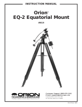
Fig. 1a:The LXD55-Series Telescope Optical Assembly (Schmidt-Newtonian model with Autostar handbox shown;
Electronic Controller model users, see Appendix D, page 55).
Fig. 1c:The LXD55-Series Tripod
B
Cg
d
f
I
1)
1#
1$
e
H
J
1!
1@
3%
3&
4)
3^
3(
Fig. 1b: Close up of Focuser and Viewfinder Assembly,
Scmidt-Newtonian shown. (See Fig. 1a for overview.) For
a close up of the refractor focuser assembly, see Fig. 10b,
page 13.
B
C
g
d
f
I
e
H
1%
1^
3*
1#

5
Fig. 1e:The LXD55-Series Computer Control Panel (see 2$ above).
Fig. 1d: The LXD55-Series Mount.
2!
2@
1&
1*
1(
2#
2$
2%
2^
2^
2*
2(
2&
3)
3!
3@
3#
3$

LXD55-Series:Your Personal
Window to the Universe
The Meade LXD55-Series models are versatile, high-resolution telescopes. Supplied
with either an Electronic Controller or an Autostar handbox, the
LXD55-Series models
offer unmatched mechanical and electronic performance.
The
LXD55-Series telescopes reveal nature in an ever-expanding level of detail.
Observe the feather structure of an eagle from 50 yards or study the rings of the plan-
et Saturn from a distance of 800 million miles. Focus beyond the Solar System and
observe majestic nebulae, ancient star clusters, and remote galaxies. Meade
LXD55-
Series telescopes are instruments fully capable of growing with your interest and can
meet the requirements of the most demanding advanced observer.
Refer to Figures 1a through 1e for the following features:
B Eyepiece Thumbscrew: Tightens the eyepiece (see d) in place. Tighten to a
firm feel only.
C Eyepiece Holder: Holds eyepiece in place. Holders supplied for both 1.25" and
2" eyepieces.
Diagonal (not shown, achromatic refractor models only): Provides a more
comfortable right-angle viewing position. Slide the diagonal directly into the eye-
piece holder (see
c) and tighten the thumbscrew on the eyepiece holder to a
firm feel only. See page 13 for a photo and more information.
D Eyepiece: Place the supplied Super Plössl 26mm eyepiece into the eyepiece
holder or the diagonal and tighten in place with the eyepiece thumbscrew (see
b). The eyepiece magnifies the image collected in the optical tube.
8 x 50mm (achromatic refractors models) or 6 x 30mm (Schmidt-Newtonian
models) Viewfinder: A low-power, wide-field sighting scope with crosshairs that
enables easy centering of objects in the telescope eyepiece (see
d).
Viewfinder Collimation Screws (6): Use these screws to adjust the alignment of
the viewfinder.
Viewfinder Front Cell and Locking Ring: Adjust the front cell to focus the
viewfinder. See step 3, page 14 for more details. The viewfinder is supplied with
a small dust cover placed over the front cell.
Viewfinder Bracket: Holds the viewfinder in place.
Focus Knobs:
Moves the telescope’s focuser drawtube in a finely-controlled
motion
to achieve precise image focus. The LXD55-Series telescopes can be
focused on objects from a distance of about 75 ft. to infinity. Rotate the focus
knobs to focus on objects.
Corrector/Dust Cover: Place the dust cover (not visible in photo) over the cor-
rector when storing the telescope.
Note: The dust cover should be replaced after each observing session
and the power turned off to the telescope. Allow time for any dew that
might have collected during the observing session to evaporate prior to
replacing the dust cover.
1) Optical Tube: The main optical component that gathers the light from distant
objects and brings this light to a focus for examination through the eyepiece.
1! Cradle Assembly: Attaches to mount base. See 1# and 1$.
1@ Autostar: See pages 9 and 10 for a description of features.
1# Cradle Ring Lock Knobs (2) and Washers (2): Slide washers onto lock knobs
before inserting.
Tighten to a firm feel to secure the optical tube in place.
1$ Cradle Rings (2): Part of the cradle assembly (see 1!); h
old the optical tube firm-
ly in place.
Caution:
Using products
other than standard Meade
accessories may cause dam-
age to the telescope’s inter-
nal electronics and may void
the Meade warranty.
6
d Want to learn more
about the eyepieces
available for your
LXD55-Series tele-
scope?
See OPTIONAL
ACCESSORIES
, page
37.
e Want to learn more
about aligning the
viewfinder? See page
14.
1! Want to learn more
about assembling your
telescope?
See
ASSEMBLING
YOUR TELESCOPE
,
page 11.
h Want to learn more
about attaching the
viewfinder? See page
12.
1@ EC Handbox users,
see Appendix D, page
55, for more informa-
tion.

7
1% Viewfinder Bracket Screws (2): Tighten to a firm feel to hold viewfinder secure-
ly in place (see
E). See page 12 for more information.
1^ Focus Lock Knob: Designed to prevent the focuser drawtube from moving when
a heavy accessory, such as a camera, is attached to the focuser assembly. For
normal observing with an eyepiece and diagonal, it is not necessary to use the
lock knob.
1& Dec. Lock: Controls the manual movement of the telescope. Turning the Dec.
lock counterclockwise unlocks the telescope enabling it to be freely rotated by
hand about the Dec. axis. Turning the Dec. lock clockwise (to a firm feel only)
tightens the lock and prevents the telescope from being moved manually, but
engages the Dec. motor drive (see
3$) for Autostar operation.
1* Polar Viewfinder Cap: Remove this cap when using the polar viewfinder (see 2().
1( Declination (Dec.) Setting Circle: See APPENDIX A, page 48, for more informa-
tion.
2) Counterweight Shaft Base: Thread, along with the shaft, to the mount. See
page 11 for more information.
2! Counterweight and Counterweight Lock Knob: Counterbalances the weight of
the optical tube, and adds stability to the mount. Tighten the lock knob on the side
of the counterweight to a firm feel to prevent the weight from sliding on the shaft.
2@ Counterweight Shaft: Slide the counterweight onto this shaft (see 2!).
2# Counterweight Safety Cap: Prevents the counterweight from accidentally slip-
ping off the end of the counterweight shaft.
2$ Computer Control Panel (see Fig. 1e):
A. Handbox (HBX) Port: Plug the Autostar or EC handbox coil cord (10,
Fig. 2) into this port.
B. 12v DC Power Connector: Plug the battery pack into this connector.
The telescope assembly also may be powered from either a 12v DC
auto cigarette lighter plug using the optional #607 Cigarette Lighter
Adaptor or from a standard 115v AC home outlet using the optional
#547 Power Adapter with Cable or #547F Power Adapter for 220v out-
lets. See
OPTIONAL ACCESSORIES, page 38.
C. LED: Illuminates when power is supplied to the Autostar or EC hand-
box and the telescope’s motor drive.
D. ON/OFF Switch: Turns the Computer Control Panel and Autostar ON
or OFF.
E. AUX Port:
Provides connection for current and future Meade accessories.
See
OPTIONAL ACCESSORIES, page 38.
F. Dec Port:
Plug the coil cord from the Dec. motor assembly into this port
for Autostar to control the motor drive.
2% R.A. Motor Drive Assembly: Controlled by Autostar or EC handbox. Moves the
optical tube along the R.A. axis. The R.A. Lock (see
3#) must be tightened to a
firm feel in order for the R.A. motor to operate.
2^ Latitude Adjustment (2): Sets the latitude of your observing location. The two T-
handle screws work in a "push - pull" operation—as you tighten one, loosen the
other. The T-handle above the star marking on top of one of the tripod legs is the
North T-handle screw (South in the Southern Hemisphere). The leg marked with
a star must be pointed North (South in the Southern hemisphere) during the polar
alignment procedure.
2& Fine Azimuth Control Knobs: Fine tune the side-to-side movement of the tele-
scope when centering Polaris in the telescope eyepiece or when using the polar
alignment viewfinder (see
2().
2* Latitude Dial: Set the latitude of the observing site on this dial using the latitude
T-handle screws. For more information see Step 6, page 12.
Caution When loosening
the Dec. lock, be sure to
support the optical tube
(18, Fig. 1a).The weight of
the tube could cause the
tube to swing suddenly.
2* Want to learn more
about setting the lati-
tude dials?
See
STEP 6, page 12.

8
2( Polar Alignment Viewfinder: Allows you to precisely polar align the telescope.
Useful when performing astrophotography. See page 50.
3) Polar Alignment Viewfinder Reticle and LED Knob: Rotate the knob to switch
on or off the LED that illuminates the reticle within the polar alignment finder. Be
sure to turn off the LED when finished with the polar viewfinder. Powered by (fac-
tory-supplied) batteries contained within.
3! Right Ascension (R.A.) Setting Circle: See APPENDIX A, page 48, for more
information.
3@ R.A. Setting Circle Lock Knob: Rotate the knob to lock the R.A. Setting Circle
(see
3!) in place.
3# R.A. Lock: Controls the manual movement of the telescope. Turning the R.A.
lock counterclockwise unlocks the telescope enabling it to be freely rotated by
hand about the R.A. axis. Turning the R.A. lock clockwise (to a firm feel only)
tightens the lock and prevents the telescope from being moved manually, but
engages the R.A. motor drive (see
2%) for Autostar or EC handbox operation.
3$ Dec. Motor Drive Assembly: Controlled by Autostar or the EC handbox. Moves
the optical tube along the Dec. axis. The Dec. Lock (see
1&) must be tightened to
a firm feel in order for the Dec. motor to operate.
3% Tripod Leg Adjustment Knobs (3): Tighten to a firm feel to secure tripod legs.
3^ Variable Height Tripod Legs (3): Supports the telescope mount. Note that one
legs has a star stamped on top of it. This leg must be pointed North (South in the
Southern hemisphere) during the alignment procedure. The mount attaches to
the top of the tripod.
3& Accessory tray: Set extra eyepieces and other accessory on this convenient
tray.
3* Tripod Leg Braces (3): Make the tripod more secure and stable. See Fig. 3.
3( Accessory Tray Thumbscrew: Attach on the top side of the tray and tighten to a
firm feel to secure the tray to the tripod and keep the tripod stable. See
HOW TO
ASSEMBLE YOUR TELESCOPE, page 11 for more information.
4) Tripod Leg Lock Knobs (one on each leg): Loosen these knobs to slide the
inner leg extension. Tighten the knobs to a firm feel to lock in the height of the tri-
pod.
4! Battery Pack and holder (see Fig. 1f): Plug into the 12v DC power connector
(B, Fig. 1e) of the computer control panel. Insert 8 (user-supplied) D-cell batter-
ies to power motor drives and Autostar handbox.
Join an Astronomy Club, Attend a Star Party
One of the best ways to increase your knowledge of astronomy is to join an astronomy
club. Check your local newspaper, school, library, or telescope dealer/store to find out if
there’s a club in your area.
At club meetings, you will meet other astronomy and Meade enthusiasts with whom you
will be able to share your discoveries. Clubs are an excellent way to learn more about
observing the sky, to find out where the best observing sites are, and to compare notes
about telescopes, eyepieces, filters, tripods, and so forth.
Often, club members are excellent astrophotographers. Not only will you be able to see
examples of their art, but you may even be able to pick up some “tricks of the trade” to
try out on your
LXD55-Series telescope. See page 36 for more information about pho-
tography with the
LXD55-Series.
Many groups also hold regularly scheduled Star Parties at which you can check out and
observe with many different telescopes and other pieces of astronomical equipment.
Magazines such as Sky & Telescope and Astronomy print schedules for many popular
Star Parties around the United States and Canada.
LXD55 TIPS
Fig. 1f:The LXD55-Series Battery
Pack and holder.
4!
Caution: Use care to
install batteries as indicat-
ed by the battery com-
partment. Follow battery
manufacturer's precau-
tions. Do not install batter-
ies backwards or mix new
and used batteries. Do
not mix battery types. If
these precautions are not
followed, batteries may
explode, catch fire, or
leak. Improperly installed
batteries void your Meade
warranty. Always remove
the batteries if they are
not to be used for a long
period of time.
2( Want to learn more
about the polar align-
ment viewfinder?
See the The Polar
Alignment Viewfinder,
page 50.
4! Want to learn how to
install the batteries?
See step 12, page 13.

9
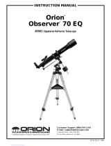
Fig. 2: The Autostar Handbox.
Tour the Cosmos with Just the Push of a Button
Control of most LXD55-Series telescope models (excluding the EC models; see mar-
gin note) is through the operation of Autostar. Nearly all functions of the telescope are
accomplished with just a few pushes of Autostar’s buttons. Some of the major fea-
tures of Autostar are:
■ Automatic GO TO capability: Automatically move the telescope to any of the
more than 30,000 objects stored in the object library.
■ Take a guided tour of the best celestial objects to view on any given night of the
year.
■ Download the latest satellite data and software revisions directly from the Meade
website (www.meade.com) and share software with other Autostar enthusiasts.
Requires optional #505 AstroFinder™ Software and Cable Connector Kit. See
OPTIONAL ACCESSORIES, page 38.
■ Access a glossary of astronomical terms.
■ Fully automatic tracking of celestial objects.
Features
The Autostar Computer Controller provides control of virtually every telescope func-
tion within a compact handbox. Autostar has soft-touch keys designed to have a pos-
itive feel. The LCD (Liquid Crystal Display) is backlit with a red LED (Light Emitting
Diode) for easy viewing in the dark. The backlit display, key arrangement, and
sequential menu structure make Autostar extremely user friendly.
B 2-Line LCD Display: This screen displays Autostar's menus and other informa-
tion about the telescope.
■ Top line: Lists the primary menu.
■ Bottom line: Contains other menus that may be selected, menu options, tele-
scope status, or information about a function that is currently being performed.
C ENTER Key: Press to go to the next menu level or to choose an option in a
menu. The ENTER key is similar to the RETURN or ENTER key on a computer.
See
MOVING THROUGH AUTOSTAR'S MENUS, page 19 and AUTOSTAR’S MENUS,
page 25.
AUTOSTAR FEATURES
Note: Autostar does not
require batteries; the tele-
scope’s batteries supply
power to Autostar.
Important Note: The
model SN-6EC, model
SN-8EC, and model AR-
5EC are equipped with an
Electronic Controller
handbox, rather than the
Autostar Handbox.
Several of the following
procedures, such as
Tracking Objects and
Initializing Autostar (to
name but a few), are rele-
vant only to models
equipped with the
Autostar handbox and do
not apply to the EC mod-
els. For more information
about the EC handbox,
see
APPENDIX D: EC
HANDBOX
, page 55.

10
Note: If ENTER is pressed for two seconds or more and then released,
Autostar emits a beep and “ENTER to Sync” is displayed. "ENTER to
Sync" may be used only after your telescope has been aligned and is
pointing at an object. See page 30 for more details.
MODE Key: Press to return to the previous menu level. The top menu level is
“Select Item." The MODE key is similar to the ESCAPE key on a computer.
Note: Pressing MODE repeatedly while in the “Select Item” level moves
Autostar to the topmost screen: “Select Item: Object.”
Note: If MODE is pressed and held for two seconds or more, information
about the telescope's status displays.When the status displays, press the
Scroll keys (7, Fig. 2) to display the following information and more:
■
Right Ascension and Declination (astronomical) coordinates
■ Altitude (vertical) and Azimuth (horizontal) coordinates
■ Local Time and Local Sidereal Time (LST)
■ Timer and Alarm Status
Press MODE again to return to the previous menu.
E GO TO Key: Press to slew (move) the telescope to the coordinates of the cur-
rently selected object. While the telescope is slewing, the operation may be
aborted at any time by pressing any key except GO TO. Pressing GO TO again
resumes the slew to the object. Also, press GO TO after a slew is completed to
activate a "spiral search."
F Arrow Keys: Press to slew the telescope in a specific direction (up, down, left,
and right), at any one of nine different speeds. See
SLEW SPEEDS, page 16.
G Number Keys: Press to input digits 0 to 9. When data is not being entered, the
Number keys can be used to change the slew speed. To operate, just press a
number key (1 is the slowest speed, 9 is the highest speed). Press the Number
key "0" to turn on and off the red utility light on the top of the handbox.
H Scroll Keys: Press to access options within a selected menu. The menu is dis-
played on the first line of the screen. Options in that menu are displayed, one at
a time, on the second line. Press the Scroll keys to move through the options.
Press and hold a Scroll key to move quickly through the options.
I ? Key: Press to access the "Help" function. Help provides on-screen information
on how to accomplish whatever task is currently active.
Hold down the ? key and then follow the prompts on the display to access details
of Autostar functions in the Help feature. The Help system is essentially an on-
screen instruction manual.
If you have a question about an Autostar operation, e.g., INITIALIZATION,
ALIGNMENT, etc., hold down the ? key and follow the directions that scroll on the
second line. When satisfied with the Help provided, press MODE to return to the
original screen and continue with the chosen procedure.
J Coil Cord Port: Plug one end of the Autostar coil cord (see 1)) into this port
located at the bottom of the Autostar handbox and the other end into the HBX
port of the computer control panel (A, Fig. 1e).
1) Coil Cord: Plug one end of the Autostar coil cord into the HBX port (A, Fig. 1e)
of the computer control panel of the telescope and the other end into the Autostar
coil cord port (See
J).
1! RS232 Port: Plug in RS232 connections for downloading and connecting to com-
puter. Useful for downloading the latest satellite data and software revisions
directly from the Meade website (www.meade.com) Requires optional #505
AstroFinder™ Software and Cable Connector Kit. See
OPTIONAL ACCESSORIES,
page 38.
1@ Utility Light: Use this built-in red light to illuminate star charts and accessories
without disturbing your eye's adaptation to darkness. Press "0" to turn the light
on and off.
E Want to learn more
about using the GO TO
function? See page
21.
Want to learn how to
perform a spiral
search? See page 21.
Definitions:
"Slew" means to move the
telescope's optical tube to
a selected object.
Tip:
If the "ENTER to Sync"
feature is accessed by
mistake, press MODE
to return to the previous
screen.

11
As you unpack your telescope, carefully note the following parts. The assembly is
shipped in separate boxes.
Telescope Assembly
■ Equatorial mount with polar alignment finder
■ Heavy duty, adjustable aluminum tripod with leg braces, three tripod leg lock
knobs, and a captive mount locking knob
■ Complete optical tube assembly including primary mirror with dust cover and a
rack-and-pinion focuser and eyepiece holders for both 1.25" and 2" eyepiece
holders, tube cradle assembly with two rings and two lock knobs
■ Super Plössl (SP) 26mm eyepiece
■ Counterweight and counterweight shaft. The 8" and 10" models include extra
counterweights.
■ 8 x 50mm (achromatic refractors models) or 6 x 30mm (Schmidt-Newtonian
models) viewfinder
Motor Assembly
■ Factory-mounted dual electronic motor drive assembly
■ Autostar handbox, detachable coil cord, or Electronic Controller
■ Battery pack and holder
Accessories
■ Accessory shelf with mounting knob, hex keys, LXD55-Series T-Adapter (includ-
ed with Schmidt-Newtonian models only)
How to Assemble Your Telescope
The giftboxes contain the optical tube assembly and the tripod with the equatorial
mount. The accessories are located within compartments custom-cut into the styro-
foam block inserts.
1. Remove the components from the giftboxes: Remove and identify the tele-
scope’s equipment. Refer to Figures 1a through 1f for images of the parts and
the overall assembly of your telescope. When removing the tripod from the gift-
box, hold the assembly parallel (horizontal) to the ground or the inner tripod leg
extensions will slide out as they are not locked in place.
2. Adjust the tripod legs. Spread the tripod legs as far as they will open, so that
the leg braces are taut. See Fig. 3.
3. Attach the accessory shelf to the tripod: Remove the mounting knob from the
center of the leg braces (39, Fig. 1c). Place the triangular accessory shelf on top
of the leg braces so that each corner of the triangle lies over a leg brace. Notice
that there is protrusion on each leg brace. There is a corresponding slot for each
protrusion on the accessory tray. See Fig. 4. Line up the slots with the protrusions
and slide the protrusions through the slots to hold the tray in place. Next, slide
the mounting thumbscrew through the hole in the center of the brace and tighten
to a firm feel.
4. Attach mount to tripod base: Place the mount over the base of the tripod with
the computer control panel positioned above the tripod leg marked with a star and
with the protrusion on top of the tripod's base positioned between the fine
azimuth control knobs. See Fig. 5. Back off the azimuth control knobs wide
enough for protrusion to fit between them. Slide the hole in the center of the
underside of the mount onto the captive mount locking bolt in the center of the
base and tighten it by turning the knob below the base. Tighten to a firm feel.
5. Attach the counterweight(s) to the counterweight shaft: Place the counter-
weight shaft base (20, Fig. 1d) over the threaded end of the shaft (22, Fig. 1d).
Thread the shaft and base assembly into the hole beneath the Dec. setting circle
as depicted in Fig. 6.
Look through the hole in the counterweight and note the pin blocking the hole. Tilt
the counterweight slightly and the pin moves out of position, clearing the hole. If
the pin does not move, unscrew the counterweight lock knob slightly until the pin
moves.
GETTING STARTED
Fig. 3: Tripod assembly.
Fig. 4: Place slots in tray over protru-
sions on leg braces.
Fig. 5: Attach the mount to the tripod.
Slot
over
Protrusion
Leg
Braces
Fig. 6: Attach Counterweight assem-
bly.
Shaft
Safety
Cap
Lock
Knob
Counterweight
Shaft
Base
Dec. Setting Circle
Mounting
Thumbscrew
Protrusion
Fine
Azimuth
Control
Knobs
Star
Mount
Locking
Knob (not
visible)

12
Unscrew the safety cap (23, Fig. 1d) from the shaft. Holding the counterweight
(21, Fig. 1d) firmly in one hand, slip the counterweight to approximately the mid-
point of the counterweight shaft (22, Fig. 1d). Tighten the counterweight lock
knob to a firm feel. Replace the safety cap.
Note: If the counterweight ever slips, the safety cap (23,Fig.1d) prevents
the counterweight from sliding entirely off the shaft. Always leave the
safety cap in place when the counterweight is on the shaft.
6. Set the latitude: Setting the latitude is easier if it is set before you attach the opti-
cal tube to the assembly. Locate the latitude dial (28, Fig. 1d); note that there is
a triangular pointer above the dial located on the mount. The pointer is not fixed;
it moves as the mount moves.
Determine the latitude of your observing location. See
APPENDIX C: LATITUDE
CHART, page 54, for a list of latitudes, or check an atlas. Move the latitude T-han-
dle screws in order to move the mount until the pointer points to your latitude. The
two T-handle screws work in a "push - pull" operation—as you tighten one, loosen
the other. When the pointer points at your latitude, tighten both screws until they
make contact with the mount.
Also note that below the latitude T-handle screw located directly under the com-
puter control panel is a star on top of the tripod leg. At your observing site, set up
the telescope assembly so that this leg approximately faces North (or South in
the Southern Hemisphere). Model SC-8 users, see
APPENDIX E, page 59.
7. Attach the cradle assembly to the mount: Remove the optical tube from the
cradle and slide the cradle assembly (11, Fig. 1a) onto the cradle mounting slot.
See Fig. 7. The rounded base of the cradle assembly fits into the rounded por-
tion of the mounting slot. Tighten both the cradle locking knob and the secondary
locking knob to a firm feel.
8. Position optical tube: Unscrew the cradle ring lock knobs (13, Fig. 1a) and open
the cradle rings. While firmly holding the optical tube (10, Fig. 1a), position it onto
the cradle rings (14, Fig. 1a) with the mid-point of the optical tube’s length lying
roughly in the center of the cradle ring assembly. Point the tube so that the front
end (this end comes shipped with the dust cover (9, Fig. 1a) over it) is oriented
as depicted in Fig. 1a. Then close the cradle rings (14, Fig. 1a) over the optical
tube. Loosely tighten the cradle ring lock knobs just to hold the tube securely in
place until you balance it. See
BALANCING THE TELESCOPE, page 13.
9. Attach viewfinder bracket: Schmidt-Newtonian models (Fig. 9a): Locate the
viewfinder bracket screws (15, Fig. 1b and Fig. 9a) and remove the nuts from the
screws. Slide the holes in the viewfinder bracket over the viewfinder bracket
screws. Replace the nuts and tighten to a firm feel only.
Attach viewfinder tube: Back off the viewfinder collimation screws (5, Fig. 1b)
and slide the viewfinder tube into the bracket. Orient the viewfinder eyepiece as
depicted in Fig. 1b. Tighten the collimation screws to a firm feel. See
ALIGNING
THE VIEWFINDER
, page 14.
Attach viewfinder bracket: Achromatic refractor and Schmidt-Cassegrain
models (Fig. 9b): Slide the track on the bottom of the viewfinder bracket into the
slot in the viewfinder mounting assembly (which is already attached to the tube).
To secure the viewfinder to the mounting assembly, tighten the two thumbscrews
to a firm feel only.
Attach viewfinder tube: Back off the viewfinder collimation screws (5, Fig. 1b)
and slide the viewfinder tube into the bracket. Point the viewfinder eyepiece
toward the focuser assembly. See Fig. 10b. Tighten the collimation screws to a
firm feel. See
ALIGNING THE VIEWFINDER, page 14.
10. Insert the eyepiece: Schmidt-Newtonian models (Fig. 10a): Lift to remove the
dust cap from the eyepiece holder on the focuser assembly. Set the dust cap
aside in a safe place and replace it when you have finished observing to protect
the eyepiece assembly. Back off the eyepiece thumbscrews (1, Fig. 1a) and
insert the supplied SP 26mm eyepiece (3, Fig. 1a) into the the eyepiece holder.
Tighten the holder thumbscrews to a firm feel to secure the eyepiece.
Fig. 7: Attach cradle to base mount-
ing slot and tighten locking knobs.
Fig. 8: Place optical tube in rings
and loosely tighten cradle ring lock
knobs.
Fig. 9a: Viewfinder assembly,
Schmidt-Newtonian models.
Viewfinder
Mounting
Screws and
Nuts
Cradle Rings
Lock
Knobs
Cradle Lock Knob
Secondary
Lock Knob
Cradle Assembly
Slot
Fig. 9b: Viewfinder assembly, refrac-
tor models. Slide bracket into slot.
Note: Model SC-8 users:
After completing step 6,
refer to APPENDIX E, page
59, step 1, for information
on how to attach the SC
optical tube to the mount.

13
Insert the eyepiece: Achromatic refractor and Schmidt-Cassegrain models
(Fig. 10b): Lift to remove the dust cap from the eyepiece holder on the focuser
assembly. Set the dust cap aside in a safe place and replace it when you have
finished observing to protect the eyepiece assembly. Back off the eyepiece
thumbscrews (1, Fig. 1b) and slide the diagonal into the holder and tighten the
thumbscrews to a firm feel only. Insert the supplied SP 26mm eyepiece (3, Fig.
1b) into the the diagonal. Tighten the diagonal's thumbscrews to a firm feel to
secure the eyepiece.
Note: Two eyepiece holders are included with your telescope—for both
1.25" and 2" eyepieces.To change eyepiece holders, unscrew the attached
holder from the focuser and thread on the other holder.
11. Adjust the height of the tripod: Adjust the height of the tripod by loosening the
tripod lock knobs (Fig. 11). Extend the sliding inner section of each tripod leg to
the desired length; then tighten each knob. Adjust the tripod to a height that is
comfortable for viewing.
12. Install Batteries: Insert eight (user-supplied) D-size batteries into the battery
holder, oriented as shown in the diagram on the battery slots of the holder. Plug
the battery pack into the 12v DC connector (B, Fig. 1e) on the computer control
panel. See Fig. 12.
Caution: Use care to install batteries as indicated by the battery com-
partment. Follow battery manufacturer's precautions. Do not install bat-
teries backwards or mix new and used batteries.Do not mix battery types.
If these precautions are not followed, batteries may explode, catch fire, or
leak. Improperly installed batteries void your Meade warranty. Always
remove the batteries if they are not to be used for a long period of time.
13. Remove Plastic from Reticle LED: The polar alignment reticle LED (30, Fig. 1d)
contains two watch batteries. The reticle's LED is shipped with a plastic strip
between the two batteries to protect battery life. Unthread both the thumbscrew (F)
and the threaded lid (E). Remove the plastic strip before using. Refer to the reti-
cle assembly in Fig. 13b and note the orientation of the batteries. Place the bat-
teries (C) into the battery holder (D) before inserting into the reticle container (A).
Note: Remember to turn off the LED when you are not using the reticle.
14. Plug in Autostar or EC Handbox: Plug the Autostar or EC handbox cable into
the HBX port (A, Fig. 1e).
Balancing the Telescope
In order for the telescope to be stable on the tripod and also for it to move smoothly,
it must be balanced. To balance the telescope, unlock the Right Ascension or R.A.
lock (33, Fig. 1d). When this axis is unlocked, the telescope pivots on the R.A. axis.
Later in the procedure, you will also unlock the Declination or Dec. lock (17, Fig. 1d).
When unlocked, the telescope pivots on the Dec. axis. Most of the motion of the tel-
escope takes place by moving about these two axes, separately or simultaneously.
Try to become familiar with these locks and observe how the telescope moves on
each axis. To obtain a fine balance of the telescope, follow the method below:
1. Firmly hold the optical tube secure so that it cannot accidentally swing freely.
Loosen the R.A. lock (33, Fig. 1d). The optical tube now moves freely about the
R.A. axis. Rotate the telescope so that the counterweight shaft (22, Fig. 1d) is
parallel (horizontal) to the ground.
2. Unlock the counterweight lock knob and slide the counterweight (21, Fig. 1d)
along the counterweight shaft until the telescope remains in one position without
Fig. 10a: Insert eyepiece into holder
and tighten thumbscrews.
Fig. 12: Battery holder.
Fig. 13a: Remove plastic from reticle
batteries
Fig. 11: Adjust the tripod height
using the leg lock knobs.
Eyepiece
Holder
Thumbscrew
Leg
Lock
Knob
Polar
Viewfinder
Reticle LED
Fig. 13b: Reticle LED assembly: (A) Reticle Container; (B) LED;
(C) Batteries; (D) Battery Holder; (E) Threaded Lid; (F) Thumbscrew.
Fig. 10b: Insert eyepiece into diagonal
and tighten thumbscrews.
Eyepiece
Holder
Thumbscrews
Diagonal
Viewfinder
Eyepiece

14
Important Note: Objects
appear upside-down and
reversed left-for-right when
observed in the viewfinder.
With refracting telescope
models, objects viewed
through the main telescope
with the diagonal mirror in
place are seen right-side-up,
but reversed left-for-right.
This image inversion is of no
consequence when observ-
ing astronomical objects,
and in fact all astronomical
telescopes yield inverted
images.
During terrestrial observing,
where a fully-correctly-orient-
ed image (right-side up and
correct left-for-right) is desir-
able, an optional Meade
#928 45° Erect-Image
Diagonal Prism is available.
See
OPTIONAL ACCES-
SORIES
, page 38.
Note that for Schmidt-
Newtonian models, no
means of image inversion is
available; while these tele-
scopes may be used for ter-
restrial observing, the image
will not be correctly oriented
in either right-side-up or left-
for-right orientations.
tending to drift down in either direction. Then re-tighten the counterweight lock
knob, locking the counterweight in position.
3. Achromatic refractor and Schmidt-Newtonian models: Again, hold the optical
tube so that it cannot accidentally swing freely. Lock the R.A. lock (33, Fig. 1d),
and unlock the Dec. lock (17, Fig. 1d). The telescope now is able to move freely
about the Dec. axis. Loosen the cradle ring lock knobs (13, Fig. 1a) so that the
main tube slides easily back and forth in the cradle rings. Move the main tube in
the cradle rings until the telescope remains in one position without tending to drift
down in either direction. Re-lock the Dec. lock (17, Fig. 1d).
The telescope is now properly balanced on both axes. Next, the viewfinder must be
aligned.
Aligning the Viewfinder
The wide field of view of the telescope's viewfinder (4, Fig. 1a) provides an easier way
to initially sight objects than the main telescope's eyepiece (3, Fig. 1a), which has a
much narrower field of view. If you have not already attached the viewfinder to the tel-
escope tube assembly, follow the procedure described in step 9, page 12.
In order for the viewfinder to be useful, it must be aligned to the main telescope, so
that both the viewfinder and telescope's optical tube (10, Fig. 1a) point at the same
position in the sky. This alignment makes it easier to find objects: First locate an
object in the wide-field viewfinder, then look into the eyepiece of the main telescope
for a detailed view.
To align the viewfinder, perform steps 1 through 4 during the daytime; perform step 5
at night. Both the 6 x 30mm and the 8 x 50mm viewfinders align in an identical man-
ner. Refer to Fig. 14.
1. Remove the dust covers from the optical tube (9, Fig. 1a) and the viewfinder.
2. If you have not already done so, insert the low-power SP 26mm eyepiece (3,Fig.
1b) into the eyepiece holder of the main telescope. See step 10, page 12.
3. Look through the viewfinder eyepiece at an object at least one-half mile away
(Tip: Remove the viewfinder tube from the bracket to simplify this operation). If
the distant object is not in focus, turn the focus lock ring counterclockwise to
loosen the viewfinder front cell (6, Fig. 1b). Twist the front cell until focus is
achieved and retighten the focus lock ring.
4. Unlock the R.A. lock (33, Fig. 1d) and the Dec lock (17, Fig. 1d) so that the tel-
escope turns freely on both axes. Then point the main telescope at a tall, well-
defined and stationary land object (e.g., the top of a telephone pole) at least 200
yards distant and center the object in the telescope's eyepiece. Focus the image
by turning the focus knobs (8, Fig. 1b). Retighten the R.A. and Dec. locks.
5. Look through the viewfinder and loosen or tighten, as appropriate, one or more
of the viewfinder collimation thumbscrews (5, Fig. 1b) until the viewfinder’s
crosshairs are precisely centered on the object you previously centered in the
main telescope's eyepiece. You are now ready to make your first observations
with your telescope.
NEVER point the telescope directly at or near the Sun at any time!
Observing the Sun, even for the smallest fraction of a second, will
result in instant and irreversible eye damage, as well as physical
damage to the telescope itself.
5.
Check this alignment on a celestial object, such as a bright star or the Moon, and
make any necessary refinements, using the method outlined above in steps 3 and
4.
With this alignment performed, objects first located in the wide-field viewfinder will
also appear in the telescope's eyepiece.
Choosing an Eyepiece
A telescope’s eyepiece magnifies the image formed by the telescope’s main optics.
Each eyepiece has a focal length, expressed in millimeters, or “mm.” The smaller the
focal length, the higher the magnification. For example, an eyepiece with a focal length
of 9mm has a higher magnification than an eyepiece with a focal length of 26mm.
Collimation Screws
Viewfinder
Eyepiece
Fig. 14: Viewfinder Alignment.
Viewfinder
Bracket

15
Your telescope comes supplied with a Super Plössl (SP) 26mm eyepiece which gives
a wide, comfortable field of view with high image resolution.
Low power eyepieces offer a wide field of view, bright, high-contrast images, and eye
relief during long observing sessions. To find an object with a telescope, always start
with a lower power eyepiece such as the Super Plössl 26mm. When the object is
located and centered in the eyepiece, you may wish to switch to a higher power eye-
piece to enlarge the image as much as practical for prevailing seeing conditions. For
information about optional eyepieces for the LXD55-Series models, see
OPTIONAL
ACCESSORIES
, page 37.
The power, or magnification of a telescope is determined by the focal length of the tel-
escope and the focal length of the eyepiece being used. To calculate eyepiece power,
divide the telescope's focal length by the eyepiece's focal length. For example, a
26mm eyepiece is supplied with the LXD55-Series. The focal length of the 8" LXD55-
Series model is 812mm (see
SPECIFICATIONS, page 45).
Telescope Focal Length ÷ Eyepiece Focal Length = Eyepiece Power
Telescope Focal Length = 812mm
Eyepiece Focal Length = 26mm
812 ÷ 26 = 31
The eyepiece power, or magnification is therefore 31X (approximately).
Observing by Moving the Telescope Manually
After the telescope is assembled and balanced as described previously, you are ready
to begin manual observations. View easy-to-find terrestrial objects such as street
signs or traffic lights to become accustomed to the functions and operations of the tel-
escope. For the best results during observations, follow the suggestions below:
■ When you wish to locate an object to observe, first loosen the telescope’s R.A.
lock (33, Fig. 1d) and Dec. lock (17, Fig. 1d). The telescope can now turn freely
on its axes. Unlock each axis separately and practice moving your telescope.
Then practice with two unlocked axes at the same time. It is very important to
practice this step to understand how your telescope moves, as the movement
of an equatorial mount is not intuitive.
■ Use the aligned viewfinder to sight-in on the object you wish to observe. When the
object is centered in the viewfinder’s crosshairs, re-tighten the R.A. and Dec. locks.
■ A telescope’s eyepiece magnifies the image formed by the telescope’s main
optics. Each eyepiece has a focal length, expressed in millimeters, or “mm.” The
smaller the focal length, the higher the magnification. For example, an eyepiece
with a focal length of 9mm has a higher magnification than an eyepiece with a
focal length of 26mm.
Low-power magnification eyepieces offer a wide field of view, bright, high-contrast
images, and relief of eye strain during long observing sessions. To observe an object
with a telescope, always start with a low power eyepiece such as the SP 26mm
Note: For a list of magnifi-
cation ratings of the eye-
pieces available for the
LXD55-Series telescopes,
see OPTIONAL ACCES-
SORIES, page 37.
Note: Seeing conditions
vary widely from night-to-
night and site-to-site.
Turbulence in the air, even
on an apparently clear
night, can distort images. If
an image appears fuzzy
and ill-defined, back off to a
lower power eyepiece for a
more well-resolved image
(see Fig. 15a and 15b
below).
Too Much Power?
Can you ever have too much power? If the type of power you’re referring to is
eyepiece magnification, yes, you can! The most common mistake of the begin-
ning observer is to “overpower” a telescope by using high magnifications which
the telescope’s aperture and atmospheric conditions cannot reasonably support.
Keep in mind that a smaller, but bright and well-resolved image is far superior to
one that is larger, but dim and poorly resolved (see Figs. 15a and 15b). Powers
above 400X should be employed only under the steadiest atmospheric condi-
tions.
Autostar can calculate the best eyepiece for you to use. Try out the “Eyepiece
Calc” feature in the Utilities menu.
Most observers should have three or four additional eyepieces to achieve the full
range of reasonable magnifications possible with the LXD55-Series telescopes.
See OPTIONAL ACCESSORIES, page 37.
LXD55 TIPS
Fig. 15a & 15b: Jupiter; examples of
the right amount of magnification and
too much magnification.

16
supplied with your telescope. When the object is centered and focused in the eye-
piece, switch to a higher power eyepiece to enlarge the image as much as practi-
cal for prevailing viewing conditions. For information about other eyepieces avail-
able for your telescope, see OPTIONAL ACCESSORIES, page 37.
■ Once centered, an object can be focused by turning one of the knobs of the
focusing mechanism (8, Fig. 1b). Notice that when observing astronomical
objects, the field of view begins to slowly drift across the eyepiece field. This
motion is caused by the rotation of the Earth on its axis. Objects appear to move
through the field more rapidly at higher powers. See
TRACKING OBJECTS, page
17, for detailed information on how you can counteract the drift in the field of view.
Activate the Arrow Keys (Autostar Models Only)
Autostar's Arrow keys allow you to slew (move) the telescope up, down, right, or left.
The following procedure describes how to activate Autostar's Arrow keys:
1. After the batteries are installed and Autostar's cord is plugged into the HBX port
of computer control panel (A, Fig 1e), a copyright message lights on the Autostar
LCD display (1, Fig. 2).
2. A message warning not to look at the Sun scrolls across the display. Press the
key prompted by Autostar to acknowledge that the Sun warning has been read
and understood.
3. Press ENTER (2, Fig. 2) repeatedly until "Country/State" appears on the display.
(Ignore the prompts requesting Date and Time. See
INITIALIZING AUTOSTAR,
page 19, for more information).
4. Use the Scroll keys (7, Fig. 2) to cycle through the database of countries, states,
and provinces. Press ENTER when the correct location displays.
5. Autostar then prompts you to enter the nearest city (listed alphabetically) to the
observing site. Use the Scroll keys to cycle through the database of cities. Press
ENTER when the correct city appears on the display.
6. Autostar then prompts you to enter the model number of your telescope. Use the
Scroll keys to cycle through the list of telescope models. Press ENTER when the
correct model appears on the display.
7. The display then reads "Align: Easy." You now can use Autostar's Arrow keys to
move the telescope to observe.
Note: If you go past the "Align: Easy" (or any other menu display you wish
to select), press MODE to return to the previous display(s).
8. Press the Arrow keys (5, Fig. 2) to move the telescope up, down, right, or left.
You can move the telescope at different speeds.
Slew Speeds (Autostar Models Only)
Autostar has nine slew speeds that move the optical tube at rates that are directly pro-
portional to the sidereal rate and have been calculated to accomplish specific func-
tions. Press a Number key (6, Fig. 2) to change the slew speed, which is shown for
about two seconds on Autostar’s display.
The nine available speeds are:
Number Key 1 = 1x = 1 x sidereal (0.25 arc-min/sec or 0.004°/sec)
Number Key 2 = 2x = 2 x sidereal (0.5 arc-min/sec or 0.008°/sec)
Number Key 3 = 8x = 8 x sidereal (2 arc-min/sec or 0.033°/sec)
Number Key 4 = 16x = 16 x sidereal (4 arc-min/sec or 0.067°/sec)
Number Key 5 = 64x = 64 x sidereal (16 arc-min/sec or 0.27°/sec)
Number Key 6 = 128x = 30 arc-min/sec or 0.5°/sec
Number Key 7 = 1.5° = 90 arc-min/sec or 1.5°/sec
Number Key 8 = 3° = 180 arc-min/sec or 3°/sec
Number Key 9 = Max = 270 arc-min/sec or 4.5°/sec
Note: Autostar only
prompts you to enter
Country (or State) and
City as described in steps
3, 4, and 5, the first time it
is activated.These
prompts do not appear
again, unless you reset
Autostar (see
RESET,
page 31).
However, if you need to
re-enter this information
(e.g., you change your
geographic location), you
can change the location
information by using the
Site option of the Setup
menu. See
ADDING
OBSERVING SITES
, page
32, for detailed informa-
tion.

17
Speeds 1, 2, or 3: Best used for fine centering of an object in the field of view of a
higher power eyepiece, such as a 12mm or a 9mm eyepiece.
Speeds 4, 5, or 6: Enables centering an object in the field of a low-to-moderate power
eyepiece, such as the standard Super Plössl 26mm.
Speeds 7 or 8: Best used for rough centering of an object in the viewfinder.
Speed 9: Moves the telescope quickly from one point in the sky to another.
Observe the Moon
Point your telescope at the Moon (note that the Moon is not visible every night). Use
your EC handbox or Autostar to practice using the Arrow keys and the slew speeds to
view different features. The Moon contains many interesting features, including
craters, mountain ranges, and fault lines. The best time to view the Moon is during its
crescent or half phase. Sunlight strikes the Moon at an angle during these periods and
adds a depth to the view. No shadows are seen during a full Moon, making the over-
ly bright surface to appear flat and rather uninteresting. Consider the use of a neutral
density Moon filter when observing the Moon. See
OPTIONAL ACCESSORIES, page
38. Not only does it cut down the Moon's bright glare, but it also enhances contrast,
providing a more dramatic image.
Tracking Objects
As the Earth rotates beneath the night sky, the stars appear to move from East to
West. The speed at which the stars move is called the sidereal rate. You can setup
your telescope to move at the sidereal rate so that it automatically tracks the stars and
other objects in the night sky. The tracking function automatically keeps an object
more or less centered in the telescope’s eyepiece.
To automatically track objects, you first need to learn how to set the polar home position
of your telescope and then how to select "Targets: Astronomical" from the Autostar
Setup menu. EC handbox users, see
APPENDIX D, page 55, for more information.
Setting the Polar Home Position
1. Level the mount, if necessary, by adjusting the length of the three tripod legs.
2. Unlock the R.A. Lock (33, Fig. 1d). Rotate the Optical Tube Assembly until the
counterweight shaft is pointing straight down over the mount. See Figs. 16a and
16b.
3. If you have not already done so, lift the telescope assembly and turn it so that the
tripod leg marked with a star faces approximately North (South in the Southern
Hemisphere). Release the Dec. lock (17, Fig. 1d) of the tripod, so that the opti-
cal tube (10, Fig. 1a) may be rotated. Rotate the optical tube until it points North
(or South in the Southern Hemisphere). Then re-tighten the lock. Locate Polaris,
the North Star, if necessary, to use as an accurate reference for due North (or
Octantis in the Southern Hemisphere). See
LOCATING THE CELESTIAL POLE,
page 49.
4. If you have not already done so, determine the latitude of your observing location.
See APPENDIX C: LATITUDE CHART, page 54, for a list of latitudes of major cities
around the world. Use the latitude T-handle screws (26, Fig. 1d) to tilt the tele-
scope mount so that the pointer indicates the correct latitude of your viewing loca-
tion on the latitude dial (28, Fig. 1d). See step 6, page 12 for more information.
5. If steps 1 through 4 above were performed with reasonable accuracy, your tele-
scope is now sufficiently well-aligned to Polaris, the North Star, for you to begin
making observations.
Once the mount has been placed in the polar home position as described above, the
latitude angle need not be adjusted again, unless you move to a different geographi-
cal location (i.e., a different latitude).
Important Note: For almost all astronomical observing requirements,
approximate settings of the telescope’s latitude and other settings are
acceptable.Do not allow undue attention to precise settings of polar home
position of the telescope to interfere with your basic enjoyment of the
instrument.
Note: If you wish to per-
form a more precise
polar alignment for the
purposes of astrophotog-
raphy, see "Appendix B,"
page 50.
Fig. 16a: The polar home position,
side view.
Level
Mount
Point leg marked with
a star to North
Point optical
tube to North
Point
counterweight
shaft straight
down over
mount.
North
Fig. 16b: The polar home position,
front view.

18
Observe a Star using the Automatic Tracking Feature
In this example, Autostar's Arrow keys are used to find a star, and then Autostar's
tracking capability automatically keeps the star centered in your telescope's eyepiece.
EC handbox users, see
APPENDIX D, page 55, for information about tracking with the
EC handbox.
1. If you have activated the Arrow keys and completed setting the telescope in the
polar home position, Autostar's display now reads "Align: Easy." Go to Step 2.
If you have not used Autostar yet or have just plugged it into the HBX port, per-
form the procedures described in
ACTIVATE THE ARROW KEYS, page 16 and SET-
TING THE POLAR HOME POSITION, page 17. Then go to Step 2 of this procedure.
If you have been using Autostar to perform other functions and the display does
not read "Align: Easy," follow these steps:
a. Press MODE (3, Fig. 2) repeatedly until "Select Item: Object" displays.
b. Press the Scroll Up key (7, Fig. 2) once. "Select Item: Setup" displays.
c. Press ENTER (2, Fig. 2). "Setup: Align" displays. Go to Step 3.
2. Press MODE (3, Fig. 2). "Setup: Align" displays.
3. Press the Scroll Down key repeatedly until "Setup: Targets" displays. Press
ENTER (2, Fig. 2).
4. "Targets: Terrestrial" displays. Press one of the Scroll keys once (7, Fig. 2).
"Targets: Astronomical" now displays.
5. Use the Arrow keys (5, Fig. 2) to locate a bright star in the night sky. Use the
viewfinder to help line up on the star. You may choose any unobstructed, bright
star for the purposes of this example. Use Autostar's Arrow keys to center the star
in the eyepiece. Once the star is centered, press ENTER to select
"Astronomical." The telescope's tracking motors then engage. It may take the
tracking motors several seconds to begin tracking. When they do, it may be nec-
essary to once again center the star in the eyepiece. The tracking motors will
then keep any star you choose in the center of the eyepiece.
6. Press and hold the ENTER key for a few seconds and then release to stop track-
ing. You may also stop tracking by choosing "Terrestrial" in the Targets menu.
Using Autostar's GO TO Capabilities (Autostar Models Only)
Before you can use Autostar's GO TO capabilities, you must first:
• Learn how Autostar's keys move through the menus
• Initialize Autostar
• Place the telescope in the polar home position, if you have not already done so
(see
SETTING THE POLAR HOME POSITION, page 17)
• Select "Align: Easy" from Autostar's menus
Which One’s the Alignment Star?
If Autostar has chosen an alignment star with which you are unfamiliar, how can
you be sure if the star in your eyepiece is really the alignment star?
The rule of thumb is that an alignment star is usually the brightest star in that
area of the sky. If you perform a GO TO to an alignment star and you're not sure
if you have located the alignment star or it isn't in the eyepiece, look through your
viewfinder. When you view an alignment star in the viewfinder, it stands out dra-
matically from the rest of the stars in that portion of the sky. The viewfinder will
help you locate a star more quickly than the eyepiece, because it has a much
wider field of view than the eyepiece. Using Autostar, set the slew speed to 6 or
higher and use the Arrow keys to center the alignment star in the viewfinder. If
your viewfinder has been aligned with the telescope, the alignment star should
now be in the eyepiece. Set the slew speed to 4 or less and center the star in
the eyepiece. Also see the "Spiral Search" tip on page 21.
If you have an obstruction, such as a tree or a building blocking your view of the
alignment star, or if you have any doubts at all about the star that has been cho-
sen, no problem. Just press the Scroll Down key and Autostar will find another
star to align upon.
Important Note: While
performing the automatic
tracking procedure, you
may use the Arrow keys
to move the telescope or
you may also loosen the
telescope locks (17 and
33, Fig. 1d) and move
the optical tube manually
to locate another object
in the sky. The tracking
function will continue to
be operational and the
telescope will track the
new object.
Tip:
You can change the tele-
scope's slew rate while
centering an object in the
eyepiece. See SLEW
SPEEDS, page 16 for
more information.
LXD55 TIPS

19
Moving Through Autostar’s Menus (Autostar Models Only)
Autostar's menus are organized for quick and easy navigation.
■ Press ENTER (2, Fig. 2) to go deeper into Autostar menu levels.
■ Press MODE (3, Fig. 2) to move back toward the top menu level.
■ Press the Scroll keys (7, Fig. 2) to move up and down through the options avail-
able for each menu level.
■ Press the Arrow keys (5, Fig. 2) to enter characters.
■ Press the Number keys (6, Fig. 2) to enter digits.
Initializing Autostar (Autostar Models Only)
This exercise describes how to initialize Autostar.
Note: Normally, you will enter the Time and Date at the beginning of each
observing session, but you will only perform the full Initialization proce-
dure (i.e., entering the Location information and selecting the model num-
ber as well as entering the Time and Date) the first time you use Autostar
or after performing a Reset.
1. Make sure that the telescope is assembled correctly, and that the batteries are
installed as described previously.
2. Make sure the On/Off switch (D, Fig. 1e) is in the Off position. Plug Autostar's
cord into the HBX port (A, Fig. 1e), as previously described. Push the On/Off
switch to the On position.
3. A copyright message lights on Autostar’s LCD display and a message warning
not to look at the Sun scrolls across the display. Press the key prompted by
Autostar to acknowledge the message has been read and understood.
4. The Getting Started menu displays a scrolling message with two choices:
a. Press and hold down the ? key (8, Fig. 2) for about 2 seconds for informa-
tion on Autostar functions and controls. When finished, press MODE (3, Fig.
2) to exit Help, or,
b. Press ENTER (2, Fig. 2) to bypass the Help tutorial and continue with
Initialization.
5. Autostar prompts you to enter the current date:
a. Press the Numbers keys (6, Fig. 2) to enter numbers 0 through 9. After the
desired number is displayed, use the Right Arrow key (5, Fig. 2) to move the
cursor from one number to the next in the day display (or use the Left Arrow
key to move in the other direction across the display, if necessary).
b. Use the Right Arrow key (5, Fig. 2) to move the cursor to the month. Use the
Scroll keys (7, Fig. 2) to cycle through the list of months. When the current
month is displayed, use the Right Arrow (5, Fig. 2) to move the cursor to the
year.
c. Use Number keys (6, Fig. 2) to enter all four digits of the current year. Use
the Right Arrow key (5, Fig. 2) to move the cursor from one number to the
next.
d. Press ENTER (2, Fig. 2) when the entire date has been entered.
6. Autostar then prompts you to enter the current time. Use the Number keys to
enter digits. The Right and Left Arrow keys move the cursor across the screen
as described in the previous step. Enter the current time (use a "0" for the first
digit if less than 10). Use the Up Arrow key (7, Fig. 2) to scroll through "AM,"
"PM,'" or "blank." The "blank" option (screen displays neither AM nor PM) selects
the 24-hour (i.e., military time) clock. Then press ENTER to start the clock.
7. Autostar then prompts you to enter the status of Daylight Savings Time. Press
one of the Scroll keys to toggle between the YES/NO settings. Select the desired
setting by pressing ENTER.
Note: Daylight Savings Time may be referred to by a different name in
various areas of the world.
8. If you have previously entered the Country/State and City of your observing site
(as described in
ACTIVATE THE ARROW KEYS, page 16), go to step 9. If you have
not entered this information, perform the following steps:
Definition:
Initialization is a proce-
dure that ensures that
Autostar operates correctly.
When you first use
Autostar, it doesn't yet
know where the observa-
tion location site is or the
time or date of the obser-
vation session.
You will enter information,
such as the current time
and date, and observation
location.
Autostar uses this informa-
tion to precisely calculate
the location of celestial
objects (such as stars and
planets) and to automati-
cally move your telescope
correctly for various opera-
tions.
Tip:
When multiple choices are
available within a menu
option, the current option is
usually displayed first and
highlighted by a right point-
ing arrow (>).

20
a. Autostar prompts you to enter the Country or State (listed alphabetically) of
the observing site. Use the Scroll keys to cycle through the database of
countries, states, and provinces. Press ENTER when the correct location
displays.
b. Autostar then prompts you to enter the nearest city (listed alphabetically) to
the observing site. Use the Scroll keys to cycle through the database of
cities. Press ENTER when the correct city appears on screen.
9. Autostar then prompts you to enter the model number of your telescope. Use the
Scroll keys to cycle through the list of telescope models. Press ENTER when the
correct model appears on the display.
Note: Autostar only prompts you to enter Country/State and City and
model number the first time it is activated. These prompts do not appear
again, unless you reset Autostar (see
RESET, page 31). However, if you
need to enter this information (e.g., you change your geographic location),
you can do so by using the Site option of the Setup menu. See
ADDING
OBSERVING SITES, page 32, for detailed information.
10. System Initialization is complete and the display reads "Align: Easy." After per-
forming the Initialization procedure, you MUST train your drive.
Training the Drive (Autostar Models Only)
Next, train the drive using Autostar. Perform this procedure the first time you use
Autostar with your telescope, after a Reset, or if you are experiencing any pointing
accuracy problems. Training the drive gives your telescope a higher degree of point-
ing accuracy.
Note: Use a terrestrial object, such as a telephone pole or lamp post, to
train the drive. It is best to perform this procedure during the daytime.
Complete this exercise once every 3 to 6 months to maintain the highest
level of telescope pointing accuracy.
1. If you have just performed
INITIALIZING AUTOSTAR, go to step 2.
If you have not yet initialized Autostar, go to page 19 and follow the procedure
described in
INITIALIZING AUTOSTAR.Then go to step 2 of this procedure.
2. Keep pressing MODE until "Select Item: Object" displays.
3. Press the Scroll Up key once. "Select: Item: Setup" displays.
4. Press ENTER to access the Setup menu. "Setup: Align" displays.
5. Keep pressing the Scroll Up key until "Setup: Telescope" displays.
6. Press ENTER to access the Telescope menu. "Telescope: Focal Length" dis-
plays.
7. Keep pressing the Scroll Down key until "Telescope: Train Drive" displays.
8. Press ENTER to choose the Train Drive option. "Train Drive: Az/RA Train" dis-
plays.
9. Press ENTER to begin Az/R.A. (Right Ascension) training.
10. "Drive Setup: For this...." begins to scroll across the display. This is a reminder to
point your telescope at a terrestrial object. Loosen the R.A. and Dec. locks (17
and 33, Fig. 1d) and point the telescope at an object. Then re-tighten the locks.
Press ENTER when the telescope is pointing at the desired terrestrial object.
11. "Center reference object" displays. Center your target object using the Arrow
keys. When centered, press ENTER.
12. The telescope slews and "Press > until it is centered" displays. Press the Right
Arrow key until the target is centered again. Then press ENTER.
Note:If you pass the object when pressing the Arrow key, you cannot slew
the telescope back in the other direction. Press MODE until "Train Drive:
Az/RA Train" displays and begin the procedure over again.
13. The telescope slews and "Press < until it is centered" displays. Press the Left
Arrow key until the target is centered again. Then press ENTER.
14. "Train Drive: Az/RA Train" displays again. Press the Scroll Down key and "Train
Drive: Alt/Dec Train" displays. Press ENTER to begin Alt/Dec. (Declination) training.
/