Fortinet 5001FA2-LENC User manual
- Category
- Networking
- Type
- User manual
This manual is also suitable for

www.fortinet.com
FortiGate-5001FA2-LENC Security System Guide
01-30000-76602-20080606
FortiGate-5001FA2-LENC
Security System Guide
A detailed guide to the FortiGate-5001FA2-LENC Security System. This FortiGate-5001FA2-LENC Security System
Guide describes FortiGate-5001FA2-LENC hardware features, how to install the FortiGate-5001FA2-LENC board in
a FortiGate-5000 series chassis, how to configure the FortiGate-5001FA2-LENC security system for your network,
and contains troubleshooting information to help you diagnose and fix problems.
The most recent versions of this and all FortiGate-5000 series documents are available from the FortiGate-5000
page of the Fortinet Technical Documentation web site (http://docs.forticare.com).
Visit http://support.fortinet.com to register your FortiGate-5001FA2-LENC system. By registering you can receive
product updates, technical support, and FortiGuard services.

FortiGate-5001FA2-LENC Security System Guide
01-30000-76602-20080606
Warnings and cautions
Only trained and qualified personnel should be allowed to install or maintain FortiGate-5000 series
equipment. Read and comply with all warnings, cautions and notices in this document.
• Turning off all power switches may not turn off all power to the FortiGate-5000 series equipment.
Except where noted, disconnect the FortiGate-5000 series equipment from all power sources,
telecommunications links and networks before installing, or removing FortiGate-5000 series
components, or performing other maintenance tasks. Failure to do this can result in personal injury or
equipment damage. Some circuitry in the FortiGate-5000 series equipment may continue to operate
even though all power switches are off.
• An easily accessible disconnect device, such as a circuit breaker, should be incorporated into the data
center wiring that connects power to the FortiGate-5000 series equipment.
• Install FortiGate-5000 series chassis at the lower positions of a rack to avoid making the rack top-heavy
and unstable.
• Do not insert metal objects or tools into open chassis slots.
• Electrostatic discharge (ESD) can damage FortiGate-5000 series equipment. Only perform the
procedures described in this document from an ESD workstation. If no such station is available, you
can provide some ESD protection by wearing an anti-static wrist strap and attaching it to an ESD
connector or to a metal part of a FortiGate chassis.
• Some FortiGate-5000 series components may overload your supply circuit and impact your overcurrent
protection and supply wiring. Refer to nameplate ratings to address this concern.
• Make sure all FortiGate-5000 series components have reliable grounding. Fortinet recommends direct
connections to the branch circuit.
• If you install a FortiGate-5000 series component in a closed or multi-unit rack assembly, the operating
ambient temperature of the rack environment may be greater than room ambient. Make sure the
operating ambient temperature does not exceed the manufacturer's maximum rated ambient
temperature.
• Installing FortiGate-5000 series equipment in a rack should be such that the amount of airflow required
for safe operation of the equipment is not compromised. Refer to the ATCA specification for more
information about cooling and airflow requirements.
• This equipment is for installation only in a Restricted Access Location (dedicated equipment room,
service closet or the like), in accordance with the National Electrical Code.
• Per the National Electrical Code, sizing of a Listed circuit breaker or branch circuit fuse and the supply
conductors to the equipment is based on the marked input current rating. A product with a marked input
current rating of 25 A is required to be placed on a 40 A branch circuit. The supply conductors will also
be sized according to the input current rating and also derated for the maximum rated operating
ambient temperature, Tma, of the equipment.
• FortiGate-5000 series equipment shall be installed and connected to an electrical supply source in
accordance with the applicable codes and regulations for the location in which it is installed. Particular
attention shall be paid to use of correct wire type and size to comply with the applicable codes and
regulations for the installation / location. Connection of the supply wiring to the terminal block on the
equipment may be accomplished using Listed wire compression lugs, for example, Pressure Terminal
Connector made by Ideal Industries Inc. or equivalent which is suitable for AWG 10. Particular attention
shall be given to use of the appropriate compression tool specified by the compression lug
manufacturer, if one is specified.
!
CAUTION: Risk of Explosion if Battery is replaced by an Incorrect Type. Dispose of Used Batteries According
to the Instructions.
!
Caution: You should be aware of the following cautions and warnings before installing FortiGate-5000 series
hardware

Contents
FortiGate-5001FA2-LENC Security System Guide
01-30000-76602-20080606 3
Contents
Warnings and cautions ..................................................................................... 2
FortiGate-5001FA2-LENC security system...................... 5
Front panel LEDs and connectors ................................................................... 6
LEDs ............................................................................................................. 6
Connectors.................................................................................................... 7
Accelerated packet forwarding and policy enforcement ............................... 7
FA2 interfaces and active-active HA performance ........................................ 8
Base backplane gigabit communication ......................................................... 8
Hardware installation......................................................... 9
RAM DIMMs ........................................................................................................ 9
Installing SFP transceivers............................................................................. 10
Changing FortiGate-5001FA2-LENC jumper settings .................................. 11
Inserting a FortiGate-5001FA2-LENC board into a chassis......................... 13
Before inserting the FortiGate-5001FA2-LENC board in a chassis ............ 14
Insertion procedure ..................................................................................... 14
Removing a FortiGate-5001FA2-LENC board from a chassis ..................... 17
Troubleshooting .............................................................................................. 18
FortiGate-5001FA2-LENC does not startup................................................ 18
FortiGate-5001FA2-LENC cannot display chassis information ................... 20
Quick Configuration Guide ............................................. 21
Registering your Fortinet product ................................................................. 21
Upgrading to High Encryption........................................................................ 21
Planning the configuration ............................................................................. 22
NAT/Route mode ........................................................................................ 22
Transparent mode....................................................................................... 23
Choosing the configuration tool .................................................................... 23
Web-based manager................................................................................... 23
Command Line Interface (CLI).................................................................... 24
Factory default settings .................................................................................. 24
Configuring NAT/Route mode ........................................................................ 25
Using the web-based manager to configure NAT/Route mode................... 25
Using the CLI to configure NAT/Route mode .............................................. 26
Configuring Transparent mode ...................................................................... 27
Using the web-based manager to configure Transparent mode ................. 27
Using the CLI to configure Transparent mode ............................................ 28
Upgrading FortiGate-5001FA2-LENC firmware............................................. 29
FortiGate-5001FA2-LENC base backplane data communication ................ 30

FortiGate-5001FA2-LENC Security System Guide
4 01-30000-76602-20080606
Contents
Powering off the FortiGate-5001FA2-LENC board ....................................... 32
For more information ...................................................... 33
Fortinet documentation .................................................................................. 33
Fortinet Tools and Documentation CD........................................................ 33
Fortinet Knowledge Center ........................................................................ 33
Comments on Fortinet technical documentation ........................................ 33
Customer service and technical support ...................................................... 33
Register your Fortinet product....................................................................... 33

FortiGate-5001FA2-LENC security system
FortiGate-5001FA2-LENC Security System Guide
01-30000-76602-20080606 5
FortiGate-5001FA2-LENC security
system
The FortiGate-5001FA2-LENC security system is a high-performance FortiGate
security system with a total of 8 front panel gigabit ethernet interfaces and two
base backplane interfaces. Use the front panel interfaces for connections to your
networks and the backplane interfaces for communication between
FortiGate-5000 series boards over the FortiGate-5000 chassis backplane.
You can also configure two or more FortiGate-5001FA2-LENC boards to create a
high availability (HA) cluster using the base backplane interfaces for HA heartbeat
communication through chassis backplane, leaving all eight front panel gigabit
interfaces available for network connections.
FortiGate-5001FA2-LENC front panel interfaces 1 and 2 also include accelerated
packet forwarding and policy enforcement for faster small packet performance.
The FortiGate-5001FA2-LENC board also supports high-end FortiGate features
including 802.1Q VLANs, multiple virtual domains, 802.3ad aggregate interfaces,
and FortiGate-5000 chassis monitoring.
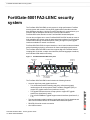
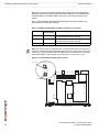
Figure 1: FortiGate-5001FA2-LENC front panel
The FortiGate-5001FA2-LENC board includes the following features:
• A total of eight front panel gigabit interfaces
• Two accelerated packet forwarding and policy enforcement gigabit
interfaces that can accept optical Small Formfactor Pluggable (SFP) or
copper SFP gigabit transceivers (interfaces 1 and 2)
• Two gigabit interfaces that can accept optical or copper SFP gigabit
transceivers (interfaces 3 and 4)
• Four 10/100/1000Base-T gigabit copper network interfaces (interfaces 5, 6,
7, 8)
• Two base backplane gigabit interfaces (port9 and port10) for HA heartbeat and
data communications across the FortiGate-5000 chassis backplane.
• DB-9 RS-232 serial console connection
• One USB connector
3 4 Optical or Copper
SFP Gigabit
1 2 Optical or Copper
SFP Gigabit
Accelerated
5 6 7 8
Gigabit Copper
Handle
Status
Module
Position
Power
USB
Flash Disk
Access
RS-232
Serial
HandleRetention
Screw
Retention
Screw
Link/Traffic

FortiGate-5001FA2-LENC Security System Guide
6 01-30000-76602-20080606
Front panel LEDs and connectors FortiGate-5001FA2-LENC security system
• Mounting hardware
• LED status indicators
The FortiGate-5001FA2-LENC board comes supplied with four optical or four
copper SFP transceivers. Before you can connect FortiGate-5001FA2-LENC
interfaces 1 to 4, you must insert the SFP transceivers into the
FortiGate-5001FA2-LENC front panel cage slots numbered 1 to 4.
The FortiGate-5001FA2-LENC board ships with two RAM DIMMs installed on the
FortiGate-5001FA2-LENC circuit board. You should confirm that the RAM DIMMs
are installed correctly before inserting the FortiGate-5001FA2-LENC board into a
chassis.
Front panel LEDs and connectors
From the FortiGate-5001FA2-LENC font panel you can view the status of the front
panel LEDs to verify that the board is functioning normally. You also connect the
FortiGate-5001FA2-LENC board to your network through the front panel ethernet
connectors. The front panel also includes the RS-232 console port for connecting
to the FortiOS CLI and a USB port. The USB port can be used with a Fortinet USB
key. For information about using the FortiUSB key, see the FortiGate-5000 Series
Firmware and FortiUSB Guide.
LEDs
Table 1 lists and describes the FortiGate-5001FA2-LENC board LEDs.
Table 1: FortiGate-5001FA2-LENC board LEDs
LED State Description
PWR Green The FortiGate-50012FA2 board is powered on.
ACC Off or
Flashing
red
The ACC LED flashes red when the
FortiGate-5001FA2-LENC board accesses the FortiOS flash
disk. The FortiOS flash disk stores the current FortiOS
firmware build and configuration files. The system accesses
the flash disk when starting up, during a firmware upgrade, or
when an administrator is using the CLI or GUI to change the
FortiOS configuration. Under normal operating conditions this
LED flashes occasionally, but is mostly off.
STA Green Normal operation.
Red The FortiGate-5001FA2-LENC is booting or a fault condition
exists.
IPM Blue The FortiGate-5001FA2-LENC is ready to be hot-swapped
(removed from the chassis). If the IPM light is blue and no
other LEDs are lit the FortiGate-5001FA2-LENC board has
lost power, possibly because of a loose or incorrectly aligned
left handle. See “Inserting a FortiGate-5001FA2-LENC board
into a chassis” on page 13 for more information.
Flashing
Blue
The FortiGate-5001FA2-LENC is changing from hot swap to
running mode or from running mode to hot swap.
Off Normal operation. The FortiGate-5001FA2-LENC board is in
contact with the chassis backplane.
1, 2, 3, 4 Green The correct cable is connected to the gigabit SFP interface.
Flashing Network activity at the gigabit SFP interface.

FortiGate-5001FA2-LENC security system Accelerated packet forwarding and policy enforcement
FortiGate-5001FA2-LENC Security System Guide
01-30000-76602-20080606 7
Connectors
Tab l e 2 lists and describes the FortiGate-5001FA2-LENC connectors.
Accelerated packet forwarding and policy enforcement
FortiGate-5001FA2-LENC Accelerated packet forwarding and policy enforcement
results in accelerated small packet performance required for voice, video, and
other multimedia streaming applications. The following traffic scenarios are
recommended for the accelerated interfaces:
• Small packet applications, such as voice over IP (VoIP).
The FortiGate-5001FA2-LENC accelerated interfaces provide wire speed
performance for small packet applications.
• Latency sensitive applications, such as multimedia.
The FortiGate-5001FA2-LENC accelerated interfaces add much less latency
than normal (non-accelerated) interfaces.
5, 6,
7, 8
Link
LED
Green The correct cable is inserted into this interface and the
connected equipment has power.
Flashing Network activity at this interface.
Speed
LED
Green The interface is connected at 1000 Mbps.
Amber The interface is connected at 100 Mbps.
Unlit The interface is connected at 10 Mbps.
Table 1: FortiGate-5001FA2-LENC board LEDs (Continued)
LED State Description
Table 2: FortiGate-5001FA2-LENC connectors
Connector Type Speed Protocol Description
1 and 2 LC SFP 1000Base-SX Ethernet Two accelerated gigabit SFP interfaces
that can accept optical or copper gigabit
transceivers. These interfaces only
operate at 1000Mbps. The accelerated
interface connectors are inverted
compared to connectors 3 and 4. See
“Installing SFP transceivers” on
page 10 for more information.
3 and 4 LC SFP 1000Base-SX Ethernet Two gigabit SFP interfaces that can
accept optical or copper gigabit
transceivers. These interfaces only
operate at 1000Mbps. See “Installing
SFP transceivers” on page 10 for more
information.
5, 6, 7, 8 RJ-45 10/100/1000
Base-T
Ethernet Copper gigabit connection to
10/100/1000Base-T copper networks.
CONSOLE DB-9 9600 bps RS-232
serial
Serial connection to the command line
interface.
USB USB FortiUSB key firmware updates and
configuration backup.

FortiGate-5001FA2-LENC Security System Guide
8 01-30000-76602-20080606
Base backplane gigabit communication FortiGate-5001FA2-LENC security system
• Session Oriented Traffic with long session lifetime, such as FTP sessions.
Packet size does not affect performance for traffic with long session lifetime.
For long sessions, processing that would otherwise be handled by the
FortiGate-5001FA2-LENC CPUs is off-loaded to the acceleration module.
• Firewall and intrusion protection (IPS), when there is a reasonable percentage
of P2P packets.
• Firewall, intrusion protection (IPS), and antivirus, when there is a reasonable
percentage of P2P packets.
• Firewall and IPSec VPN applications.
The following traffic scenarios should be handled by the normal (or non-
accelerated) FortiGate-5001FA2-LENC interfaces:
• Session oriented traffic when the session lifetime is very short.
• Firewall and antivirus only applications.
Traffic will not be off-loaded to the FortiGate-5001FA2-LENC accelerator
module. The result will be high CPU usage because of the high CPU
requirement for antivirus scanning.
FA2 interfaces and active-active HA performance
FortiOS v3.0 MR4 firmware can also use FA2 acceleration to improve
active-active HA load balancing performance. See the FortiGate HA Overview or
the FortiGate HA Guide for more information.
Base backplane gigabit communication
The FortiGate-5001FA2-LENC port9 and port10 base backplane gigabit interfaces
can be used for HA heartbeat communication between FortiGate-5001FA2-LENC
boards installed in the same or in different FortiGate-5000 chassis. You can also
configure FortiGate-5001FA2-LENC boards to use the base backplane interfaces
for data communication between FortiGate boards. To support base backplane
communications your FortiGate-5140 or 5050 chassis must include one or more
FortiSwitch-5003 boards. FortiSwitch-5003 boards are installed in chassis slots 1
and 2. The FortiGate-5020 chassis supports base backplane communication with
no additions or changes to the chassis.
For information about base backplane communication in FortiGate-5140 and
FortiGate-5050 chassis, see the FortiGate-5000 Base Backplane Communication
Guide. For information about the FortiSwitch-5003 board, see the
FortiSwitch-5003 Guide.

Hardware installation RAM DIMMs
FortiGate-5001FA2-LENC Security System Guide
01-30000-76602-20080606 9
Hardware installation
Before use, the FortiGate-5001FA2-LENC board must be correctly inserted into
an Advanced Telecommunications Computing Architecture (ACTA) chassis such
as the FortiGate-5140, FortiGate-5050, or FortiGate-5020 chassis.
Before inserting the board into a chassis you should make sure RAM DIMMS are
installed and FortiGate-5001FA2-LENC jumpers are set. SFP transceivers must
also be installed for interfaces 1 to 4 before these interfaces can be connected to
network devices.
This section describes:
• RAM DIMMs
• Installing SFP transceivers
• Changing FortiGate-5001FA2-LENC jumper settings
• Inserting a FortiGate-5001FA2-LENC board into a chassis
• Removing a FortiGate-5001FA2-LENC board from a chassis
• Troubleshooting
RAM DIMMs
The FortiGate-5001FA2-LENC board ships with two RAM DIMMs installed on the
FortiGate-5001FA2-LENC circuit board. You should confirm that the RAM DIMMs
are installed correctly before inserting the FortiGate-5001FA2-LENC board into a
chassis.
To install FortiGate-5001FA2-LENC RAM DIMMs
To complete this procedure, you need:
• A FortiGate-5001FA2-LENC board
• Two RAM DIMMs to be installed into the FortiGate-5001FA2-LENC board
RAM DIMM slots
• An electrostatic discharge (ESD) preventive wrist strap with connection cord
1 Attach the ESD wrist strap to your wrist and to an ESD socket or to a bare metal
surface on a chassis or frame.
2 Remove RAM DIMMs from their antistatic packaging.
!
Caution: FortiGate-5001FA2-LENC boards must be protected from static discharge and
physical shock. Only handle or work with FortiGate-5001FA2-LENC boards at a static-free
workstation. Always wear a grounded electrostatic discharge (ESD) preventive wrist strap
when handling FortiGate-5001FA2-LENC boards.
!
Caution: Handle DIMMs by the edges only. DIMMs are ESD-sensitive components that
can be damaged by mishandling.

FortiGate-5001FA2-LENC Security System Guide
10 01-30000-76602-20080606
Installing SFP transceivers Hardware installation
Figure 2: Location of FortiGate-5001FA2-LENC RAM DIMM slots
3 Insert each RAM DIMM perpendicular to the RAM DIMM slots. Push the DIMM
firmly into place using the minimum amount of force required. When the DIMM is
properly seated, the socket guide posts click into place.
Do not use excessive force when installing a DIMM.
The RAM slots allow only one alignment of each RAM DIM. If you cannot lock the
locking levers the DIM is not aligned correctly or is in upside-down.
Installing SFP transceivers
The FortiGate-5001FA2-LENC board ships with four SFP transceivers that you
must install for normal operation of the FortiGate-5001FA2-LENC board. The SFP
transceivers are inserted into cage sockets numbered 1 to 4 on the
FortiGate-5001FA2-LENC front panel. You can install the SFP transceivers before
or after inserting the FortiGate-5001FA2-LENC board into a FortiGate chassis.
JP3
JP2
JP1
RAM DIMM
slots
Front Faceplate
Note: Cage slots 1 and 2 are rotated 180 degrees. Install the transceivers in slots 1 and 2
inverted compared to the orientation of the transceivers in slots 3 and 4.

Hardware installation Changing FortiGate-5001FA2-LENC jumper settings
FortiGate-5001FA2-LENC Security System Guide
01-30000-76602-20080606 11
You can install the following types of SFP transceivers for connectors 1, 2, 3,
and 4:
• optical SFP transceivers
• SFP 1000Base-LX, SM module
• SFP 1000Base-SX, MM module (multimode)
• copper SFP transceivers
• SFP 1000Base-T, SERDES version only (SGMII version not supported)
To install SFP transceivers
To complete this procedure, you need:
• A FortiGate-5001FA2-LENC board
• Four SFP transceivers
• An electrostatic discharge (ESD) preventive wrist strap with connection cord
1 Attach the ESD wrist strap to your wrist and to an ESD socket or to a bare metal
surface on the chassis or frame.
2 Remove the caps from SFP cage sockets on the FortiGate-5001FA2-LENC front
panel.
3 For cage slots 1 and 2, hold the sides of the SFP transceiver and slide SFP
transceiver into the cage socket until it clicks into place.
4 For cage slots 3 to 8, turn each SFP transceiver over before sliding it into the cage
slot until it locks into place.
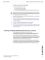
Changing FortiGate-5001FA2-LENC jumper settings
The JP3 jumper on the FortiGate-5001FA2-LENC board is factory set by Fortinet
into one of two positions (see Figure 3 on page 12):
• For a FortiGate-5140 or FortiGate-5050 chassis, the jumper connects pins 2
and 3
• For a FortiGate-5020 chassis, the jumper connects pins 1 and 2
The jumper must connect pins 2 and 3 if the chassis contains a shelf manager.
Both the FortiGate-5140 and the FortiGate-5050 contain shelf managers, and the
FortiGate-5020 does not.
If the JP3 jumper settings are incorrect, when you insert the
FortiGate-5001FA2-LENC board into a chassis the board may not start up or may
not be able to communicate with the chassis shelf manager.
!
Caution: FortiGate-5001FA2-LENC boards must be protected from static discharge and
physical shock. Only handle or work with FortiGate-5001FA2-LENC boards at a static-free
workstation. Always wear a grounded electrostatic discharge (ESD) preventive wrist strap
when handling FortiGate-5001FA2-LENC boards.
!
Caution: Handling the SFP transceivers by holding the release Latch can damage the
connector. Do not force the SFP transceivers into the cage slots. If the transceiver does not
easily slide in and click into place, it may not be aligned correctly. If this happens, remove
the SFP transceiver, realign it and slide it in again.

FortiGate-5001FA2-LENC Security System Guide
12 01-30000-76602-20080606
Changing FortiGate-5001FA2-LENC jumper settings Hardware installation
Normally, because the jumpers are factory set, you do not have to change them.
However, if you are moving a FortiGate-5001FA2-LENC from a FortiGate-5140 or
FortiGate-5050 to a FortiGate-5020 or the reverse, you need to move the JP3
jumper.
Also, if a new FortiGate-5001FA2-LENC board does not function properly, you
should check the JP3 jumper settings.
Figure 3: FortiGate-5001FA2-LENC jumper settings
Table 3: FortiGate-5001FA2-LENC JP3 jumper settings for each chassis
Chassis Correct JP3
Jumper Setting
Result of wrong jumper setting
FortiGate-5140 pins 2 and 3 Shelf manager cannot find FortiGate-5001FA2-LENC
board. No chassis information available.
FortiGate-5050 pins 2 and 3 Shelf manager cannot find FortiGate-5001FA2-LENC
board. No chassis information available.
FortiGate-5020 pins 1 and 2 FortiGate-5001FA2-LENC board will not start up.
Note: If the shelf manager in a FortiGate-5140 or FortiGate-5050 chassis is missing or not
functioning, FortiGate-5001FA2-LENC boards with JP3 jumper connecting pins 2 and 3 will
not start up. To operate FortiGate-5001FA2-LENC boards in a FortiGate-5140 or FortiGate-
5050 chassis without a shelf manager, set the JP3 jumper to connect pins 1 and 2.
JP3
JP2
JP1
Front Faceplate
5050 and 5140 chassis
5020 chassis
Pins 2 and 3
Pins 1 and 2
JP3
JP3

Hardware installation Inserting a FortiGate-5001FA2-LENC board into a chassis
FortiGate-5001FA2-LENC Security System Guide
01-30000-76602-20080606 13
To change or verify the JP3 jumper setting
To complete this procedure, you need:
• A FortiGate-5001FA2-LENC board
• A tool for moving jumpers (optional)
• An electrostatic discharge (ESD) preventive wrist strap with connection cord
1 Attach the ESD wrist strap to your wrist and to an ESD socket or to a bare metal
surface on a chassis or frame.
2 If you have installed the FortiGate-5001FA2-LENC board in a chassis, remove it.
For removal instructions, see “Removing a FortiGate-5001FA2-LENC board from
a chassis” on page 17.
3 Use Figure 3 to locate the jumper settings on the circuit board.
4 If required, carefully move the jumper to the correct setting.
5 You can now insert the board into a chassis and verify that it is operating correctly.
For inserting instructions, see “Inserting a FortiGate-5001FA2-LENC board into a
chassis” on page 13.
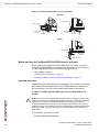
Inserting a FortiGate-5001FA2-LENC board into a chassis
The following procedure describes how to correctly use the
FortiGate-5001FA2-LENC mounting components shown in Figure 4 to insert a
FortiGate-5001FA2-LENC board into a FortiGate-5000 series chassis slot.
The FortiGate-5001FA2-LENC board left handle contacts to a hidden power
switch. The board must be fully installed in a chassis slot and this handle must be
closed and locked for the FortiGate-5001FA2-LENC board to receive power and
operate normally. If the FortiGate-5001FA2-LENC board is not receiving power,
the IPM LED glows blue and all other LEDs remain off.
It is important to carefully seat the FortiGate-5001FA2-LENC board all the way
into the chassis, to not use too much force on the handles, and to make sure that
the handles are properly locked and engaged with the hidden power switch. Only
then will the FortiGate-5001FA2-LENC board power-on and start up correctly.
!
Caution: FortiGate-5001FA2-LENC boards must be protected from static discharge and
physical shock. Only handle or work with FortiGate-5001FA2-LENC boards at a static-free
workstation. Always wear a grounded electrostatic discharge (ESD) preventive wrist strap
when handling FortiGate-5001FA2-LENC boards.

FortiGate-5001FA2-LENC Security System Guide
14 01-30000-76602-20080606
Inserting a FortiGate-5001FA2-LENC board into a chassis Hardware installation
Figure 4: FortiGate-5001FA2-LENC mounting components
Before inserting the FortiGate-5001FA2-LENC board in a chassis
Before installing the FortiGate-5001FA2-LENC board in a chassis you should
verify that the RAM DIMMs are installed and the JP3 jumper is set correctly. You
can also install the SFP transceivers before inserting the board.
• “RAM DIMMs” on page 9
• “Installing SFP transceivers” on page 10
• “Changing FortiGate-5001FA2-LENC jumper settings” on page 11
Insertion procedure
FortiGate-5001FA2-LENC boards are hot swappable. The procedure for inserting
the FortiGate-5001FA2-LENC board into a FortiGate-5000 series chassis slot is
the same whether or not the FortiGate-5000 series chassis is powered on.
To insert a FortiGate-5001FA2-LENC board into a FortiGate-5000 series
chassis
To complete this procedure, you need:
• A FortiGate-5001FA2-LENC board
Closed
Open
Alignment Pin
Retention
Screw
Lock
Handle
Alignment Pin
Retention
Screw
Lock
Handle
Switch Contact
Power
Switch
Lock
Left Handle
!
Caution: Do not carry the FortiGate-5001FA2-LENC board by holding the handles. When
inserting or removing the FortiGate-5001FA2-LENC board from a chassis slot, handle the
board by the front panel. The handles are designed for positioning and locking the
FortiGate-5001FA2-LENC board into a slot in a chassis only and should not be used for
handling the board. If the handles become bent or damaged the FortiGate-5001FA2-LENC
board may not align correctly in the chassis slot and the handles may not activate the
power switch.

Hardware installation Inserting a FortiGate-5001FA2-LENC board into a chassis
FortiGate-5001FA2-LENC Security System Guide
01-30000-76602-20080606 15
• A FortiGate-5000 series chassis with an empty slot
• An electrostatic discharge (ESD) preventive wrist strap with connection cord
1 Attach the ESD wrist strap to your wrist and to an ESD socket or to a bare metal
surface on the chassis or frame.
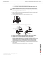
2 Unlock the left and right handles by squeezing the handle locks.
3 Open the left and right handles to their fully open positions.
4 Insert the FortiGate-5001FA2-LENC board into the empty slot in the chassis.
5 Carefully guide the board into the chassis using the rails in the slot.
Insert the board by applying moderate force to the front faceplate (not the
handles) to slide the board into the slot. The board should glide smoothly into the
chassis. If you encounter any resistance while sliding the board in, the board
could be aligned incorrectly. Pull the board back out and try inserting it again.
6 Slide the board in until the alignment pins are inserted half way into their sockets
in the chassis.
If the chassis is powered on the IPM LED lights up and turns blue.
!
Caution: FortiGate-5001FA2-LENC boards must be protected from static discharge and
physical shock. Only handle or work with FortiGate-5001FA2-LENC boards at a static-free
workstation. Always wear a grounded electrostatic discharge (ESD) preventive wrist strap
when handling FortiGate-5001FA2-LENC boards.
Unlock
Handle
Open
Fully Open
Alignment Pin
Handle
Handle

FortiGate-5001FA2-LENC Security System Guide
16 01-30000-76602-20080606
Inserting a FortiGate-5001FA2-LENC board into a chassis Hardware installation
7 Turn both handles to their fully-closed positions.
The handles should hook into the sides of the chassis slot. Closing the handles
draws the FortiGate-5001FA2-LENC board into place in the chassis slot and into
contact with the chassis backplane. The FortiGate-5001FA2-LENC front panel
should be in contact with the chassis front panel. When the handles are fully-
closed they lock into place.
If the chassis is powered on, as the board slides into place the IPM LED starts
flashing blue.
8 Fully tighten the left and right retention screws to lock the
FortiGate-5001FA2-LENC board into position in the chassis slot.
.
If the chassis is powered on the PWR LED turns green and the STA LED turns
red. The ACC LED also starts flashing red. After a few minutes, if the board is
operating correctly the front panel LEDs are lit as described in Tab le 4 .
Close
Fully Closed
and Locked
Alignment Pin
Alignment Pin
Handle
Table 4: FortiGate-5001FA2-LENC normal operating LEDs
LED State
PWR Green
ACC Off (Or flashing red when the system accesses the flash disk.)
STA Green
IPM Off
Tighten
Retention
Screw

Hardware installation Removing a FortiGate-5001FA2-LENC board from a chassis
FortiGate-5001FA2-LENC Security System Guide
01-30000-76602-20080606 17
Removing a FortiGate-5001FA2-LENC board from a chassis
The following procedure describes how to correctly use the
FortiGate-5001FA2-LENC mounting components shown in Figure 4 to remove a
FortiGate-5001FA2-LENC board from a FortiGate-5000 series chassis slot.
To remove a FortiGate-5001FA2-LENC board from a FortiGate-5000 series
chassis
FortiGate-5001FA2-LENC boards are hot swappable. The procedure for removing
the FortiGate-5001FA2-LENC board from a FortiGate-5000 series chassis slot is
the same whether or not the FortiGate-5000 series chassis is powered on.
To complete this procedure, you need:
• A FortiGate-5000 series chassis with a FortiGate-5001FA2-LENC board
installed
• An electrostatic discharge (ESD) preventive wrist strap with connection cord
1 Attach the ESD wrist strap to your wrist and to an ESD socket or to a bare metal
surface on the chassis or frame.
2 Disconnect all cables from the FortiGate-5001FA2-LENC board, including all
network cables, the console cable, and any USB cables or keys.
3 Fully loosen the retention screws on the left and right sides of the
FortiGate-5001FA2-LENC front panel.
4 Unlock the left and right handles by squeezing the handle locks.
!
Caution: Do not carry the FortiGate-5001FA2-LENC board by holding the handles. When
inserting or removing the FortiGate-5001FA2-LENC board from a chassis slot, handle the
board by the front panel. The handles are designed for positioning and locking the
FortiGate-5001FA2-LENC board into a slot in a chassis only and should not be used for
handling the board. If the handles become bent or damaged the FortiGate-5001FA2-LENC
board may not align correctly in the chassis slot and the left handle may not activate the
power switch.
!
Caution: FortiGate-5001FA2-LENC boards must be protected from static discharge and
physical shock. Only handle or work with FortiGate-5001FA2-LENC boards at a static-free
workstation. Always wear a grounded electrostatic discharge (ESD) preventive wrist strap
when handling FortiGate-5000 series or FortiSwitch-5000 series boards.
Loosen
Retention
Screw

FortiGate-5001FA2-LENC Security System Guide
18 01-30000-76602-20080606
Troubleshooting Hardware installation
5 Open the left and right handles to their fully open positions.
Opening the handles slides the board a short distance out of the slot,
disconnecting the board from the chassis backplane.
The IPM LED turns blue. All other LEDs turn off.
6 Pull the board about half way out.
All LEDs turn off.
7 Turn both handles to their fully-closed positions.
When the handles are fully-closed they lock into place.
8 Carefully slide the board completely out of the slot.
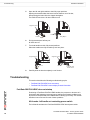
Troubleshooting
This section describes the following troubleshooting topics:
• FortiGate-5001FA2-LENC does not startup
• FortiGate-5001FA2-LENC cannot display chassis information
FortiGate-5001FA2-LENC does not startup
Positioning of FortiGate-5001FA2-LENC handles, the presence or absence of a
functioning shelf manager, incorrect jumper settings and firmware problems may
all prevent a FortiGate-5001FA2-LENC board for starting up correctly. This section
describes how to find and fix each of these problems.
All chassis: left handle not contacting power switch
The left handle activates the FortiGate-5001FA2-LENC board power switch.
Open
Fully Open
Alignment Pin
Handle
Handle
Close
Fully Closed
and Locked
Alignment Pin
Alignment Pin
Handle

Hardware installation Troubleshooting
FortiGate-5001FA2-LENC Security System Guide
01-30000-76602-20080606 19
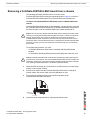
Figure 5: Location of FortiGate-5001FA2-LENC power switch
If the left handle is damaged or positioned incorrectly the
FortiGate-5001FA2-LENC board does not receive power and will not start up.
Make sure the left handle is correctly aligned, fully inserted and locked.
Sometimes you may have to make small adjustments to the handle to achieve
contact with the switch.
FortiGate-5020 chassis: incorrect FortiGate-5001FA2-LENC
jumper settings
If the JP3 jumper on the FortiGate-5001FA2-LENC circuit board is set to detect a
shelf manager, the FortiGate-5001FA2-LENC board will not start up when inserted
into a FortiGate-5020 chassis. This occurs because the FortiGate-5020 chassis
does not have a shelf manager.
To fix the problem, remove the FortiGate-5001FA2-LENC board and check the
position of the JP3 jumper (see Figure 3 on page 12). Make sure the jumper
connects pins 1 and 2 (to the right when seen from the front of the board).
FortiGate-5140 or 5050 chassis: shelf manager not installed or
not functioning
If you are operating a FortiGate-5001FA2-LENC in a FortiGate-5140 or 5050
chassis, the FortiGate-5001FA2-LENC board will not start up if the JP3 jumper
connects pins 2 and 3 (see Figure 3 on page 12) and a shelf manager is not
installed or is not operating correctly.
If the shelf manager is not installed or not operating correctly, when you insert a
FortiGate-5001FA2-LENC board, the board attempts to communicate with the
shelf manager. If the FortiGate-5001FA2-LENC board cannot communicate with
the shelf manager, the board will not startup.
If a shelf manager is installed, make sure it is functioning normally (the Status LED
is green and all other LEDs are off). If the shelf manager is not functioning
normally, you can try removing it from the chassis and reinstalling it. If this does
not solve the problem, contact Fortinet Technical Support.
If the shelf manager has been removed from the chassis, you should re-install it. If
you are planning on operating the chassis without a shelf manager, you can move
the FortiGate-5001FA2-LENC JP3 jumper between pins 1 and 2. The
FortiGate-5001FA2-LENC should now start up.
Switch Contact
Power
Switch
Lock
Left Handle

FortiGate-5001FA2-LENC Security System Guide
20 01-30000-76602-20080606
Troubleshooting Hardware installation
All chassis: Firmware problem
If the FortiGate-5001FA2-LENC board power switch is connected and the JP3
jumper and shelf manager are set as required, and the FortiGate-5001FA2-LENC
still does not start up, the problem could be with FortiOS. Connect to the
FortiGate-5001FA2-LENC console and try cycling the power to the board. If the
BIOS starts up, interrupt the BIOS startup and install a new firmware image. For
details about installing a new firmware image in this way, see the FortiGate-5000
Series Firmware and FortiUSB Guide.
If this does not solve the problem, contact Fortinet Technical Support.
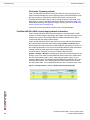
FortiGate-5001FA2-LENC cannot display chassis information
If the FortiGate-5001FA2-LENC board is installed in a FortiGate-5140 or 5050
chassis, if a shelf manager is operating in the chassis, and if the JP3 jumper is set
between pins 2 and 3, the FortiGate-5001FA2-LENC board should be able to
communicate with the chassis shelf manager.
If the FortiGate-5001FA2-LENC board can communicate with the shelf manager,
the FortiGate-5001FA2-LENC web-based manager System > Chassis pages
should display information about the boards installed in the chassis. If any one of
the conditions listed above are not met, theFortiGate-5001FA2-LENC web-based
manager system chassis pages will not display chassis information.
If all of the above conditions are met, the FortiGate-5001FA2-LENC
System > Chassis > Blades list displays a list of all of the boards installed in the
chassis. If any of the other FortiGate-5001FA2-LENC boards in the chassis have
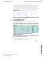
the JP3 jumper between pins 1 and 2, these slots will appear empty. Figure 6
shows the blades list for a FortiGate-5001FA2-LENC board installed in slot 3 of a
FortiGate-5050 chassis. The FortiGate-5001FA2-LENC boards in slots 3 and 4
are called node cards. The FortiGate-5003 board in slot 2 is called a switch card.
Figure 6: Example System > Chassis > Blades web-based manager page
Page is loading ...
Page is loading ...
Page is loading ...
Page is loading ...
Page is loading ...
Page is loading ...
Page is loading ...
Page is loading ...
Page is loading ...
Page is loading ...
Page is loading ...
Page is loading ...
Page is loading ...
Page is loading ...
-
 1
1
-
 2
2
-
 3
3
-
 4
4
-
 5
5
-
 6
6
-
 7
7
-
 8
8
-
 9
9
-
 10
10
-
 11
11
-
 12
12
-
 13
13
-
 14
14
-
 15
15
-
 16
16
-
 17
17
-
 18
18
-
 19
19
-
 20
20
-
 21
21
-
 22
22
-
 23
23
-
 24
24
-
 25
25
-
 26
26
-
 27
27
-
 28
28
-
 29
29
-
 30
30
-
 31
31
-
 32
32
-
 33
33
-
 34
34


Fortinet 5001FA2-LENC User manual
- Category
- Networking
- Type
- User manual
- This manual is also suitable for
Ask a question and I''ll find the answer in the document
Finding information in a document is now easier with AI
Related papers
-
Fortinet 3600 User manual
-
-
-
-
-
-
-
-
-
Other documents
-
Tripp Lite 1U-24 Port Feed-Through Patch Panel Installation guide
-
RACKMOUNTH FORTIRACK RM-FR-T14, RM-FR-T14i Rackmount User manual
-
3com 78-7072-01 User manual
-
Artesyn ATCA-8310 Quick start guide
-
Emerson 72EE) Installation guide
-
-
-
-
-
BEA 10PBS45X User manual