Page is loading ...

1
Quadra-Fire • QV-PIER, QV-ST Series: HV-IPI • 2005-901 Rev. G • 2/06
Models:
QV-Pier
QV-ST
Series: HV-IPI
Owner’s Manual
Installation and Operation
DO NOT DISCARD THIS MANUAL
CAUTION
Important operating
and maintenance
instructions included.
•• •
DO NODO NO
DO NODO NO
DO NO
TT
TT
T
DISCARDDISCARD
DISCARDDISCARD
DISCARD
Read, understand and follow
these instructions for safe
installation and operation.
Leave this manual with
party responsible for
use and operation.
• Do not store or use gasoline or other flam-
mable vapors and liquids in the vicinity of this
or any other appliance.
• What to do if you smell gas
- Do not try to light any appliance
- Do not touch any electrical switch. Do not
use any phone in your building.
- Immediately call your gas supplier from a
neighbor’s phone. Follow the gas suppli-
er’s instructions.
- If you cannot reach your gas supplier, call
the fire department.
• Installation and service must be performed by
a qualified installer, service agency, or the gas
supplier.
In the Commonwealth of Massachusetts:
• installation must be performed by a licensed plumber
or gas fitter;
• a CO detector shall be installed in the room where the
appliance is installed.
WARNING: If the information in these
instructions is not followed exactly, a fire
or explosion may result causing prop-
erty damage, personal injury, or death.
Please contact your Quadra-Fire dealer with any questions
or concerns. For the number of your nearest Quadra-Fire dealer,
please call 1-800-926-4356.
Quadra-Fire, a brand of Hearth & Home Technologies Inc.
1445 North Highway, Colville, WA 99114
Î
WARNING: IMPROPER INSTALLATION,
ADJUSTMENT, ALTERATION, SERVICE OR
MAINTENANCE CAN CAUSE INJURY OR
PROPERTY DAMAGE. REFER TO THIS
MANUAL. FOR ASSISTANCE OR ADDITION-
AL INFORMATION CONSULT A QUALIFIED
INSTALLER, SERVICE AGENCY, OR THE
GAS SUPPLIER.
This appliance may be installed in an aftermarket,
permanently located, manufactured (mobile) home,
where not prohibited by local codes.
This appliance is only for use with the type of gas
indicated on the rating plate. This appliance is not
convertible for use with other gases, unless a certi-
fied kit is used.
Printed in U.S.A.
Copyright 2006
This product may be covered by one or more of the following patents: (United States) 4593510, 4686807, 4766876, 4793322, 4811534, 5000162, 5016609, 5076254, 5113843, 5191877, 5218953, 5263471, 5328356,
5341794, 5347983, 5429495, 5452708, 5542407, 5601073, 5613487, 5647340, 5688568, 5762062, 5775408, 5890485, 5931661, 5941237, 5947112, 5996575, 6006743, 6019099, 6048195, 6053165, 6145502, 6170481,
6237588, 6296474, 6374822, 6413079, 6439226, 6484712, 6543698, 6550687, 6601579, 6672860, 6688302B2, 6715724B2, 6729551, 6736133, 6748940, 6748942, 6769426, 6774802, 6796302, 6840261, 6848441,
6863064, 6866205, 6869278, 6875012, 6880275, 6908039, 6919884, D320652, D445174, D462436; (Canada) 1297749, 2195264, 2225408, 2313972; (Australia) 780250, 780403, 1418504 or other U.S. and foreign
patents pending.

2
Quadra-Fire • QV-PIER, QV-ST Series: HV-IPI • 2005-901 Rev. G • 2/06
These units MUST use one of the vent systems
described in the Installing the Fireplace section of
the Installers Guide. NO OTHER vent systems or
components MAY BE USED.
This gas fireplace and vent assembly MUST be
vented directly to the outside and MUST NEVER be
attached to a chimney serving a separate solid fuel
burning appliance. Each gas appliance MUST USE
a separate vent system. Common vent systems are
PROHIBITED.
INSPECT the external vent cap on a regular basis to
make sure that no debris is interfering with the air
flow.
The glass door assembly MUST be in place and
sealed, and the trim door assembly MUST be in
place on the fireplace before the unit can be placed
into safe operation.
DO NOT OPERATE this appliance with the glass
door removed, cracked, or broken. Replacement of
the glass door should be performed by a licensed
or qualified service person. DO NOT strike or slam
the glass door.
The glass door assembly SHALL ONLY be
replaced as a complete unit, as supplied by the gas
fireplace manufacturer. NO SUBSTITUTE material
may be used.
DO NOT USE abrasive cleaners on the glass door
assembly. DO NOT ATTEMPT to clean the glass
door when it is hot.
Turn off the gas before servicing this appliance. It is
recommended that a qualified service technician
perform an appliance check-up at the beginning of
each heating season.
Any safety screen or guard removed for servicing
must be replaced before operating this appliance.
DO NOT place furniture or any other combustible
household objects within 36 inches of the fireplace
front.
READ and UNDERSTAND all instructions carefully
before starting the installation. FAILURE TO
FOLLOW these installation instructions may result
in a possible fire hazard and will void the warranty.
Prior to the first firing of the fireplace, READ the
Using Your Fireplace section of the Owners Guide.
DO NOT USE this appliance if any part has been
under water. Immediately CALL a qualified service
technician to inspect the unit and to replace any part
of the control system and any gas control which has
been under water.
THIS UNIT IS NOT FOR USE WITH SOLID FUEL.
Installation and repair should be PERFORMED by a
qualified service person. The appliance and venting
system should be INSPECTED before initial use
and at least annually by a professional service
person. More frequent cleaning may be required
due to excessive lint from carpeting, bedding
material, etc. It is IMPERATIVE that the unit’s
control compartment, burners, and circulating air
passageways
BE KEPT CLEAN to provide for
adequate combustion and ventilation air.
Always KEEP the appliance clear and free from
combustible materials, gasoline, and other
flammable vapors and liquids.
NEVER OBSTRUCT the flow of combustion and
ventilation air. Keep the front of the appliance
CLEAR of all obstacles and materials for servicing
and proper operations.
Due to the high temperature, the appliance should
be LOCATED out of traffic areas and away from
furniture and draperies. Clothing or flammable
material SHOULD NOT BE PLACED on or near the
appliance.
Children and adults should be ALERTED to the
hazards of high surface temperature and should
STAY AWAY to avoid burns or clothing ignition.
Young children should be CAREFULLY SUPERVISED
when they are in the same room as the appliance.
!
!
!
!
!
!
!
!
!
!
!
!
!
!
!
!
!
Safety and Warning Information
!
!

3
Quadra-Fire • QV-PIER, QV-ST Series: HV-IPI • 2005-901 Rev. G • 2/06
Table of Contents
Safety and Warning Information.................................................. 2
Service Parts List ......................................................................... 4
Approvals and Codes .................................................................. 9
Appliance Certification ................................................................................... 9
Installation Codes .......................................................................................... 9
Getting Started............................................................................ 10
Introducing the Quadra-Fire Gas Fireplaces ................................................. 10
Pre-install Preparation ................................................................................. 10
Installing the Fireplace ...............................................................13
Step 1. Locating the Fireplace .................................................................... 13
Step 2. Framing the Fireplace ..................................................................... 14
Step 3. Installing the Vent System .............................................................. 17
A. Vent System Approvals ......................................................... 17
B. Installing Vent Components ................................................... 24
C. Vent Termination.................................................................... 26
Step 4. Positioning, Leveling, and Securing the Fireplace ........................... 29
Step 5. The Gas Control System ................................................................ 29
Step 6. The Gas Supply Line ...................................................................... 30
Step 7. Gas Pressure Requirements........................................................... 30
Step 8. Wiring the Fireplace........................................................................ 31
Step 9. Finishing......................................................................................... 33
Step 10. Installing Trim, Logs & Ember Material........................................... 34
Installing the Trim........................................................................ 34
Positioning the Logs ................................................................... 34
Shutter Settings .......................................................................... 34
Glass Specifications ................................................................... 34
Preparing Electric Ember Bed and Lava Rock ............................. 34
Placing the Ember Material ......................................................... 36
Ember Light Replacement ........................................................... 37
Step 11. Before Lighting the Fireplace........................................................ 37
Step 12. Lighting the Fireplace ................................................................... 37
After the Installation..................................................................................... 37
Maintaining and Servicing Your Fireplace................................38
Troubleshooting ......................................................................... 39
Warranty ...................................................................................... 41
Î
Î
Î = Contains updated information.
Î

4
Quadra-Fire • QV-PIER, QV-ST Series: HV-IPI • 2005-901 Rev. G • 2/06
Part number list on following page.
6 Log Assembly
(NG, LP) Exploded Parts Diagram
Service Parts List
QV-Pier-HV-IPI
Beginning Manufacturing Date: 6-03
Ending Manufacturing Date: ______
7
8
10
11
12
7
9
13
5
2
1
3
4

5
Quadra-Fire • QV-PIER, QV-ST Series: HV-IPI • 2005-901 Rev. G • 2/06
SERVICE PARTS LIST
IMPORTANT: THIS IS DATED INFORMATION. The most current information is located on your dealers VIP site. When ordering,
supply serial and model numbers to ensure correct service parts.
ITEM COMMON PART SERIAL # PART NUMBER
Burner Orifice NG (#33DMS) 582-833
Burner Orifice LP (#50DMS) 582-850
1 End Glass Assembly GLA-MS
2 Glass Door Assembly GLA-6TROC
3 Burner Assembly 2005-006
4Log Grate 2005-012
5 Side Refractory SRV2005-730
6 Log Set Assembly LOGS-MSR
7Log 1 SRV2005-701
8Log 2 SRV2005-700
9Log 3 SRV2005-702
10 Log 4 SRV2005-703
11 Log 5 SRV2005-704
12 Log 6 SRV2005-705
13 Log 7 SRV703-703
Andirons 80784
Lava Rock Bag 2005-790
Flue Restrictor 385-128
Teco-Sil, 5 lb. bag 700-790
Mineral Wool 050-721
Fiberglass Rope 060-455
Bracket, Andiron 2005-149
Kapton, Lens 2005-165
Glass Latch Support Assembly 386-122A
Insullation Board (side) 2006-136
Insullation Board (end) 2006-137
Ember Mesh Assembly 2006-008
Junction Box 4021-013
3V Plug 593-593A
Conversion Kit NG NGK-MS
Conversion Kit LP LPK-MS
Pilot Tube SRV485-301
Battery Pack 593-594A
ACCESSORIES
Fan Kit GFK-160A
Remote Control Kit RC-SMART-HNG
Remote Control Kit SMART-STAT-HNG
Remote Control - Multi-functional RCT-MLT-HNG
Wall Switch, Multi-functional WSK-MLT
Plug Adapator Kit (for WSK-MLT PLUG-ADP
QV-PIER-HV-IPI
Í
Í
Í
Í
Í
Í
Í

6
Quadra-Fire • QV-PIER, QV-ST Series: HV-IPI • 2005-901 Rev. G • 2/06
(NG, LP) Exploded Parts Diagram
Service Parts
QV-ST-HV-IPI
Beginning Manufacturing Date: 6-03
Ending Manufacturing Date: ______
Part number list on following page.
5 Log Assembly
6
7
9
10
11
7
8
12
4
2
3
1

7
Quadra-Fire • QV-PIER, QV-ST Series: HV-IPI • 2005-901 Rev. G • 2/06
SERVICE PARTS LIST
IMPORTANT: THIS IS DATED INFORMATION. The most current information is located on your dealers VIP site. When ordering,
supply serial and model numbers to ensure correct service parts.
QV-ST-HV-IPI
ITEM COMMON PART SERIAL # PART NUMBER
Burner Orifice NG (#32DMS) 582-832
Burner Orifice LP (#50DMS) 582-850
1 Glass Door Assembly GLA-6TROC
2 Burner Assembly 2005-006
3Log Grate 2005-012
4Side Refractory SRV2005-730
5 Log Set Assembly LOGS-MSR
6Log 1 SRV2005-701
7Log 2 SRV2005-700
8Log 3 SRV2005-702
9 Log 4 SRV2005-703
10 Log 5 SRV2005-704
11 Log 6 SRV2005-705
12 Log 7 SRV703-703
Andirons 80784
Lava Rock Bag 2005-790
Flue Restrictor 385-128
Teco-Sil, 5 lb. bag 700-790
Hood, Black SRV60-143-BK
Glass Latch Support Assembly 386-122A
Mineral Wool 050-721
Fiberglass Rope 060-455
Bracket, Andiron 2005-149
Kapton, Lens 2005-165
Non-Combustible board 2005-172
Ember Mesh Assembly 2005-008
Junction Box 4021-013
3V Plug 593-593A
Conversion Kit NG NGK-MS
Conversion Kit LP LPK-MS
Pilot Tube SRV485-301
Battery Pack 593-594A
ACCESSORIES
Fan Kit GFK-160A
Remote Control Kit RC-SMART-HNG
Remote Control Kit SMART-STAT-HNG
Remote Control - Multi-functional RCT-MLT-HNG
Wall Switch, Multi-functional WSK-MLT
Plug Adapator Kit (for WSK-ML PLUG-ADP
Í
Í
Í
Í
Í
Í
Í
Í

8
Quadra-Fire • QV-PIER, QV-ST Series: HV-IPI • 2005-901 Rev. G • 2/06
(NG, LP) Exploded Parts Diagram
Service Parts
Beginning Manufacturing Date: 6-03
Ending Manufacturing Date: ______
QV-PIER-HV-IPI
QV-ST-HV-IPI
Î
Î
ITEM DESCRIPTION SERIAL # PART NUMBER
1 ON/OFF Rocker Switch 060-511
2 ON/OFF Wire Assembly 060-521A
3Valve NG 750-500
3Valve LP 750-501
4 Flexible Gas Connector 2005-009
5 Module 593-592
6 Wire Assembly 593-590A
7 Ember Box Assembly 2005-114
8Pilot Assembly NG 385-510A
8Pilot Assembly LP 385-511A
9 Pilot Bracket 2005-118
10 Gasket Orifice 2005-166
11 Valve Bracket 2005-120
12 Flex Ball Valve Assembly 302-320A
13 Pilot Assembly Support 385-120
14 Ground Strap 385-512
Regulator, NG NGK-DXV
Regulator, LP LPK-DXV
Pilot Tube 446-301
Orifice Spud NG 446-505
Orifice Spud LP 446-517
NOTE: Replacement bulbs to be supplied by homeowner. Recommended replacements: Sylvania Mini Candelabra 75 watts.
1
2
4
5
6
7
8
9
10
3
11
12
14
13
Í
Í

9
Quadra-Fire • QV-PIER, QV-ST Series: HV-IPI • 2005-901 Rev. G • 2/06
Appliance Certification
The Quadra-Fire fireplace models discussed in this Installers
Guide have been tested to certification standards and listed
by the applicable laboratories.
Certification
MODELS: QV-PIER-HV-IPI, QV-ST-HV-IPI
LABORATORY: Underwriters Laboratories
TYPE: Vented Gas Fireplace Heater
STANDARD: ANSI Z21.88•CGA2.22•UL307B
Installation Codes
The fireplace installation must conform to local codes. Before
installing the fireplace, consult the local building code
agency to ensure that you are in compliance with all
applicable codes, including permits and inspections.
In the absence of local codes, the fireplace installation must
conform to the National Fuel Gas Code ANSI Z223.1 (in the
United States) or the CAN/CGA-B149 Installation Codes
(in Canada). The appliance must be electrically grounded
in accordance with local codes or, in the absence of local
codes with the National Electric Code ANSI/NFPA No. 70
(in the United States), or to the CSA C22.1 Canadian Electric
Code (in Canada).
These models may be installed in a bedroom or bed-sitting
room in the U.S.A. and Canada.
1
Approvals and
Codes
High Altitude Installations
U.L. Listed gas appliances are tested and approved with-
out requiring changes for elevations from 0 to 2,000 feet in
the U. S. A. and in Canada.
When installing this appliance at an elevation above 2,000
feet, it may be necessary to decrease the input rating by
changing the existing burner orifice to a smaller size. Input
rate should be reduced by 4% for each 1000 feet above a
2000 foot elevation in the U.S.A. or 10% for elevations
between 2000 and 4500 feet in Canada. If the heating value
of the gas has been reduced, these rules do not apply. To
identify the proper orifice size, check with the local gas
utility.
If installing this appliance at an elevation above 4,500 feet
(in Canada), check with local authorities.

10
Quadra-Fire • QV-PIER, QV-ST Series: HV-IPI • 2005-901 Rev. G • 2/06
2
Getting Started
Introducing the Quadra-Fire Gas Fireplaces
Quadra-Fire direct vent gas fireplaces are designed to op-
erate with all combustion air siphoned from outside of the
building and all exhaust gases expelled to the outside.
The information contained in this Installers Guide, unless
noted otherwise, applies to all models and gas control
systems. Gas fireplace diagrams, including the dimensions,
are shown in this section.
Pre-install Preparation
This gas fireplace and its components are tested and safe
when installed in accordance with this Installers Guide.
Report to your dealer any parts damaged in shipment,
particularly the condition of the glass. Do not install any
unit with damaged, incomplete, or substitute parts.
The vent system components are shipped in separate pack-
ages. The gas logs are packaged separately and must be
field installed.
Read all of the instructions before starting the instal-
lation. Follow these instructions carefully during the
installation to ensure maximum safety and benefit.
Failure to follow these instructions will void the own-
er’s warranty and may present a fire hazard.
The Quadra-Fire Warranty will be voided by, and Quadra-
Fire disclaims any responsibility for, the following actions:
• Installation of any damaged fireplace or vent system
component.
• Modification of the fireplace or direct vent system.
• Installation other than as instructed by Quadra-Fire.
• Improper positioning of the gas logs or the glass door.
• Installation and/or use of any component part not manu-
factured and approved by Quadra-Fire, not withstanding
any independent testing laboratory or other party approval
of such component part or accessory.
ANY SUCH ACTION MAY POSSIBLY CAUSE A FIRE
HAZARD.
When planning a fireplace installation, it’s necessary
to determine:
• Where the unit is to be installed.
• The vent system configuration to be used.
• Gas supply piping.
• Electrical wiring.
• Framing and finishing details.
• Whether optional accessories—devices such as a fan,
wall switch, or remote control—are desired.
If the fireplace is to be installed on carpeting or tile,
or on any combustible material other than wood
flooring, the fireplace should be installed on a metal
or wood panel that extends the full width and depth
of the fireplace.

11
Quadra-Fire • QV-PIER, QV-ST Series: HV-IPI • 2005-901 Rev. G • 2/06
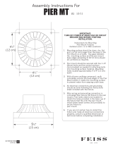
Figure 1. Diagram of the QV-PIER-HV-IPI
5-1/4
(133mm)
1/2
(13mm)
12
(306mm)
Ø8
(205mm)
42-5/8
(1082mm)
Ø8
(205mm)
12
(305mm)
ELECTRICAL
ACCESS
GAS LINE
ACCESS
34-3/4
(883mm)
4-1/16
(102mm)
4-1/2
(114mm)
4-3/4
(121mm)
2-5/16
(58mm)
37-7/16
(950mm)
17-15/16
(455mm)
24
(610mm)
21-9/16
(547mm)
32-5/16
(820mm)
21-9/16
(547mm)
42
(1067mm)
REAR VENT
COLLARS
ELECTRICAL
ACCESS
GAS LINE
ACCESS
GAS CONTROLS
& LABELS
SIDE GLASS
DOOR
TOP STANDOFFS
TOP VENT
COLLARS

12
Quadra-Fire • QV-PIER, QV-ST Series: HV-IPI • 2005-901 Rev. G • 2/06
Figure 3. Diagram of the QV-ST-HV-IPI
5-14
(133mm)
12
(306mm)
1/2
(13mm)
(4)
46-5/8
(1183mm)
42
(1067mm)
32-5/16
(821mm)
21-9/16
(548mm)
36-3/16
(919mm)
2-5/16
(58mm)
4-3/4
(121mm)
4-1/16
(102mm)
4-1/2
(114mm)
ELECTRICAL
ACCESS
GAS LINE
ACCESS
12
(305mm)
4-1/2
(114mm)
2-9/16
(64mm)
24
(610mm)
8-1/2
(216mm)
34-3/4
(882mm)
Ø8
(205mm)
Ø8
(205mm)
REAR VENT
COLLARS
ELECTRICAL
ACCESS
GAS LINE
ACCESS
GAS CONTROLS
& LABELS
SIDE GLASS
DOOR
TOP STANDOFFS
TOP VENT
COLLARS
Figure 2. Dimensions of the QV-ST-HV-IPI

13
Quadra-Fire • QV-PIER, QV-ST Series: HV-IPI • 2005-901 Rev. G • 2/06
3
Installing the Fireplace
Step 1. Locating the Fireplace
The diagram below shows space and clearance require-
ments for locating a fireplace within a room.
Figure 4A. Fireplace Dimensions and Locations
Clearance Requirements
The top, back, and sides of the fireplace are defined by
stand-offs. The minimum clearance to a perpendicular wall
extending past the face of the fireplace is one inch (25 mm).
The metal ends of the fireplace may NOT be recessed into
combustible construction.
Note: Refer to Figure 4B for dimensions and appliance
locations if installing a QV-PIER-HV unit with a Catalina
shelf and/or marble package.
Note: Refer to the Catalina installation instruction
included with kit for assembly and installation.
Figure 4B.
50-1/2 in.
34-1/2 in.
7 in.
47-1/2 in.
45-1/4 in.
13/16 in.
Marble sizes (inches):
Header.................................. 26 x 8
Side headers ..................45-1/2 x 8
Legs................................33-1/2 x 7
Í
45 -1/4 in.
(1149mm)
FINISHED
WALL
Fireplace Locations/Dimensions with
Catalina Shelf/Marble Package ONLY
Î
Î
Note: This location diagram MUST be followed when in-
stalling a QV-Pier-HV with a Catalina shelf/marble package
since the fireplace is installed further from finished wall.
36"
GLASS
GLASS
36"
GLASS
GLASS
GLASS
36"
36"
36"
QV-PIER-HV-IPI
TOP VIEW
QV-ST-HV-IPI
TOP VIEW

14
Quadra-Fire • QV-PIER, QV-ST Series: HV-IPI • 2005-901 Rev. G • 2/06
Minimum Clearances
from the Fireplace to Combustible Materials
Inches mm
Glass Sides or Ends.......... 36 .................... 914
Floor ................................... 0 ....................... 0
Rear Vent...........................1/2..................... 13
Metal Sides or Ends ..........1/2..................... 13
Top................................... 2 1/2 ................... 64
Ceiling* .............................. 31 .................... 787
For minimum clearances, see the direct vent termination
clearance diagrams on pages 25 and 26 in this manual.
Minimum Clearances
from the Vent Pipe to Combustible Materials
Inches mm
Vertical Sections. ............. 1 ................ 25
Horizontal Sections
Top..................................... 3 ................ 75
Bottom ............................... 1 ................ 25
Sides ................................. 1 ................ 25
At Wall Firestops
Top.................................. 2 1/2 ............63.7
Bottom ..............................1/2............... 13
Sides ................................. 1 ................ 25
* The clearance to the ceiling is measured from the top of
the unit, excluding the standoffs (see Figures 35 & 36).
The distance from the unit to combustible construction is to
be measured from the unit outer wrap surface to the com-
bustible construction, NOT from the screw heads that se-
cure the unit together.
!
WARNING: FRAMING DIMENSIONS ASSUME
USE OF 1/2 INCH THICK WALL COVERING
MATERIALS ON EXTERIOR OF FRAMING ONLY AND
NO SHEETROCK ON INTERIOR OF FRAMING.
Step 2. Framing the Fireplace
Fireplace framing can be built before or after the fireplace is
set in place. Framing should be positioned to accommo-
date wall coverings and fireplace facing material. The dia-
gram below shows framing reference dimensions.
CAUTION: MEASURE FIREPLACE DIMENSIONS AND
VERIFY FRAMING METHODS AND WALL COVERING
DETAILS BEFORE FRAMING.

15
Quadra-Fire • QV-PIER, QV-ST Series: HV-IPI • 2005-901 Rev. G • 2/06
Framing should be
constructed of 2 X 4
lumber or heavier.
Model A B C D E
QV-PIER-HV-IPI 42-1/8 42-1/2 23 35-3/4 48
QV-ST-HV-IPI 47-5/8 42-1/2 23 35-3/4 48
Figure 5. Framing Dimensions
NOTE: DIMENSIONS SHOWN IN INCHES
Shows center of 10” x 12” vent framing holes for top and rear venting. The center
of the hole is one inch (25.4mm) above the center of the horizontal vent pipe.
QV-PIER-HV-IPI
QV-ST-HV-IPI
D
B
C
A
A
C
B
E

16
Quadra-Fire • QV-PIER, QV-ST Series: HV-IPI • 2005-901 Rev. G • 2/06
NOTE: PIPES OVERLAP 1-1/4 INCHES
AT EACH JOINT.
Figure 6. DVP-Series Direct Vent Component Specifications (5-inch inner pipe / 8-inch outer pipe)
D
V
P
9
0
S
T
12-9/16
11-1/4
7-1/4
1-1/4 TYP
1/2 TYP
8-9/16
DVP36
DVP48
48
24
36
4
6
DVP4
DVP6
12
DVP12
2
MIN.
DVP12A
12-3/16
MAX.
DVP24
9-7/8
45.0
O
10-1/4
DVP45
14-1/4

17
Quadra-Fire • QV-PIER, QV-ST Series: HV-IPI • 2005-901 Rev. G • 2/06
Figure 7. Vent System Components and Termination Kits
Step 3. Installing the Vent System
A. Vent System Approvals
These models are approved to use DVP series direct vent
pipe components and terminations (see Figures 6 and 7).
Approved vent system components are labeled for identifi-
cation. This pipe is tested and listed as an approved com-
ponent of the fireplace. The pipe is tested to be run inside
an enclosed wall. There is no requirement for inspection
openings at each joint within the wall. There is no required
pitch for horizontal vent runs. NO OTHER VENTING SYS-
TEMS OR COMPONENTS MAY BE USED.
Detailed installation instructions are included with each vent
termination kit and should be used in conjunction with this
Installers Guide.
The flame and ember appearance may vary based on the
type of fuel burned and the venting configuration used.
Identifying Vent Components
The vent systems installed on this gas fireplace may in-
clude one, two, or three 90°
elbow assemblies. The rela-
tionships of vertical rise to horizontal run in vent configura-
tions using 90° elbows MUST BE strictly adhered to. The
rise to run relationships are shown in the venting drawings
and tables. Refer to the diagrams on the next several pages.
NOTE: Two 45° elbows may be used in place of one
90° elbow. Rise to run ratios in the vent system must
be followed if 45° elbows are used.
This model has 45
0
elbow built into this unit. It may be
positioned to vent either horizontal or vertical. Depending
on the installation, decide which direction the elbow should
be facing. Remove the 8 screws from the corner cover plate.
Position the 45
0
elbow as desired and replace the corner
cover plate with the 8 screws.
PVK-80
DVP-TRAP
DVK-01D DVK-TVCD
DVP-TVHW
Termination kits
DVP-TB1
HORIZONTAL
TERMINATION
WALL FIRESTOP
90 DEGREE
ELBOW
PIPE LENGTH
CEILING
FIRESTOP
VERTICAL
TERMINATION
STORM COLLAR
ROOF FLASHING
(IPI models only)

18
Quadra-Fire • QV-PIER, QV-ST Series: HV-IPI • 2005-901 Rev. G • 2/06
Figure 8
NOTE: On vertical venting
configurations you may
want to install the flue re-
strictor (385-128). See flue
restrictor installation in-
structions.
Flue Restrictor Instructions
1. Locate the flue restrictor which is in the manual
bag.
Figure 9
2. Break the Flue Restrictor into two pieces. Do this
by bending the part back and forth until it breaks
(see Figure 10).
V
CAP
FLUE
RESTRICTOR
STRAIGHT UP
VERTICAL VENTING
V (FT.)
50' MAX. (15.2 M)
Figure 10. Flue Restrictor
BREAK
HERE
1 2 3 4 5
SETTINGS
1 2 3 4 5
4.Center the Flue Restrictor on vent and secure in
place using two self-tapping screws (see Figure 11).
STRAIGHT OUT
HORIZONTAL VENTING
H
Max. Run
24" (610 mm)
Figure 12.
H
3. Match the amount of
vertical you have in the
system with the chart to
find the appropriate po-
sition to set the Flue Re-
strictor.
Figure 11
- CHART -
Vertical Settings
4' 1-1
8' 1-2
15' 2-2
20' 2-3
25' 3-3
30' 4-3
35' 4-4
40' 4-4
50' 4-5

19
Quadra-Fire • QV-PIER, QV-ST Series: HV-IPI • 2005-901 Rev. G • 2/06
NATURAL GAS
VENTING WITH ONE 90° ELBOW
V (FT.) H (FT.)
90
0
Elbow on top 2.5’ MAX. (64mm)
1' MIN. (305mm) 3' MAX. (914mm)
2' MIN. (610mm) 6' MAX. (1.83m)
3' MIN. (914mm) 9' MAX. (2.7m)
4' MIN. (1.22m) 12' MAX. (3.6m)
5’ MIN. (1.5m) 15’ MAX. (4.5m)
6’ MIN. (1.83m) 18’ MAX. (5.5m)
V + H = 50’ MAX. (15.2m)
Figure 14. Venting with One 90° Elbow
Figure 13. Venting with One 90° Elbow
V
H
H
V
PROPANE
VENTING WITH ONE 90° ELBOW
V (FT.) H (FT.)
90
0
Elbow on top 2’ MAX. (610mm)
1' MIN. (305mm) 2' MAX. (610mm)
2' MIN. (610mm) 4' MAX. (1.22m)
3' MIN. (914mm) 6’ MAX. (1.83m)
4' MIN. (1.22m) 8' MAX. (2.4m)
5’ MIN. (1.5m) 10' MAX. (3.0m)
6’ MIN. (1.83m) 12' MAX. (3.6m)
V + H = 50’ MAX. (15.2m)
NATURAL GAS - VENTING WITH ONE 90° ELBOW
V (FT.) H (FT.)
1' MIN. (305mm) 3' MAX. (914mm)
2' MIN. (610mm) 6' MAX. (1.83m)
3' MIN. (914mm) 9' MAX. (2.7m)
4' MIN. (1.22m) 12' MAX. (3.6m)
5’ MIN. (1.5m) 15’ MAX. (4.5m)
6’ MIN. (1.83m) 18’ MAX. (5.5m)
V + H = 50’ MAX. (15.2m)
(11.3m)
PROPANE - VENTING WITH ONE 90° ELBOW
V (FT.) H (FT.)
1' MIN. (305mm) 2' MAX. (610mm)
2' MIN. (610mm) 4' MAX. (1.22m)
3' MIN. (914mm) 6’ MAX. (1.83m)
4' MIN. (1.22m) 8' MAX. (2.4m)
5’ MIN. (1.5m) 10' MAX. (3.0m)
6’ MIN. (1.83m) 12' MAX. (3.6m)
V + H = 50’ MAX. (15.2m)

20
Quadra-Fire • QV-PIER, QV-ST Series: HV-IPI • 2005-901 Rev. G • 2/06
Figure 15. Venting with Two 90° Elbows
H
1
H
V
V
V
1
H
NATURAL GAS
VENTING WITH TWO 90° ELBOWS
V (FT.) H + H
1
(FT.)
90
0
Elbow on top 2.5’ MAX. (64mm)
1' MIN. (305mm) 3' MAX. (914mm)
2' MIN. (610mm) 6' MAX. (1.83m)
3' MIN. (914mm) 9' MAX. (2.7m)
4' MIN. (1.22m) 12' MAX. (3.6m)
5’ MIN. (1.5m) 15’ MAX. (4.5m)
6’ MIN. (1.83m) 18’ MAX. (5.5m)
V + H + H
1
= 50’ MAX. (15.2m)
PROPANE
VENTING WITH TWO 90° ELBOWS
V (FT.) H + H
1
(FT.)
90
0
Elbow on top 2’ MAX. (610mm)
1' MIN. (305mm) 2' MAX. (610mm)
2' MIN. (610mm) 4' MAX. (1.22m)
3' MIN. (914mm) 6’ MAX. (1.83m)
4' MIN. (1.22m) 8' MAX. (2.4m)
5’ MIN. (1.5m) 10' MAX. (3.0m)
6’ MIN. (1.83m) 12' MAX. (3.6m)
V + H + H
1
= 50’ MAX. (15.2m)
NATURAL GAS
VENTING WITH TWO 90° ELBOWS
V + V
1
(FT.) H (FT.)
90
0
Elbow on top 2.5’ MAX. (64mm)
1' MIN. (305mm) 3' MAX. (914mm)
2' MIN. (610mm) 6' MAX. (1.83m)
3' MIN. (914mm) 9' MAX. (2.7m)
4' MIN. (1.22m) 12' MAX. (3.6m)
5’ MIN. (1.5m) 15’ MAX. (4.5m)
6’ MIN. (1.83m) 18’ MAX. (5.5m)
V + V
1
+ H = 50’ MAX. (15.2m)
PROPANE
VENTING WITH TWO 90° ELBOWS
V + V
1
(FT.) H (FT.)
90
0
Elbow on top 2’ MAX. (610mm)
1' MIN. (305mm) 2' MAX. (610mm)
2' MIN. (610mm) 4' MAX. (1.22m)
3' MIN. (914mm) 6’ MAX. (1.83m)
4' MIN. (1.22m) 8' MAX. (2.4m)
5’ MIN. (1.5m) 10' MAX. (3.0m)
6’ MIN. (1.83m) 12' MAX. (3.6m)
V + V
1
+ H = 50’ MAX. (15.2m)
H + H
1
= 18’ MAX. (5.5m)
H + H
1
= 12’ MAX. (3.6m)
/