
Two-Stage Condensing gas Furnaces With Fixed & Variable Speed Blowers 95.0% AFUE
INSTALLATION INSTRUCTIONS
*TL Downflow Furnace
*TC Upflow / Horizontal Furnace
WARNING
FIRE OR EXPLOSION HAZARD
supplier.
WHAT TO DO IF YOU SMELL GAS
DO NOT DESTROY. PLEASE READ CAREFULLY & KEEP IN A SAFE PLACE FOR FUTURE REFERENCE.

2
TABLE OF CONTENTS
IMPORTANT SAFETY INFORMATION .............................. 3
REQUIREMENTS & CODES ..............................................4
Combustion Air Quality....................................................5
Heating Load ...................................................................5
Installation in a Garage....................................................5
Clearances to Combustible Materials .............................6
Operation of Furnace During Construction .....................6
COMBUSTION AIR & VENTING REQUIREMENTS ..........7
Direct Vent Systems ........................................................8
Conventional Vent Systems - Confined Spaces ..............8
Air From Inside .............................................................. 8
Outdoor Air from a Crawl Space or Vented Attic ........... 8
Outdoor Air Using Vertical Ducts ..................................8
Outdoor Air Using Horizontal Ducts ..............................8
Air Directly Through an Exterior Wall ............................9
Alternate Method of Providing Air from Outside: ...........9
Conventional Vent Systems - Unconfined Spaces ..........10
Category IV Venting .........................................................10
Vent Pipe Material ......................................................... 11
Vent Pipe Length & Diameter ........................................11
Vent Pipe Installation ....................................................11
Outdoor Terminations - Horizontal Venting ...................12
Outdoor Terminations - Vertical Venting .......................13
Vent Freezing Protection ...............................................13
Existing Installations ......................................................13
Condensate Disposal ......................................................13
CIRCULATING AIR REQUIREMENTS ............................... 14
Plenums & Air Ducts ........................................................14
Return Air Connections ...................................................14
Upflow & Horizontal Furnaces ....................................... 14
Downflow Furnaces .......................................................15
Supply Air Connections ...................................................15
Acoustical Treatments .....................................................15
FURNACE INSTALLATION ................................................ 15
General Requirements ....................................................15
Upflow Furnaces .............................................................. 15
Horizontal Furnaces ........................................................15
Downflow Furnaces .........................................................16
Installation on a concrete slab .......................................16
Inducer & Venting Options ...............................................16
Inducer Assembly Rotation ...........................................17
Pressure Switch Tubing ................................................17
Accessories .....................................................................17
Finish Flange .................................................................17
Rubber Grommets .........................................................18
PVC Components .........................................................18
Typical Orientation .................................................18
Alternate Orientation ..............................................18
Condensate Drain Lines ................................................19
Bottom Panel Removal ....................................................19
Alternate Bottom Panel Removal ..................................19
GAS SUPPLY & PIPING .....................................................20
Leak Check ...................................................................... 22
High Altitude Application (Natural Gas Only) ..................22
Converting from Natural Gas to LP / Propane .................23
ELECTRICAL WIRING .......................................................23
Line Voltage Wiring..........................................................23
Grounding ........................................................................24
Thermostat / Low Voltage Connections ..........................24
Single Stage AC & Two Stage Thermostat ...................25
Two-Stage AC & Two-Stage Thermostat ......................25
Autostaging for Single Stage Thermostats ......................25
Autostaging for Two-Stage Thermostats .........................26
Blower Speed Configuration ............................................26
Fixed Speed Blower Applications ..................................26
Variable Speed Blower Applications .............................26
Dehumidification Options ................................................26
START-UP & ADJUSTMENTS ...........................................27
Pre-Start Check List ........................................................27
Start-up Procedures ........................................................27
Verifying & Adjusting Input Rate ...................................... 27
Verifying & Adjusting Temperature Rise ..........................27
Heat Anticipator ...............................................................27
Verifying Burner Operation ..............................................28
Verifying Operation of the Supply Air Limit Switch .......... 28
OPERATING SEQUENCE ..................................................29
Heating Cycle ..................................................................29
Cooling Cycle ..................................................................29
Fan Mode .........................................................................29
MAINTENANCE ..................................................................29
FIGURES & TABLES ..........................................................31
Figure 28. *TC & *TL Cabinet Dimensions .................... 31
Airflow Data .....................................................................32
Table 6. *TC / *TL Heating / Cooling Airflows (CFM)
& Temperature Rises (°F) ................................32
Table 7. *TC / *TL Nominal Heating Airflows
(CFM) & Temperature Rises (° F) for Variable
Speed Furnaces ...............................................34
Table 8. *TC / *TL Nominal Cooling / Heat Pump
Airflows (CFM)for Variable Speed Furnaces ...35
Gas Information ...............................................................36
Table 9. Gas Flow Rates ...............................................36
Table 10. Gas Pipe Capacities ......................................36
Table 11. High Altitude Deration - Propane Gas ...........37
Table 12. Natural Gas Heating Values ..........................37
Table 13. High Altitude Deration - Natural Gas with
HIGH Heating Value ......................................38
Table 14. High Altitude Deration - Natural Gas with
LOW Heating Value .......................................38
Electrical Information .......................................................39
Figure 29. Two-Stage Fixed Speed Motor Control
Board ............................................................39
Figure 31. Two-Stage Furnace Control Board ..............39
Figure 30. Two-Stage Variable Speed
Motor Control Board .....................................39
Figure 32. Wiring Diagram for Two-Stage, Fixed
Speed Upflow Furnaces ...............................40
Figure 33. Wiring Diagram for Two-Stage, Fixed
Speed Downflow Furnaces ..........................41
Figure 34. Wiring Diagram for Two-Stage, Variable
Speed Upflow Furnaces ...............................42
Figure 35. Wiring Diagram for Two-Stage, Variable
Speed Downflow Furnaces ..........................43

3
WARNING:
be used with this product.
WARNING:
• Tominimizeequipmentfailureorpersonalinjury,itis
essential that only qualified individuals install, service, or
maintain this equipment. If you do not posses mechanical
skills or tools, call your local dealer for assistance.
• Followallprecautionsinthe literature, on tags, and
on labels provided with the equipment. Read and
thoroughly understand the instructions provided with
the equipment prior to performing the installation and
operational checkout of the equipment.
• Usecautionwhenhandlingthisapplianceorremoving
components. Personal injury can occur from sharp metal
edges present in all sheet metal constructed equipment.
• Donotstoreanyofthefollowingon,orincontactwith,
the unit: Rags, brooms, vacuum cleaners, or other
cleaning tools, spray or aerosol cans, soap powders,
bleaches, waxes, cleaning compounds, plastics or
plastic containers, paper bags or other paper products,
gasoline, kerosene, cigarette lighter fluid, dry cleaning
fluids, paint thinners, or other volatile fluids.
• Theinstallershouldbecomefamiliarwiththeunitswiring
diagram before making any electrical connections to
the unit. See Figure 32 (page 40), Figure 33 (page 41),
Figure 34 (page 42), & Figure 35 (page 43) or the unit
wiring label.
IMPORTANT SAFETY INFORMATION
INSTALLER: Please read all instructions before servicing
this equipment. Pay attention to all safety warnings and
any other special notes highlighted in the manual. Safety
markings are used frequently throughout this manual to
designate a degree or level of seriousness and should
not be ignored.
WARNING - indicates a potentially hazardous situation
that if not avoided, could result in personal injury or death.
CAUTION - indicates a potentially hazardous situation
that if not avoided, may result in minor or moderate injury
or property damage.
WARNING:
WARNING:
Venting Information ..........................................................44
Table 15. Vent Termination Clearances ........................ 44
Figure 36. Horizontal & Vertical Venting
(A Width Cabinets) .......................................45
Figure 37. Horizontal & Vertical Venting
(B, C, & D Width Cabinets) ..........................46
Figure 38. Horizontal & Vertical Venting
(B, C, & D Width Cabinets) ..........................47
Figure 39. Upflow Venting Options
(B, C, & D Width Cabinets) ..........................48
Figure 40. Horizontal Venting Options
(A Width Cabinets) .......................................49
Figure 41. Horizontal Venting Options
(B, C, & D Width Cabinets) ..........................50
Figure 42. Downflow Options ........................................51
TROUBLESHOOTING ........................................................52
Table 16. Furnace Control Board Fault Conditions .......52
Table 17. Motor Control Board Fault Conditions ...........52
FURNACE COMPONENTS ................................................52
Figure 43. Component Locations ..................................53
INSTALLATION / PERFORMANCE CHECK LIST ............112

4
REQUIREMENTS & CODES
WARNING:
• This furnace must be installed in accordance with
these instructions, all applicable local building codes
and the current revision of the National Fuel Gas Code
(NFPA54/ANSI Z223.1) or the Natural Gas and Propane
Installation Code, CAN/CGA B149.1.
• Useonlywithtypeofgasapprovedforthisfurnace.
Refer to the furnace rating plate.
• Installthisfurnaceonlyinalocationandpositionas
specified on page 6.
• Provideadequatecombustionandventilationairtothe
furnace space as specified on page 7, page 8,
page 9, & page 10.
• Provideadequateclearancesaroundtheventairintake
terminal as specified in Figure 7 (page 12), Figure 8 (page
12)
, Figure 9 (page 12), & Figure 10 (page 12).
• Combustion products must be discharged outdoors.
Connect this furnace to an approved vent system only,
as specified on page 10, page 11, page 12, & page
13
.
• Never test for gas leaks with an open ame. Use
a commercially available soap solution to check all
connections. See page 22.
• Thisfurnaceisdesignedtooperatewithamaximum
external pressure rise of 0.5 inches of water column.
Consult Table 6 (page 32), Table 7 (page 34), & Table 8
(page 35)
, and the rating plate for the proper circulating
air flow and temperature rise. It is important that the duct
system be designed to provide the correct flow rates
and external pressure rise. An improperly designed duct
system can result in nuisance shutdowns, and comfort
or noise issues.
• Whensupplyductscarryaircirculatedbythefurnace
to areas outside the space containing the furnace, the
return air shall also be handled by duct(s) sealed to
the furnace casing and terminating in the conditioned
space. See page 14.
• Agas-redfurnaceforinstallationinaresidentialgarage
must be installed as specified on page 5.
• Thisfurnaceisnotapprovedforinstallationinmobile
homes. Installing this furnace in a mobile home could
cause fire, property damage, and/or personal injury.
• The Commonwealth of Massachusetts requires
compliance with regulation 248 CMR 4.00 and 5.00 for
installation of through – the – wall vented gas appliances
as follows:
1. For direct-vent appliances, mechanical-vent heating
appliances or domestic hot water equipment, where the
bottom of the vent terminal and the air intake is installed
below four feet above grade the following requirements
must be satisfied:
a.) A carbon monoxide (CO) detector and alarm shall
be placed on each floor level where there are
bedrooms. The detector shall comply with NFPA
720 (2005 Edition) and be mounted in the living
area outside the bedroom(s).
b.) A (CO) detector shall be located in the room that
houses the appliance or equipment and shall:
•Bepoweredbythesameelectricalcircuitasthe
appliance or equipment. Only one service switch
shall power the appliance and the (CO) detector;
•Havebatteryback-uppower;
•MeetANSI/UL2034Standardsandcomplywith
NFPA 720 (2005 Edition); and Approved and listed
by a Nationally Recognized Testing Laboratory
as recognized under 527 CMR.
c.) A Product-approved vent terminal must be
used, and if applicable, a product-approved air
intake must be used. Installation shall be in strict
compliance with the manufacturer’s instructions.
A copy of the installation instructions shall remain
with the appliance or equipment at the completion
of the installation.
d.) A metal or plastic identification plate shall be
mounted at the exterior of the building, four feet
directly above the location of vent terminal. The
plate shall be of sufficient size, easily read from
a distance of eight feet away, and read “Gas Vent
Directly Below”.
2. For direct-vent appliances, mechanical-vent heating
appliances or domestic hot water equipment where the
bottom of the vent terminal and the air intake is installed
above four feet above grade the following requirements
must be satisfied:
a.) A (CO) detector and alarm shall be placed on each
floor level where there are bedrooms. The detector
shall comply with NFPA 720 (2005 Edition) and be
mounted in the living area outside the bedroom(s).
b.) The (CO) detector shall:
•Belocatedintheroomthathousestheappliance
or equipment;
•Behard-wiredorbatterypoweredorboth.
•ShallcomplywithNFPA720(2005Edition).
c.) A product-approved vent terminal must be
used, and if applicable, a product-approved air
intake must be used. Installation shall be in strict
compliance with the manufacturer’s instructions.
A copy of the installation instructions shall remain
with the appliance or equipment at the completion
of the installation.

5
The information listed below is for reference purposes only
and does not necessarily have jurisdiction over local or
state codes. Always consult with local authorities before
installing any gas appliance.
• US:NationalFuelGasCode(NFGC),AirforCombustionand
Ventilation
• CANADA: Natural Gas and Propane Installation Codes
(NSCNGPIC), Venting Systems and Air Supply for Appliances
• USandCANADA:AirConditioningContractorsAssociation
(ACCA) Manual D, Sheet Metal and Air Conditioning
Contractors National Association (SMACNA), or American
Society of Heating, Refrigeration, and Air Conditioning
Engineers (ASHRAE) Fundamentals Handbook
Electrical Connections
• US:NationalElectricalCode(NEC)ANSI/NFPA70
• CANADA:CanadianElectricalCodeCSAC22.1
Gas Piping & Gas Pipe Pressure Testing
• US:NFGCandNationalPlumbingCodes
• CANADA:NSCNGPIC
General Installation
• US:Currentedition of theNFGCandtheNFPA 90B.For
copies, contact the National Fire Protection Association Inc.,
Batterymarch Park, Quincy, MA 02269; or American Gas
Association, 400 N. Capitol, N.W., Washington DC 20001 or
www.NFPA.org
• CANADA:NSCNGPIC.Foracopy,contactStandardSales,
CSA International, 178 Rexdale Boulevard, Etobicoke
(Toronto), Ontario, M9W 1R3 Canada
• US:(NFGC)NFPA54–1999/ANSIZ223.1andtheInstallation
Standards, Warm Air Heating and Air Conditioning Systems
ANSI/NFPA 90B.
• CANADA:CAN/CGA-B149.1and.2–M00NationalStandard
of Canada. (NSCNGPIC)
CAUTION:
To maximize heat exchanger life, the combustion air
must be free of chemicals that can form corrosive acidic
compounds in the combustion gases. The recommended
source of combustion air is to use outdoor air. However,
the use of indoor air in most applications is acceptable
except as listed:
• If the furnace is installed in a conned space, it is
required that the necessary combustion air come from
the outdoors by way of attic, crawl space, air duct, or
direct opening. For Installations in confined spaces, see
page 7 for combustion air requirements.
• Installationsintheselocationsmayrequireoutdoorair
for combustion, due to chemical exposures:
Commercial buildings
Buildings with indoor pools
Furnaces installed in laundry rooms
Furnaces installed in hobby or craft rooms
Furnaces installed near chemical storage areas
• Exposuretothefollowingsubstancesinthecombustion
air supply may require outdoor air for combustion:
Permanent wave solutions
Chlorinated waxes and cleaners
Chlorine based swimming pool chemicals
Water softening chemicals
De-icing salts or chemicals
Carbon Tetrachloride
Halogen type refrigerants
Cleaning solvents (perchloroethylene)
Printing inks, paint removers, varnishes, etc.
Hydrochloric Acid
Cements and glues
Antistatic fabric softeners
Masonry acid washing materials
Heating Load
This furnace should be sized to provide the design heating
load requirement. Heating load estimates can be made
using approved methods available from Air Conditioning
Contractors of America (Manual J); American Society of
Heating, Refrigerating, and Air Conditioning Engineers;
or other approved engineering methods.
. The ductwork should
be appropriately sized to the capacity of the furnace to
ensure its proper airflow rating.
For installations above 2,000 ft., the furnace should have
a sea level input rating large enough that it will meet the
heating load after deration for altitude.
Two-stage furnaces operate at two input rates to better
meet heating loads. The lower heating rate (low fire) is
65% of the high fire rate. The greatest degree of control
over the furnace can be gained by controlling it with a two
stage thermostat. This allows the thermostat to directly
request either high or low fire. However, it is possible to
operate the furnace using a single stage thermostat. In
this application the furnace control can be set to increase
from low to high fire, based on a timer. See Autostaging
for Single Stage Thermostats (page 25).
Furnaces are properly sized to meet the expected
maximum heating load. But this load occurs infrequently.
So, during more moderate weather, the furnace is likely to
use low fire a considerable part of the time. This is normal
and has the benefit of quieter and more efficient operation.
Installation in a Garage
This Gas-fired furnace may be installed in a residential
garage with the provision that the burners and igniter
are located no less than 18 inches (457mm) above the
floor. The furnace must be located or protected to prevent
physical damage by vehicles.

6
TOP
FRONT
UPFLOW
APPLICATIONS
HORIZONTAL
APPLICATIONS
VENT
TOP
FRONT
DOWNFLOW
APPLICATIONS
SIDE
TOP
BOTTOM
VENT
VENT
FRONT
BACK
BACK
SIDE
LEFT SIDE
LEFT SIDE
RIGHT SIDE
RIGHT SIDE
CLEARANCES TO COMBUSTIBLE MATERIALS
Left Side ................. 0 Inches
Top ..........................0 Inches
Right Side ............... 0 Inches
Front ........................
†
4 Inches
Vent ........................ 0 Inches Back........................ 0 Inches
clearance is 36 in.
Figure 1.
WARNING:
This furnace is Design Certified in the U.S. and Canada
by CSA International for the minimum clearances to
combustible materials. NOTE: The furnace is listed for
installation on combustible or non-combustible flooring.
However, wood is the only combustible flooring allowed
for installation. Downflow models must use the appropriate
subase kit when installing over a wood floor. To obtain
model number and specific clearance information, refer
to the furnace rating plate, located inside of the furnace
cabinet.
Access for positioning and servicing the unit must be
considered when locating unit. The need to provide
clearance for access to panels or doors may require
clearance distances over and above the requirements.
See Figure 1 for minimum clearance requirements.
CAUTION:

7
COMBUSTION AIR & VENTING
REQUIREMENTS
WARNING:
CARBON MONOXIDE POISONING HAZARD
while all other appliances connected to the
and windows and all doors between the space
in which the appliance(s) connected to the
6. Follow the lighting instructions. Place the
appliance being inspected into operation.
corrected in accordance with the National Fuel
Codes.
IMPORTANT INFORMATION:
the NFGC.
with the National Fuel Gas Code (NFGC) and all
applicable local codes.
cause corrosion. The inlet pipe should not be placed
page 5.
WARNING:
WARNING:
building chase.
This condensing furnace is certified for installation either as
a Direct Vent (2-pipe) or Conventional (1-pipe) appliance.
Direct Vent appliances draw combustion air from the
outdoors and vent combustion products back outside.
Installation with air taken from around the furnace is often
referred to as Conventional installation - i.e. only the vent
(exhaust) pipe is provided.
Another important consideration when selecting one or
two pipe installation is the quality of the Indoor air which
can sometimes be contaminated with various household
chemicals . These chemicals can cause severe corrosion
in the furnace combustion system. A 2-pipe installation

8
has the additional advantage that it isolates the system
from the effects of negative pressure in the house.
CAUTION:
Fuel Gas Code.
Air openings on top of the furnace and openings in closet
doors or walls must never be restricted. If the furnace is
operated without adequate air for combustion, the flame
roll-out switch will open, turning off the gas supply to the
burners.
IMPORTANT NOTE
Direct vent appliances draw combustion air from the
outdoors and vent combustion products back outside,
isolating the entire system from the indoor space. It is
important to make sure that the whole system is sealed
and clearances to combustibles are maintained regardless
of the installation being in a confined or unconfined space.
Spaces
A confined space is an area with volume less than 50
cubic feet per 1,000 Btuh of the combined input rates of
all appliances drawing combustion air from that space.
Furnace closets, small equipment rooms and garages are
confined spaces. Furnaces installed in a confined space
which supply heated air to areas outside the space must
draw return air from outside the space and must have the
return air ducts tightly sealed to the furnace. Ducts must
have cross - sectional area at least as large as the free area
of their respective openings to the furnace space. Attics
or crawl spaces must connect freely with the outdoors if
they are the source of air for combustion and ventilation.
The required sizing of these openings is determined by
whether inside or outside air is used to support combustion,
the method by which the air is brought to the space, and
by the total input rate of all appliances in the space. In
all cases, the minimum dimension of any combustion air
opening is 3 inches.
Air From Inside
If combustion air is taken from the heated space, the two
openings must each have a free area of at least one square
inch per 1,000 Btuh of total input of all appliances in the
confined space, but not less than 100 square inches of
free area. See Example and Figure 2.
EXAMPLE
If the combined input rate of all appliances is less than
or equal to 100,000 Btuh, each opening must have
a free area of at least 100 in
2
. If the combined input
rate of all appliances is 120,000 Btuh, each opening
must have a free area of at least 120 in
2
.
Outdoor Air from a Crawl Space or Vented
Attic
When the openings can freely exchange air with the
outdoors, each opening shall have a minimum free area
of 1 square inch per 4,000 Btuh of total appliance input.
The openings shall exchange directly, or by ducts, with
the outdoor spaces (crawl or attic) that freely exchange
with the outdoors. See Figure 3 (page 9).
Outdoor Air Using Vertical Ducts
If combustion air is taken from outdoors through vertical
ducts, the openings and ducts must have a minimum free
area of one square inch per 4,000 Btuh of total appliance
input. See Figure 4 (page 9).
Figure 2.
TOTAL INPUT
RATING (BTUH)
MINIMUM FREE AREA
(EACH OPENING)
ROUND DUCT
DIAMETER
38,000 100 sq. In 12 inches
60,000 100 sq. In 12 inches
80,000 100 sq. In 12 inches
100,000 100 sq. In 12 inches
120,000 120 sq. In 13 inches
140,000 140 sq. In 14 inches
160,000 160 sq. In 15 inches
Vent or
Chimney
Furnace
Water
Heater
12” Max.
12” Max.
See
Notes
See
Notes
NOTES:
Each opening must be
at least 100 sq. in. or
1 sq. in. per 1,000 Btuh
of total input rating,
whichever is greater.
Openings must start at
no more than 12 inches
from the top and bottom
of the enclosure.

9
Outdoor Air Using Horizontal Ducts
If combustion air is taken from outdoors through horizontal
ducts, the openings and ducts must have a minimum free
area of one square inch per 2,000 Btuh of total appliance
input. Ducts must have cross - sectional area at least as
large as the free area of their respective openings to the
furnace space. See Figure 5.
Air Directly Through an Exterior Wall
If combustion air is provided directly through an exterior
wall, the two openings must each have free area of at
least one square inch per 4,000 Btuh of total appliance
input. See Figure 6.
Figure 4.
Through Vertical Ducts
TOTAL INPUT
RATING (BTUH)
MINIMUM FREE AREA
(EACH OPENING)
ROUND DUCT
DIAMETER
38,000 10 sq. In 4 inches
60,000 15 sq. In 5 inches
80,000 20 sq. In 5 inches
100,000 25 sq. In 6 inches
120,000 30 sq. In 6 inches
140,000 35 sq. In 7 inches
160,000 40 sq. In 8 inches
Air Duct must be
at least 1 sq. in.
per 4,000 Btuh of
total input rating.
Ducts must
extend above
attic insulation.
Air Duct must be
at least 1 sq. in.
per 4,000 Btuh of
total input rating.
Ventilation Louvers
at each end of attic
Attic
Insulation
12" Max
Furnace
Water
Heater
Vent or
Chimney
Water
Heater
Vent or
Chimney
-
-
-
-
-
-
-
-
-
-
-
-
-
-
-
-
-
-
Furnace
Ventilation Louvers For
Unheated Crawl Space
-
-
-
-
-
-
-
-
-
Inlet Air
Ventilation Louvers
(each end of attic)
NOTE: Air openings shall
each have a free area of
not less than one square
inch per 4,000 Btuh of the
total input rating of all
equipment in the enclosure
.
-
-
-
-
-
-
-
-
-
Alter
nate
Air Inlet
Outlet
Air
Figure 3.
Space or Vented Attic
Figure 5.
Through Horizontal Ducts
TOTAL INPUT
RATING (BTUH)
MINIMUM FREE AREA
(EACH OPENING)
ROUND DUCT
DIAMETER
38,000 20 sq. In 5 inches
60,000 30 sq. In 6 inches
80,000 40 sq. In 7 inches
100,000 50 sq. In 8 inches
120,000 60 sq. In 9 inches
140,000 70 sq. In 10 inches
160,000 80 sq. In 10 inches
Furnace
Water
Heater
Air Ducts must be
at least 1 sq. in.
per 2,000 Btuh of
total input rating.
Vent or
Chimney
Air Duct
Air Duct
TOTAL INPUT
RATING (BTUH)
MINIMUM FREE AREA
(EACH OPENING)
ROUND DUCT
DIAMETER
38,000 10 sq. In 4 inches
60,000 15 sq. In 5 inches
80,000 20 sq. In 5 inches
100,000 25 sq. In 6 inches
120,000 30 sq. In 6 inches
140,000 35 sq. In 7 inches
160,000 40 sq. In 8 inches
NOTE:
Each opening to outside
must be at least 1 sq. in. per
4,000 Btuh of total input rating.
12" Max.
-
-
-
-
-
-
-
-
-
-
-
-
-
-
-
-
-
-
Furnace
Water
Heater
Vent or
Chimney
12"
Max
See
Note
See
Note
Figure 6.
Through an Exterior Wall

10
Alternate Method of Providing Air from Out-
side:
If acceptable under local Codes, it is permitted to provide
outside air using one opening (See NFGC). Generally,
confined spaces must have 2 openings in the space for
combustion air. One opening must be within 12 inches of
the ceiling, and the other must be within 12 inches of the
floor. However, an alternative method recently adopted by
the NFGC uses one opening within 12 inches of the top
of the space. This method may be used if it is acceptable
to the local codes.
THE FOLLOWING CONDITIONS MUST BE MET:
1. The opening must start within 12” of the top of the
structure and connect with the out of doors through
vertical or horizontal ducts or be ducted to a crawl or
attic space that connects with the out of doors.
2. The opening must have a minimum free area of 1 in
2
.
per 3,000 Btu per hour of the total input rating of all
equipment located in the enclosure.
3. The free area must not be less than the sum of all the
areas of the vent connectors in the enclosure.
Spaces
An unconfined space is an area including all rooms not
separated by doors with a volume greater than 50 cubic
feet per 1,000 Btuh of the combined input rates of all
appliances which draw combustion air from that space.
In general, a furnace installed in an unconfined space will
not require outside air for combustion. However, in homes
built for energy efficiency (low air change rates), it may
be necessary to provide outside air to ensure adequate
combustion and venting, even though the furnace is located
in an unconfined space. See Example below.
EXAMPLE
A space with a water heater rated at 45,000 Btuh input
and a furnace rated at 75,000 Btuh requires a volume of
6,000 cubic feet [50 x (45 + 75) = 6,000] to be considered
unconfined. If the space has an 8 foot ceiling, the floor
area of the space must be 750 sq. ft. (6,000 / 8 = 750).
WARNING:
This furnace is classified as a “Category IV” appliance,
which requires special venting materials and installation
procedures. This section specifies installation requirements
for Conventional (1-pipe) and Direct Vent (2-pipe) piping.
For 1- pipe installations, install vent piping as described in
this section and provide air for combustion and ventilation
according to page 7, page 8, page 9, & page 10.
The length of vent and combustion air piping for either
type of installation are shown in Table 1.
Table 1. Vent Pipe Lengths
FURNACE
MODELS
(BTU)
FURNACE
INSTALLATION
SINGLE VENT PIPE LENGTH (FT.)
WITH 1 LONG RADIUS ELBOW*
DUAL VENT PIPE LENGTH (FT.)
WITH 1 LONG RADIUS ELBOW ON EACH PIPE*
OUTLET
2” DIAMETER
OUTLET
3” DIAMETER
INLET / OUTLET
2” DIAMETER
INLET / OUTLET
3” DIAMETER
38,000
Upflow 90 90 90 90
Horizontal 50 90 50 90
60,000
Upflow 90 90 90 90
Horizontal 50 90 50 90
Downflow 30 90 30 90
80,000
Upflow 40 90 40 90
Horizontal 30 90 30 90
Downflow 30 90 30 90
100,000
Upflow 30 90 30 90
Horizontal 30 90 30 90
Downflow 30 90 25 90
120,000
Upflow N/A 90 N/A 90
Horizontal N/A 90 N/A 90
Downflow N/A 90 N/A 90
*NOTES:
1. Subtract 2.5 ft. for each additional 2 inch long radius elbow, 5 ft. for each additional 2 inch short radius elbow, 3.5 ft. for each additional 3 inch
long radius elbow, and 7 ft. for each additional 3 inch short radius elbow. Subtract 5 ft for each 2” tee and 8 ft for each 3” tee. Two 45 degree
elbows are equivalent to one 90 degree elbow.
2. This table applies for elevations from sea level to 2,000 ft. For higher elevations, decrease pipe lengths by 8% per 1,000 ft of altitude.

11
Category IV appliances operate with positive vent pressure
and therefore require vent systems which are thoroughly
sealed. They also produce liquid condensate, which is
slightly acidic and can cause severe corrosion of ordinary
venting materials. Furnace operation can be adversely
affected by restrictive vent and combustion air piping.
The inducer assembly on this furnace can be rotated to
vent the flue products out of the left or right side of the
furnace. This increases the flexibility of which direction
the vent pipe can exit the furnace.
Vent Pipe Material
Vent and combustion air pipe and fittings must be one
of the following materials in the list and must conform to
the indicated ANSI/ASTM standards.
MATERIALS STANDARDS
Schedule 40PVC ............................................................... D1785
PVC-DWV .......................................................................... D2665
SDR-21 & SDR-26 ............................................................. D2241
ABS-DWV .......................................................................... D2661
Schedule 40 ABS .............................................................. F628
Foam / Cellular Core PVC ................................................. F891
*PolyPro
®
by DuraVent ...................................................... ULC-S636
CPVC ................................................................................. D1784
*When using PolyPro
®
, all venting and fittings must be from the same
manufacturer with no interchanging of other materials. Refer to specific
instructions supplied with the PolyPro vent kits
Cement must conform to ASTM Standard D2564 for PVC
and Standard D2235 for ABS. PVC primer must meet
standard ASTM F656. When joining PVC piping to ABS,
use PVC solvent cement. (See procedure specified in
ASTM Standard D3138)
In Canada, all plastic vent pipes and fittings including
any cement, cleaners, or primers must be certified as a
system to ULC S636. However this requirement does not
apply to the finish flanges or piping internal to the furnace.
Vent Pipe Length & Diameter
In order for the furnace to operate properly, the combustion
air and vent piping must not be excessively restrictive.
• Theventingsystemshouldbedesignedtohavethe
minimum number of elbows or turns.
• Transitiontothenalventdiametershouldbedoneas
close to the furnace outlet as practical.
• Alwaysusethesamesizeoralargerpipeforcombustion
air that is used for the exhaust vent.
Table 1 indicates the maximum allowable pipe length for
a furnace of known input rate, when installed with piping
of selected diameter and number of elbows. To use the
table, the furnace input rate, the centerline length and the
number of elbows on each pipe must be known.
When estimating the length of vent runs, consideration
must be made to the effect of elbows and other fittings.
This is conveniently handled using the idea of “equivalent
length”. This means the fittings are assigned a linear
length that accounts for the pressure drop they will cause.
For example: a 2” diameter, long radius elbow is worth
the equivalent of 2.5 feet of linear run. A 90 degree tee
is worth 7 ft.
The equivalent lengths of tees and various elbows are
listed in Table 1 . Measure the linear length of the vent run
and then add in the equivalent length of each fitting. The
total length, including the equivalent fitting lengths, must
be less than the maximum length specified in Table 1.
Vent Pipe Installation
CAUTION:
This furnace has been certified for installation with zero
clearance between vent piping and combustible surfaces.
However, it is good practice to allow space for convenience
in installation and service.
• In the absence of local codes, the location of any
combustion air inlet relative to any vent terminal must
be at least 8 inches. This includes installations involving
more than one furnace.
• Thequalityofoutdoorairmustalsobeconsidered.Be
sure that the combustion air intake is not located near
a source of solvent fumes or other chemicals which
can cause corrosion of the furnace combustion system.
(See list of substances on
page 5).
• Routepipingasdirectaspossiblebetweenthefurnace
and the outdoors. Horizontal piping from inducer to
the flue pipe must be sloped 1/4” per foot to ensure
condensate flows towards the drain tee or PVC trap.
Longer vent runs require larger pipe diameters. Refer
to the Inducer & Venting Options section on page 17
for additional information.
• IfaDirectVent(2-pipe)systemisused,thecombustion
air intake and the vent exhaust must be located in the
same atmospheric pressure zone. This means both
pipes must exit the building through the same portion
of exterior wall or roof as shown in Figure 7, Figure 8,
Figure 9
, & Figure 10.
• Pipingmustbemechanicallysupportedsothatitsweight
does not bear on the furnace. Pipe supports must be
installed a minimum of every 5 feet along the vent run
to ensure no displacement after installation. Supports
may be at shorter intervals if necessary to ensure that
there are no sagging sections that can trap condensate.
See Figure 36 (page 45) and Figure 37 (page 46). It is
recommended to install couplings along the vent pipe,
on either side of the exterior wall. These couplings may
be required by local code.
• Ifbreakableconnectionsarerequiredinthecombustion
air inlet pipe (if present) and exhaust vent piping, then
straight neoprene couplings for 2” or 3” piping with
hose clamps can be used. These couplings can be
ordered through your local furnace distributor. To install
a coupling:
1. Slide the rubber coupling over the end of the pipe that
is attached to the furnace and secure it with one of the
hose clamps.

12
2. Slide the other end of the rubber coupling onto the other
pipe from the vent.
3. Secure the coupling with the second hose clamp,
ensuring that the connection is tight and leak free.
Outdoor Terminations - Horizontal Venting
• Vent and combustion air intake terminations shall
be installed as depicted in Figure 7 & Figure 8 and in
accordance with these instructions:
• Ventterminationclearancesmustbeconsistentwiththe
NFGC, ANSI 2223.1/NFPA 54 and/or the CSA B149.1,
Natural Gas and Propane Installation Code.
Table 15
(page 44)
lists the necessary distances from the vent
termination to windows and building air intakes.
• Vent and combustion air intake terminations must
be located to ensure proper furnace operation and
conformance to applicable codes. A vent terminal
must be located at least 3 feet above any forced air
inlet located within 10 feet. This does not apply to the
combustion air inlet of a direct vent (two pipe) appliance.
In Canada, CSA B149.1, takes precedence over these
instructions. See Table 15.
• Allminimumclearancesmustbemaintainedtoprotect
building materials from degradation by flue gases. See
Figure 7.
• Foroptimalperformance,ventthefurnacethrougha
wall that experiences the least exposure to winter winds.
• The vent termination shall be located at least 3 ft.
horizontally from any electric meter, gas meter, regulator
and any relief equipment. These distances apply ONLY
to U.S. installations. In Canada, CSA B149.1, takes
precedence over these instructions.
• Donotinstalltheventterminalsuchthatexhaustis
directed into window wells, stairwells, under decks
or into alcoves or similar recessed areas, and do not
terminate above any public walkways.
• Ifventinghorizontally,asidewallventkitisavailable
according to the pipe diameter size of the installation.
For 2 inch pipe use side wall vent kit #904617, and
for 3 inch pipe use kit #904347.
• Concentricventterminationkitsareavailableforuse
with these furnaces. For 2 Inch pipe use kit #904952
and for 3 inch pipe use kit # 904953.
Figure 9. Alternate Horizontal Vent Installation
Support
NOTE: Vent Configuration to Provide
12" Minimum height above Snow Level.
1/2"
Armaflex
Insulation or
Equivalent
(if required)
12" Above
Maximum
Expected
Snow Level
19" Max.
(See Note)
Outside
Wall
12” min. to maximum
expected snow level
(both pipes)
90° Elbow
Exhaust vent
option B
Exhaust vent
option A
Mounting kit faceplate
secured to wall with screws
(both pipes)
Combustion
air inlet
Exhaust vent
option C
18” Min.
36” Max.
8” Min.
36” Max.
(all positions)
Figure 7. Inlet & Exhaust Pipe Clearances
Note 2
Mechanical draft
vent terminal
Direct vent
terminal
50,000 Btuh
or less
Forced air inlet
Direct vent
terminal - more
than 50,000 Btuh
Mechanical
draft vent
terminal
Mechanical
draft vent
terminal
Less
than
10 ft.
3 ft.
NOTES:
1. All dimensions shown are
minimum requirements.
2. Exterior vent terminations must
be located at least 12” above the
maximum expected snow level.
Note 2
4 ft
4 ft
12 in.
12 in.
9 in.
Note 2
Figure 8. Vent Locations
Figure 10.
Combustion Air
Exhaust Vent
12” Above Maximum
Expected Snow Level
(Both pipes)
Elbows on the combustion air
inlet must be positioned pointing
away from the exhaust vent.
8" Min.
36" Max.
Plumbing Vent Roof Boot
(Both Pipes)

13
Existing Installations
When an existing furnace is removed from a vent system
serving other appliances, the existing vent system may
not be sized properly to vent the remaining appliances
(For example: water heater). An improperly sized venting
system can result in the formation of condensate, leakage,
or spillage. The existing vent system should be checked
to make sure it is in compliance with NFGC and must be
brought into compliance before installing the furnace.
NOTE: If replacing an existing furnace, it is possible you
will encounter an existing plastic venting system that is
subject to a Consumer Product Safety Commission recall.
The pipes involved in the recall are High Temperature
Plastic Vent (HTPV).
these pipes This
recall does not apply to other plastic vent pipes, such
as white PVC or CPVC. Check for details on the CPSC
website or call their toll-free number (800) 758-3688.
Condensate Disposal
The method for disposing of condensate varies according
to local codes. Consult your local code or authority having
jurisdiction.
Each of the condensate drain lines must be J-trapped
using field supplied parts. After the condensate lines are
J-trapped, they may be combined together into a single
run to the drain. The drain lines must be routed downward
to ensure proper drainage from furnace.
Neutralizer kit P/N 902377 is available for use with this
furnace.
the kit.
For Installations where there is limited clearance for the
J-Trap (such as an attic where it may be installed between
ceiling joists), either side of the J-Trap can be shortened
to a minimum of 3 Inches. See Figure 11, (page 16).
• Whentheventpipemustexitanexteriorwallcloseto
the grade or expected snow level where it is not possible
to obtain clearances shown in Figure 7 (page 12), a
riser may be provided as shown in Figure 9. Insulation
is required to prevent freezing of this section of pipe.
See Table 2 (page 13) for vent freezing protection.
Outdoor Terminations - Vertical Venting
Termination spacing requirements from the roof and from
each other are shown in Figure 10. The roof penetration
must be properly flashed and waterproofed with a plumbing
roof boot or equivalent flashing. Vent and combustion air
piping may be installed in an existing chimney which is
not in use provided that:
• Boththeexhaustventandairintakerunthelengthof
the chimney.
• Thetopofthechimneyissealedandweatherproofed.
• The termination clearances shown in
Figure 10 are
maintained.
• Noothergasredorfuel-burningequipmentisvented
through the chimney.
Vent Freezing Protection
CAUTION:
be insulated with 1/2 inch thick sponge rubber
icing.
• Table 2 (page 13) lists the maximum length of flue pipe
that can travel through an unconditioned space or an
exterior space. The total vent length must not exceed
the lengths noted in Table 1 (page 10). For Canadian
installations, please refer to the Canadian Installation
Code (CAN/CGA-B149.1) and/or local codes.
• Forextremelycoldclimatesorforconditionsofshort
furnace cycles (i.e. set back thermostat conditions) the
last 18 inches of vent pipe can be reduced. It is acceptable
to reduce from 3” to 2-1/2”, 3” to 2”, or 2” to 1-1/2” if
the total vent length is at least 15 feet in length and the
vent length is within the parameters specified in Table 1.
The restriction should be counted as 3 equivalent feet.
Smaller vent pipes are less susceptible to freezing, but
must not be excessively restrictive. The length of the 2
inch pipe must not be longer than 18 inches.
• Iffurnaceisinstalledhorizontally,makesurethedrainage
port on the in-line drain assembly is pointed downward
to ensure proper drainage of condensate. See Figure
40 (page 49)
& Figure 41 (page 50).
• To prevent debris or creatures from entering the
combustion system, a protective screen may be installed
over the combustion air intake opening. The screens
hole size must be large enough to prevent air restriction.
WINTER DESIGN
TEMPERATURE
MAXIMUM FLUE PIPE LENGTH (FEET)
IN UNCONDITIONED & EXTERIOR SPACES
WITHOUT INSULATION WITH INSULATION*
20 45 70
0 20 70
-20 10 60
*NOTE: Insulation thickness greater than 3/8 inch, based on an
R value of 3.5 (ft x F x hr) / (BTU x in.)
Table 2. Vent Protection

14
the coil must be installed downstream (on the outlet
side) of the furnace or in parallel with the furnace.
• If a cooling system is installed in parallel with the
furnace, a damper must be installed to prevent chilled
air from entering the furnace and condensing on the heat
exchanger. If a manually operated damper is installed,
it must be designed so that operation of the furnace is
prevented when the damper is in the cooling position
and operation of the cooling system is prevented when
the damper is in the heating position.
• Itis goodpracticetosealall connectionsandjoints
with industrial grade sealing tape or liquid sealant.
Requirements for sealing ductwork vary from region
to region. Consult with local codes for requirements
specific to your area.
Return Air Connections
• In applications where the supply ducts carry heated
air to areas outside the space where the furnace is
installed, the return air must be delivered to the furnace
by duct(s) secured to the furnace casing, running full
size and without interruption.
• Positionthefurnacewiththereturnairductworkensuring
even alignment of furnace (or coil casing) air opening
and return air duct. NOTE: The ductwork must have an
opening equal to that of the return air opening of the
furnace (or coil casing). See Figure 28 (page 31) for
return air opening size.
Upflow & Horizontal Furnaces
• The return air ductwork may be connected to the left
side, right side, or bottom of the furnace. NOTE: If
using the left or right side of the furnace for return air,
the bottom panel (Figure 28) must not be removed from
the bottom of the furnace.
WARNING:
• Side Return Installations: To attach the return air duct
to the left or right side of the furnace, punch out the 4
knockouts from the side of the furnace (Figure 28 (page 31)).
Using sharp metal cutters, cut an opening between all
4 knockouts to expose the blower assembly. Position
the return air duct over the opening and secure to the
side with sheet metal screws.
• If using the bottom of
the furnace for return air, the bottom panel (Figure 28)
must be removed from the bottom of the furnace. See
page 19 for removal instructions. Position the furnace
over the return air duct and secure together with sheet
metal screws. Make sure the screws penetrate the duct
and furnace casing.
CIRCULATING AIR REQUIREMENTS
WARNING:
• Plenumsandairductsmustbeinstalledinaccordance
with the Standard for the Installation of Air Conditioning
and Ventilating Systems (NFPA No. 90A) or the
Standard for the Installation of Warm Air Heating and
Air Conditioning Systems (NFPA No. 90B).
• Table 6 (page 32), Table 7 (page 34), & Table 8 (page
35)
contain the maximum airflow and temperature
rise data for fixed and variable speed motors. If the
maximum airflow is 1,600 CFM or more, it is required
that two openings be used for return air on upflow
furnaces. Downflow furnaces can only use one return
opening.
• It is recommended that the outlet duct contain a
removable access panel. The opening should be
accessible when the furnace is installed in service and
shall be of a size that smoke or reflected light may be
observed inside the casing to indicate the presence of
leaks in the heat exchanger. The cover for the opening
shall be attached in such a way as to prevent leaks.
• Ifoutsideairisusedasreturnairtothefurnacefor
ventilation or to improve indoor air quality, the system
must be designed so that the return air is not less than
60° F (15° C) during operation. If a combination of indoor
and outdoor air is used, the ducts and damper system
must be designed so that the return air supply to the
furnace is equal to the return air supply under normal,
indoor return air applications.
• When a cooling system is installed which uses the
furnace blower to provide airflow over the indoor coil,

15
Downflow Furnaces
• Toattachthereturnairducttothedownowfurnace,
bend the flanges on the furnace upward 90° with wide
duct pliers. See Figure 28 (page 31) for furnace flange
locations. NOTE: If system installation includes AC coil
casing, bend the flanges on the coil casing upward 90°
before attaching the return air duct.
• Securethereturnairductworktothefurnaceorcoil
casing (if installed) with sheet metal screws. Make
sure the screws penetrate the sheet metal casing and
flanges.
• The supply air must be delivered to the heated space
by duct(s) secured to the furnace or coil box casing,
running full size and without interruption.
• To attach the supply air duct to upflow & horizontal
furnaces, bend the flanges on the furnace upward
90° with wide duct pliers. See Figure 28 (page 31) for
furnace flange locations. NOTE: If system installation
includes AC coil casing, bend the flanges on the coil
casing upward 90° before attaching the supply air duct.
• Position the supply air ductwork onto the furnace
ensuring even alignment of furnace air opening and
supply air duct. NOTE: The ductwork must have an
opening equal to that of the supply air opening of the
furnace. See Figure 28 for supply air opening size.
Damping ducts, flexible vibration isolators, or pleated
media-style filters on the return air inlet of the furnace
may be used to reduce the transmission of equipment
noise eminating from the furnace. These treatments can
produce a quieter installation, particularly in the heated
space. However, they can increase the pressure drop in
the duct system. Care must be taken to maintain the proper
maximum pressure rise across the furnace, temperature
rise and flow rate. This may mean increasing the duct
size and/or reducing the blower speed. These treatments
must be constructed and installed in accordance with
NFPA and SMACNA construction standards. Consult
with local codes for special requirements. For best sound
performance, be sure to install all the needed gaskets and
grommets around penetrations into the furnace, such as
for electrical wiring
FURNACE INSTALLATION
*TC series gas furnaces offer a wide range of installation
options, including installation in the upflow or horizontal
positions with either right, left, or upflow return air. The
*TL series gas furnaces may only be installed as a down
flow application.
• Thefurnacemustbeleveledatinstallationandattached
to a properly installed duct system. See Figure 1 (page 6)
for the required clearances needed to move the furnace
to its installation point (hallways, doorways, stairs, etc).
• The furnace must be installed so that all electrical
components are protected from water.
• The furnace must be installed upstream from a
refrigeration system. (If applicable)
• Thecabinetplugmustalwaysbeusedtoclosethehole
in the side of the furnace when rotating the inducer.
• The furnace requires special venting materials and
installation procedures. See page 7, page 8,
page 9, & page 10 for venting guidelines and
specifications.
Upflow Furnaces
WARNING:
than wood flooring.
*TC series gas furnaces are shipped with the bottom panel
installed as shown in Figure 28 (page 31). If the furnace
is installed with side return air, the bottom panel must not
be removed. If the furnace is installed with bottom return
air, the bottom panel must be removed. See Bottom Panel
Removal on page 19.
Horizontal Furnaces
WARNING:
than wood flooring.
The *TC series gas furnace can be installed horizontally
(Figure 11) in an attic, basement, crawl space or alcove.
It can also be suspended from a ceiling in a basement
or utility room in either a right to left airflow or left to right
airflow as shown in Figure 12.
*TC series furnaces are shipped with the bottom panel
installed. If furnace is installed horizontally, remove the
bottom panel from the furnace before attaching the duct
system. See Bottom Panel Removal section (page 19).
If installing the furnace with an evaorator coil (in an
attic), it is required that a drip pan be placed under the
furnace. If the installation is on a combustible platform
(Figure 11), it is recommended that the drip pan extend

16
Downflow Furnaces
WARNING:
than wood flooring.
WARNING:
To install the furnace on combustible flooring, a special
sub-base is required. Downflow sub-base kits are factory
supplied accessories and are listed according to the cabinet
letter of the furnace. For ‘B’, ‘C’, and ‘D’ size cabinets use
Kit #904911.
with the kit.
A downflow sub-base kit is not necessary if the furnace
is installed on a factory or site-built cased air conditioning
coil. However, the plenum attached to the coil casing
must be installed so that its surfaces are at least 1” from
combustible construction.
Installation on a concrete slab
1. Create an opening in the floor according to the
dimensions in Table 3.
2. Position the plenum and the furnace as shown in
Figure 13.
at least 12 inches past the top and front of the furnace.
NOTE: Although it is not required to use a drip pan for heat
only applications, state and local codes may require it.
If the furnace will be suspended from the ceiling, assemble
a support frame (
Figure 12) using slotted iron channel and
full threaded rod. Fasten the frame together with nuts,
washers, and lockwashers. Secure the support frame to
the rafters with lag bolts.
NOTE: The furnace can also be suspended using steel
straps around each end of the furnace. The straps should
be attached to the furnace with sheet metal screws and
to the rafters with bolts.
It is recommended for further reduction of fire hazard
that cement board or sheet metal be placed between the
furnace and the combustible floor and extend 12 inches
beyond the front of the door and top of the furnace.
Figure 12.
Lag
Bolt
Nuts (x2)
Washer
and
Lockwasher
Nuts (x2)
Threaded
Rod
Figure 13. Furnace on a Concrete Slab
Concrete
Floor
Furnace
Sheet
Metal
Plenum
Flue pipe vented
to outside
J-Trap
Height
3” Min.
Coil Plenum
Wood or
non-combustible
platform
Combustion Air
Condensate
Drain Lines
Figure 11.
Table 3.
CABINET SIZE DIM. “A” DIM. “B”
B 16 5/8 19 1/4
C 20 1/8 19 1/4
D 23 5/8 19 1/4
NOTE: Dimensions shown in Inches.
“A”
“B”
Opening in concrete floor

17
Inducer & Venting Options
To increase installation flexibility, the inducer assembly
can be rotated to 2 different positions
. Each variation has slightly different
requirements with regard to condensate disposal and, in
some cases, the need to seal the furnace cabinet.
IMPORTANT NOTES
Before using Table 4, the number of pipes (1-pipe or 2-pipe)
connected to the furnace must be known. Find the proper
furnace style (upflow, horizontal, or downflow) and then
the side that the pipes will exit from the furnace. Finally
select the option that properly matches your installation
type from Figure 38 (page 47), Figure 39 (page 48) Figure
40 (page 49), Figure 41 (page 50)
& Figure 42 (page 51).
NOTE: It is important that Direct Vent (2-pipe) systems
maintain an airtight flow path from the air inlet to the flue
gas outlet. The furnace ships from the factory with two
holes in the cabinet for the air inlet and flue gas outlet.
In certain configurations, it is necessary to remove and
relocate a plastic cap in the furnace cabinet. If changing
the position of the air inlet and flue gas outlet, it is required
that the previous hole be closed off with the plastic cap to
maintain air tightness in the furnace. The hole locations
for *TC & *TL furnaces are shown in Figure 28 (page 31).
Inducer Assembly Rotation
WARNING:
CAUTION:
It is good practice to label all wires prior to
and dangerous operation.
1. Disconnect the electrical harness from the inducer
assembly.
2. Remove the inducer assembly ground wire from the
blower deck or door.
3. Upflow Furnaces: Remove 4 screws securing the inducer
assembly to the header box.
Downflow Furnaces: Remove 3 screws securing the
inducer assembly to the header box.
4. Remove drain tube from inline drain assembly.
5. Rotate the inducer assembly to its new position.
6. Secure the inducer assembly to the header box by
reinstalling the four screws. NOTE: An extra screw is
provided in the parts package with downflow furnaces.
7. Remove the cabinet plug from side of furnace and
reinstall in hole on opposite side of cabinet.
8. Connect all condensate drains as required for your
installation. See Table 4 (page 17) and Figure 38 (page
47)
, Figure 39 (page 48) Figure 40 (page 49), Figure
41 (page 50)
& Figure 42 (page 51).
9. Reconnect the electrical harness to the inducer
assembly.
10. Reconnect the inducer assembly ground wire to the
blower deck or door.
11. Verify proper operation as detailed on the furnace label.
Pressure Switch Tubing
Figure 14 displays the proper routing of pressure switch
tubing for *TC furnaces. All upflow / horizontal furnaces
have two pairs of switches. One set is connected to the
static tap on the inducer assembly and the other to the
collector box. Downflow (*TL) furnaces require only one
pair of switches to be connected to the inducer’s static
tap. See Figure 15.
Accessories
The components in Figure 16 (page 18) & Figure 17
(page 19)
are included in the extra parts bag supplied
with the purchase of *TC / *TL furnaces. Depending on
your particular installation, some of these components
are optional and may not be used. Please refer to the
descriptions and accompanying figures when installing
these items.
‘A’ WIDTH CABINETS
VENT UPFLOW
HORIZ.
RIGHT
HORIZ.
LEFT
DOWN
FLOW
1-PIPE
OPTIONS
Right N/A
Option 7
N/A N/A
Up
Option 1
N/A N/A N/A
Left N/A N/A
Option 8
N/A
2-PIPE
OPTIONS
Right N/A
Option 9
N/A N/A
Up
Option 2
N/A N/A N/A
Left N/A N/A
Option 10
N/A
VENT UPFLOW
HORIZ.
RIGHT
HORIZ.
LEFT
DOWN
FLOW
1-PIPE
OPTIONS
Right
Option 3
N/A N/A
Option 15
Up N/A
Option 11 Option 12 Option 16
Left
Option 4
N/A N/A
Option 17
2-PIPE
OPTIONS
Right
Option 5
N/A N/A
Option 18
Up N/A
Option 13 Option 14 Option 19
Left
Option 6
N/A N/A
Option 20
Table 4. Vent & Inducer Blower Options

18
Finish Flange
The finish flange must be installed to vent the combustion
air pipe through the top of the furnace. NOTE: For proper
installation it is important that the pipe and screw holes in
the finish flange, gasket, and cabinet are aligned.
1. Position flange gasket over hole in the furnace cabinet.
2. Position finish flange on top of the flange gasket.
NOTE: Make sure the flange is properly oriented so
that the FRONT lettering is located near the front of
the furnace as shown in Figure 16.
3. Secure flange and gasket to cabinet with three field
supplied sheet metal screws.
Rubber Grommets
The 2 1/4” rubber grommet is used to seal the opening
between the furnace cabinet and the 2” PVC vent pipe.
The rubber grommet should be installed in the 3” hole
prior to running the vent pipe out of cabinet. No sealants
are required. See Figure 16.
The 7/8” rubber grommet is used to seal the opening
between the furnace cabinet and the gas pipe. The rubber
grommet should be installed in the 1 5/8” hole prior to
running the gas pipe into the cabinet. No sealants are
required.
AIRFLOW
123
4
567
8
Figure 14.
*TC Upflow / Horizontal Furnaces
AIRFLOW
123
4
567
8
Figure 15. Pressure Switch Tubing
Figure 16.
Ø 3/4” Rubber
Grommet
ø 2 1/4” Rubber
Grommet
ø 7/8” Rubber
Grommet
Inlet Air
Finish Flange
Flange
Gasket
FRONT
FRONT lettering must be
located near front
of furnace
PVC Components
IMPORTANT NOTES:
Figure 17
in the extra parts bag.
The 2” PVC Tee and Trap are used when the inducer is
rotated to vent out thru the left or right side of the furnace
cabinet. See Figure 17.
The 1/2” x 3/4” hose barb can be used to route the
condensate drain to the outside of the cabinet. It must
be installed from inside the cabinet with the threaded
end inserted thru the 1 1/16” hole. See Figure 28 (page
31)
for hole location The condensate drain should be
connected to the barbed end. Attach 1” PVC drain line
to the threaded end.
Typical Orientation
1. Install the PVC Tee vertically on the 2” vent pipe that is
extending out the side of the cabinet. Permanently bond
them together using appropriate primer and cement.
Refer to the typical orientation shown in Figure 17.
2. Install the reducer or PVC trap (if supplied) on the bottom
end of the PVC Tee. Permanently bond them together
using appropriate primer and cement.
3. Install the 1/2” x 1/2” hose barb on the 2” PVC reducer.
NOTE: Do not over tighten! Use an adequate amount of
Teflon tape on the threads. Do not use liquid sealants.
4. Verify all connections and joints for tight fit and proper
alignment with other vent pipes.
The 3/4” rubber grommet is used if venting out the left
side of the cabinet and the drain tube is routed through
the blower deck. Remove the plastic plug from the hole
and install the grommet before routing the drain tube.

19
Alternate Orientation
1. Install the 2” PVC Tee horizontally on the 2” vent pipe that
is extending out the side of the cabinet. Permanently bond
them together using appropriate primer and cement.
Refer to the alternate orientation shown in Figure 17.
2. Install the 2” PVC Elbow on the end of the 2” PVC Tee.
Permanently bond them together using appropriate
primer and cement.
3. Install the reducer or PVC trap (if supplied) on the bottom
end of the PVC Tee. Permanently bond them together
using appropriate primer and cement.
4. Install the 1/2” x 1/2” hose barb on the 2” PVC reducer.
NOTE: Do not over tighten! Use an adequate amount of
Teflon tape on the threads. Do not use liquid sealants.
5. Verify all connections and joints for tight fit and proper
alignment with other vent pipes
Condensate Drain Lines
IMPORTANT NOTE
The placement of the condensate drain lines will depend
on the configuration selected in Table 4, (page 17). The
drain lines can be routed out the left or right side of the
furnace, but must maintain a downward slope to ensure
proper condensate drainage.
The J-trap may need to be rotated to the side that matches
your setup in Figure 38 (page 47), Figure 39 (page 48)
Figure 40 (page 49), Figure 41 (page 50) & Figure 42
(page 51)
. To rotate the J-trap, loosen the clamp on the
drain tube, rotate the J-trap to either side, and retighten
the clamp.
THREE GENERAL RULES APPLY:
• Eachcondensatedrainlinemustbeseparatelytrapped
using a J-Trap or field supplied loop. After individually
trapping the condensate lines, it is acceptable to combine
the drains.
• Theremustalwaysbeadrainattachedtothecollector
at the outlet of the secondary heat exchanger.
• Theremustalwaysbeadrainatthelowestpointofthe
venting system. NOTE: If using a condensate pump, the
furnace drain line must be installed above the pumps
water line.
EXCEPTIONS AND CLARIFICATIONS TO THE
GENERAL RULES:
• Insomecases,thelowestpointintheventsystemis
where it connects to the inducer (Option 12 & Option 14).
In this case one drain at this location is sufficient.
• Iftheventexitsthefurnacehorizontally,theventmay
be turned vertically with a tee.
(Option 3, Option 4, Option
5
, Option 6, Option 15, Option 17, Option 18, Option 20).
• In certain cases, it is permitted to drain the inducer
back into the top drain of the collector (Option 3, Option
6
, Option 11, Option 13, Option 15, Option 16, Option 18, &
Option 19). To ensure proper drainage of condensate,
make sure the drain line does not sag or becomes
twisted. The drain tube supplied with the furnace may
need to be trimmed.
The steps listed below describe how to remove the bottom
panel from the furnace. See Figure 18.
1. Remove the door (1) from the blower compartment.
2. Disconnect the blower motor wiring harness (2) from
the control board.
3. Remove two screws (3) securing the blower assembly
(4) to the furnace.
4. Carefully pull the blower assembly (4) out thru the front
of the furnace.
1/2” x 3/4”
Hose Barb
2” PVC Elbow
(Field Supplied)
2” PVC Tee
1/2” x 3/4”
Hose Barb
2” PVC Pipe from Inline
Drain Assembly
(Not Included)
PVC
Trap
INSTALLATION OF PVC COMPONENTS
(TYPICAL ORIENTATION)
INSTALLATION OF PVC COMPONENTS
(ALTERNATE ORIENTATION)
2” PVC Tee
2” PVC Pipe from Inline
Drain Assembly
(Not Included)
PVC
Trap
1/2” Tubing (Field Supplied
)
Drain Line Attached
to PVC Trap
(Do Not Trap)
1/2” Tubing (Field Supplied)
Drain Line Attached
to PVC Trap
(Do Not Trap)
Figure 17.

20
5. Remove all screws (5) securing bottom panel (6) to
bottom of furnace and front brace (7).
6. Lift up and slide bottom panel (6) out through front of
furnace.
7. Reinstall the blower assembly (4) in reverse order.
6
7
5
1
2
3
4
Figure 18.
Figure 19.
1
4
2
7
3
6
5
GAS SUPPLY & PIPING
WARNING:
FIRE OR EXPLOSION HAZARD
gas supplier.
WHAT TO DO IF YOU SMELL GAS
neighbor’s phone. Follow the gas supplier’s
instructions.
(ANSI Z223.1) or (CAN/CGA B149.1) Installation
Codes.
Figure 20 (page 21).
be used. Do not reuse old flexible gas connectors.
run to the unit. See
Figure 20.
Table 10 (page 36) lists gas flow capacities for standard
pipe sizes as a function of length in typical applications
based on nominal pressure drop in the line.
Alternate Bottom Panel Removal
If the bottom panel cannot be removed using the previous
instructions, the steps below are an alternate method for
removing the bottom panel. See Figure 19.
1. Remove the door (1) from the blower compartment
2. Remove all screws securing the bottom panel (2) to the
front brace (3).
3. Remove two screws (4) securing the furnace cabinet
to the blower deck (5).
4. Remove all screws (6) securing the furnace cabinet to
the bottom panel (2).
5. Remove the screw (7) securing the bottom corner of
the furnace cabinet to the front brace (3).
6. Carefully spread the bottom corner of the furnace cabinet
outwards while sliding the bottom panel (2) out through
the front of the furnace.
7. Reassemble the furnace in reverse order.
Page is loading ...
Page is loading ...
Page is loading ...
Page is loading ...
Page is loading ...
Page is loading ...
Page is loading ...
Page is loading ...
Page is loading ...
Page is loading ...
Page is loading ...
Page is loading ...
Page is loading ...
Page is loading ...
Page is loading ...
Page is loading ...
Page is loading ...
Page is loading ...
Page is loading ...
Page is loading ...
Page is loading ...
Page is loading ...
Page is loading ...
Page is loading ...
Page is loading ...
Page is loading ...
Page is loading ...
Page is loading ...
Page is loading ...
Page is loading ...
Page is loading ...
Page is loading ...
Page is loading ...
Page is loading ...
Page is loading ...
Page is loading ...
Page is loading ...
Page is loading ...
Page is loading ...
Page is loading ...
Page is loading ...
Page is loading ...
Page is loading ...
Page is loading ...
Page is loading ...
Page is loading ...
Page is loading ...
Page is loading ...
Page is loading ...
Page is loading ...
Page is loading ...
Page is loading ...
Page is loading ...
Page is loading ...
Page is loading ...
Page is loading ...
Page is loading ...
Page is loading ...
Page is loading ...
Page is loading ...
Page is loading ...
Page is loading ...
Page is loading ...
Page is loading ...
Page is loading ...
Page is loading ...
Page is loading ...
Page is loading ...
Page is loading ...
Page is loading ...
Page is loading ...
Page is loading ...
Page is loading ...
Page is loading ...
Page is loading ...
Page is loading ...
Page is loading ...
Page is loading ...
Page is loading ...
Page is loading ...
Page is loading ...
Page is loading ...
Page is loading ...
Page is loading ...
Page is loading ...
Page is loading ...
Page is loading ...
Page is loading ...
Page is loading ...
Page is loading ...
Page is loading ...
Page is loading ...
-
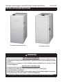 1
1
-
 2
2
-
 3
3
-
 4
4
-
 5
5
-
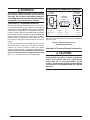 6
6
-
 7
7
-
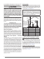 8
8
-
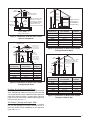 9
9
-
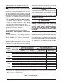 10
10
-
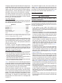 11
11
-
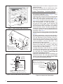 12
12
-
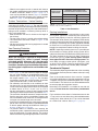 13
13
-
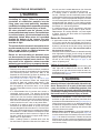 14
14
-
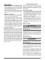 15
15
-
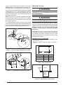 16
16
-
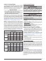 17
17
-
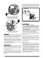 18
18
-
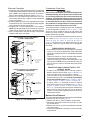 19
19
-
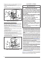 20
20
-
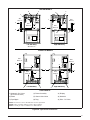 21
21
-
 22
22
-
 23
23
-
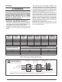 24
24
-
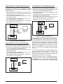 25
25
-
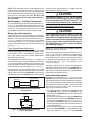 26
26
-
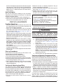 27
27
-
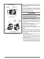 28
28
-
 29
29
-
 30
30
-
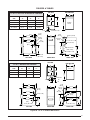 31
31
-
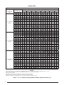 32
32
-
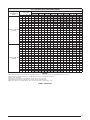 33
33
-
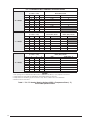 34
34
-
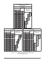 35
35
-
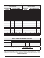 36
36
-
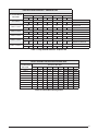 37
37
-
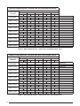 38
38
-
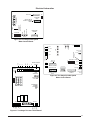 39
39
-
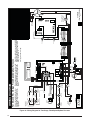 40
40
-
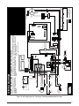 41
41
-
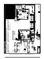 42
42
-
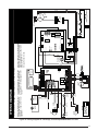 43
43
-
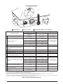 44
44
-
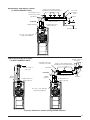 45
45
-
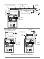 46
46
-
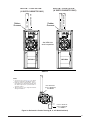 47
47
-
 48
48
-
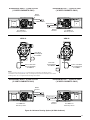 49
49
-
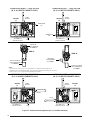 50
50
-
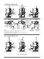 51
51
-
 52
52
-
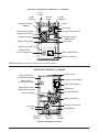 53
53
-
 54
54
-
 55
55
-
 56
56
-
 57
57
-
 58
58
-
 59
59
-
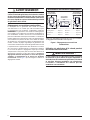 60
60
-
 61
61
-
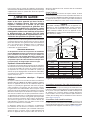 62
62
-
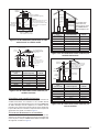 63
63
-
 64
64
-
 65
65
-
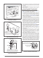 66
66
-
 67
67
-
 68
68
-
 69
69
-
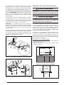 70
70
-
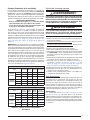 71
71
-
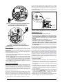 72
72
-
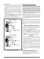 73
73
-
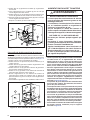 74
74
-
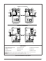 75
75
-
 76
76
-
 77
77
-
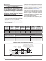 78
78
-
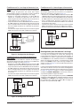 79
79
-
 80
80
-
 81
81
-
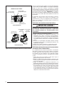 82
82
-
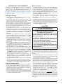 83
83
-
 84
84
-
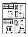 85
85
-
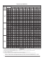 86
86
-
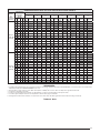 87
87
-
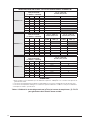 88
88
-
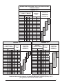 89
89
-
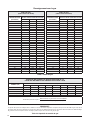 90
90
-
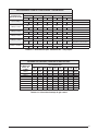 91
91
-
 92
92
-
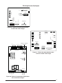 93
93
-
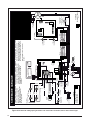 94
94
-
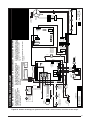 95
95
-
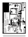 96
96
-
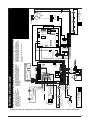 97
97
-
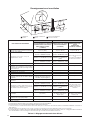 98
98
-
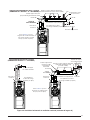 99
99
-
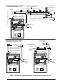 100
100
-
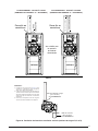 101
101
-
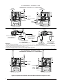 102
102
-
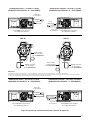 103
103
-
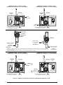 104
104
-
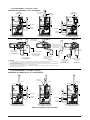 105
105
-
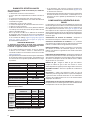 106
106
-
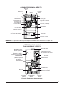 107
107
-
 108
108
-
 109
109
-
 110
110
-
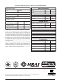 111
111
-
 112
112


Westinghouse FG7T(C,L) - VS Installation guide
- Type
- Installation guide
- This manual is also suitable for
Ask a question and I''ll find the answer in the document
Finding information in a document is now easier with AI
in other languages
Related papers
-
Broan KG7T(C,L) Installation guide
-
Broan FG7S(A,K) Installation guide
-
-
-
Broan MGC2S(A,K) Installation guide
-
Broan KG7T(E,N) Installation guide
-
-
Westinghouse MGC2S(A,K) Installation guide
-
-
Other documents
-
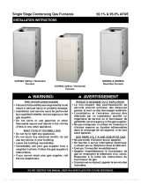 Heat Controller GUH95A Installation Instructions Manual
-
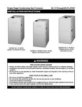 Heat Controller GUH95A Installation Instructions Manual
-
Broan FG7S(A,K) Installation guide
-
Johnson Controls TM8M/TMLM*MP User manual
-
-
York TM8T Installation guide
-
-
-
-

