Page is loading ...

Single Stage Condensing Gas Furnaces 92.1% & 95.0% AFUE
INSTALLATION INSTRUCTIONS
1
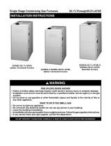
GUH92A Upflow / Horizontal
Furnace
GUH95A Upflow / Horizontal
Furnace
iJ
GDD92A & GDD95A
Downflow Furnace
A
WARNING:
FIRE OR EXPLOSION HAZARD
Failure tofollowsafetywarningsexactly
could
result in serious
injury or property damage.
Installation and service
must be performed
by a qualified installer, service
agency or the
gas supplier.
Do not store or use gasoline or other
flammable
vapors and liquids in the vicinity
of this or any other appliance.
WHAT TO DO IF YOU SMELL GAS
Do not try to
light any appliance.
Do not touch any
electrical switch; do not
use any phone in your
building.
Leave the building immediately.
Immediately call your
gas supplier from a
neighbor's phone. Follow
the gas supplier's
instructions.
If you cannot
reach your gas supplier, call
the fire department.
A AVERTISSEMENT
RISQUE D'INCENDIE OU D' EXPLOSION
Le non-respect des avertissements de
securite
pourrait entrainer des blessures
graves, la mort ou des dommages materiels.
L'installation et l'entretien doivent etre
effectues par un installateur
qualifie, un
organisme de service ou le fournisseur de
gazstaller, service agency or the gas supplier.
Ne pas entreposer ni utiliser de
('essence
ni
d'autres vapeurs ou liquides inflammables
dans le voisinage de cet appareil, ni de tout
autre appareil.
QUE FAIRE S'IL Y A UNE ODEUR DE GAZ
Ne pas tenter d'allumer aucun appareil.
Ne toucher a aucun interrupteur electrique;
n'utiliser aucun telephone dans
le batiment.
Evacuer l'immeuble immediatement.
Appeler immediatement
le fournisseur de
gaz en employant
le telephone d'un voisin.
Respecter a la lettre les instructions du
fournisseur
de gaz.
Si personne ne repond, appeler le service des
incendies.
DO NOT DESTROY THIS MANUAL. KEEP IN A SAFE PLACE FOR FUTURE REFERENCE.
PDF compression, OCR, web optimization using a watermarked evaluation copy of CVISION PDFCompressor

TABLE OF CONTENTS
IMPORTANT SAFETY INFORMATION 3
CODES & REQUIREMENTS 4
Combustion Air Quality 5
Heating Load 5
Installation in a Garage 6
Clearances to Combustible Materials 6
Operation of Furnace During Construction 6
COMBUSTION AIR & VENTING REQUIREMENTS 7
Important Information 8
Direct Vent Furnaces 8
Conventional Vent Systems - Confined Spaces 8
Air From Inside 9
Outdoor Air from a Crawl Space or
Vented Attic 9
Outdoor Air Using Vertical Ducts 9
Outdoor Air Using Horizontal Ducts 9
Air Directly Through an Exterior Wall 9
Alternate Method of Providing air from
Outside 10
Conventional Vent Systems Unconfined Spaces 10
Category IV Venting 10
Vent Pipe Material 11
Vent Pipe Length & Diameter 11
Vent Pipe Installation 12
Outdoor Terminations - Horizontal Venting 12
Outdoor Terminations - Vertical Venting 13
Vent Freezing Protection 13
Existing Installations 14
Condensate Disposal 14
CIRCULATING AIR REQUIREMENTS 14
Plenums & Air Ducts 14
Return Air Connections 15
Upflow / Horizontal Furnaces 15
Downflow Furnaces 15
Supply Air Connections 15
Acoustical Treatments 15
FURNACE INSTALLATION
General Requirements
Upflow Furnaces
Horizontal Furnaces
Special Instructions for GUH92A038A3XE
Furnaces
Downflow Furnaces
Installation on a Concrete Slab
Inducer & Venting Options
Inducer Assembly Rotation
Pressure Switch Tubing
Alternate Pressure Switch Location
Accessories
Finish Flange
Rubber Grommets
PVC Components
Typical Orientation
Alternate Orientation
Optional PVC pipe Installation
Condensate Drain Lines
Bottom Panel Removal
Alternate Bottom Panel Removal
GAS SUPPLY & PIPING
Leak Check
High-Altitude Application
Conversion to LP / Propane
ELECTRICAL WIRING
Line Voltage Wiring
Grounding
Thermostat / Low Voltage Connections
Heat Anticipator
Twinning
START-UP & ADJUSTMENTS
Pre-Start Checklist
Start-Up Procedures
Verifying & Adjusting Input Rate
Verifying & Adjusting Temperature Rise
Verifying Burner Operation
Verifying Operation of the Supply Air
Limit Switch
OPERATING SEQUENCE
Heating Cycle
Cooling Cycle
Fan Mode
16
16
16
16
16
17
17
18
18
18
18
20
20
20
21
21
21
21
21
22
22
23
23
24
27
27
28
28
29
29
29
30
30
30
30
31
31
31
31
31
31
31
2
PDF compression, OCR, web optimization using a watermarked evaluation copy of CVISION PDFCompressor

MAINTENANCE 32
FIGURES & TABLES 33
Figure 31 - Downflow Dimensions 33
Figure 32 - Upflow / Horizontal Dimensions 34
Airflow Data 35
Table 6 - GUH92A Upflow / Horiz. Furnaces 35
Table 7 - GDD92A Downflow Furnaces 36
Table 8 - GUH95A Upflow / Horiz. Furnaces 37
Table 9 - GDD95A Downflow Furnaces 38
Electrical Information 39
Figure 33 - Wiring Diagram 39
Gas Information 40
Table 10 - Gas Flow Rates 40
Table 11 - Gas Pipe Capacities 40
Table 12 - High Altitude Deration Chart for
Propane Gas 41
Table 13 - Natural Gas Heating Values 41
Table 14 - High Altitude Deration Chart for
Nat. Gas - High Heating Values 42
Table 15 - High Altitude Deration Chart for
Nat. Gas - Low Heating Values 42
Venting Information 43
Table 16 - Vent Termination Clearances 43
Venting Options for 92.1% Series 44
Figure 34 - Horiz. & Vert. Venting (92.1%) 44
Figure 35 - GUH92A Upflow Options 45
Figure 36 - GUH92A Horizontal Options
1-Pipe Furnaces 46
Figure 37 - GUH92A Horizontal Options
2-Pipe Furnaces 47
Figure 38 - GDD92A Downflow Options 48
Venting Options for 95.0% Series 49
Figure 39 - Horiz. & Vert. Venting (95.0%) 49
Figure 40 - GUH95A Upflow Options 50
Figure 41 - GUH95A Horizontal Options
1 & 2 Pipe Furnaces 51
Figure 42 - GDD95A Downflow Options 52
Troubleshooting 53
Table 17 - Control Board Fault Conditions 53
Furnace Components 53
Figure 43 - GUH92A & GUH95A
Component Locations 54
Figure 44 - GDD92A & GDD95A
Component Locations 55
INSTALLATION / PERFORMANCE CHECKLIST 56
IMPORTANT SAFETY INFORMATION
INSTALLER: Please read all instructions before servicing
this equipment. Pay attention to all safety warnings and
any other special notes highlighted in the manual. Safety
markings are used frequently throughout this manual to
designate a degree or level of seriousness and should not
be ignored. WARNING - Indicates a potentially hazardous
situation that if not avoided, could result in personal injury
or death. CAUTION - Indicates a potentially hazardous
situation that if not avoided, may result in minoror moderate
injury or property damage.
A\ WARNING:
The safety information listed in this manual
must be followed
during the installation,
service, and operation
of this unit. Unqualified
individuals should not attempt to interpret these
instructions or install this equipment. Failure
to follow safety
recommendations could result
in possible damage to the equipment, serious
personal injury
or death.
.AWARNING:
Unless otherwise
noted in these instructions,
only factory authorized
kits or accessories may
be used with or
when modifying this product.
A\ WARNING:
Improper installation, service,
adjustment,
or maintenance may cause explosion, fire,
electrical shock or other hazardous conditions
which may result in personal injury or property
damage. Unless otherwise noted
in these
instructions, only factory authorized kits or
accessories may be used with this
product.
.AWARNING:
Do not install this furnace if any
part has been
submerged under water. A flood damaged
furnace is extremely dangerous.
Attempts to
use the furnace may
result in fire or explosion. A
qualified service agency should be contacted to
inspect
the furnace and to replace any electrical
or control system parts that have been wet or
under water.
3
PDF compression, OCR, web optimization using a watermarked evaluation copy of CVISION PDFCompressor

To minimize equipment failure or personal injury, it is
essential that only qualified individuals install, service, or
maintain this equipment. If you do not posses mechanical
skills or tools, call your local dealer for assistance.
Follow all precautions in the literature, on tags, and
on labels provided with the equipment. Read and
thoroughly understand the instructions provided with
the equipment prior to performing the installation and
operational checkout of the equipment.
Use caution when handling this appliance or removing
components. Personal injury can occur from sharp metal
edges present in all sheet metal constructed equipment.
Do not store any of the following on, or in contact with,
the unit: Rags, brooms, vacuum cleaners, or other
cleaning tools, spray or aerosol cans, soap powders,
bleaches, waxes, cleaning compounds, plastics or
plastic containers, paper bags or other paper products,
gasoline, kerosene, cigarette lighter fluid, dry cleaning
fluids, paint thinners, or other volatile fluids.
The installer should become familiar with the units wiring
diagram before making any electrical connections to the
unit. See Figure 33 (page 39) or the unit wiring label.
Always reinstall the doors on the indoor blower after
servicing or cleaning/changing the filters. Do not operate
the indoor blower without all doors and covers in place.
CODES & REQUIREMENTS
A.WARNING
The information listed below
must be followed
during the installation, service, and
operation
of this furnace. Failure to follow
safety
recommendations could result in possible
damage to the equipment, serious personal
injury or death.
This furnace must be installed in accordance with
these instructions, all applicable local building codes
and the current revision of the National Fuel Gas Code
(NFPA54/ANSI Z223.1) orthe Natural Gas and Propane
Installation Code, CAN/CGA B149.1.
Use only with type of gas approved for this furnace.
Refer to the furnace rating plate.
Install this furnace only in a location and position as
specified on page 6.
Provide adequate combustion and ventilation air to the
furnace space as specified on pages 7 - 10.
Provide adequate clearances around the vent air intake
terminal as shown in Figures 7 - 10 (pages 12-13).
Combustion products must be discharged outdoors.
Connect this furnace to an approved vent system only,
as specified on pages 10 - 14.
Never test for gas leaks with an open flame. Use
a commercially available soap solution to check all
connections. See pages 23 - 24.
4
This furnace is designed to operate with a maximum
external pressure rise of 0.5 inches of water column.
Consult Tables 6 - 9 (pages 35 & 38), and the rating
plate for the proper circulating air flow and temperature
rise. It is important that the duct system be designed
to provide the correct flow rates and external pressure
rise. An improperly designed duct system can result in
nuisance shutdowns, and comfort or noise issues.
When supply ducts carry air circulated by the furnace
to areas outside the space containing the furnace, the
return air shall also be handled by duct(s) sealed to
the furnace casing and terminating in the conditioned
space. See pages 14 & 15.
A gas-fired furnace for installation in a residential garage
must be installed as specified on page 6.
This furnace may be used for temporary heating of
buildings or structures under construction. See the
guidelines listed on page 6.
This furnace is not approved for installation in mobile
homes. Installing this furnace in a mobile home could
cause fire, property damage, and/or personal injury.
The Commonwealth of Massachusetts requires
compliance with regulation 248 CMR 4.00 and 5.00 for
installation of through -the-wall vented gas appliances
as follows:
1. For direct-vent appliances, mechanical-vent heating
appliances or domestic hot water equipment, where the
bottom of the vent terminal and the air intake is installed
below four feet above grade the following requirements
must be satisfied:
a.) A carbon monoxide (CO) detector and alarm shall
be placed on each floor level where there are
bedrooms. The detector shall comply with NFPA
720 (2005 Edition) and be mounted in the living
area outside the bedroom(s).
b.) A (CO) detector shall be located in the room that
houses the appliance or equipment and shall:
Be powered by the same electrical circuit as the
appliance or equipment. Only one service switch
shall power the appliance and the (CO) detector;
Have battery back-up power;
Meet ANSI/UL 2034 Standards and comply with
NFPA 720 (2005 Edition); and Approved and listed
by a Nationally Recognized Testing Laboratory as
recognized under 527 CMR.
c.) A Product-approved vent terminal must be used,
and if applicable, a product-approved air intake must
be used. Installation shall be in strict compliance
with the manufacturer's instructions. A copy of
the installation instructions shall remain with the
appliance or equipment at the completion of the
installation.
d.) A metal or plastic identification plate shall be
mounted at the exterior of the building, four feet
directly above the location of vent terminal. The
plate shall be of sufficient size, easily read from
a distance of eight feet away, and read "Gas Vent
Directly Below".
PDF compression, OCR, web optimization using a watermarked evaluation copy of CVISION PDFCompressor

2. For direct-vent appliances, mechanical-vent heating
appliances or domestic hot water equipment where the
bottom of the vent terminal and the air intake is installed
above four feet above grade the following requirements
must be satisfied:
a.) A (CO) detector and alarm shall be placed on each
floor level where there are bedrooms. The detector
shall comply with NFPA 720 (2005 Edition) and be
mounted in the living area outside the bedroom(s).
b.) The (CO) detector shall:
Be located in the room that houses the appliance
or equipment;
Be hard-wired or battery powered or both.
Shall comply with NFPA 720 (2005 Edition).
c.) A product-approved vent terminal must be used,
and if applicable, a product-approved air intake must
be used. Installation shall be in strict compliance
with the manufacturer's instructions. A copy of
the installation instructions shall remain with the
appliance or equipment at the completion of the
installation.
The information listed below is for reference purposes only
and does not necessarily have jurisdiction over local or state
codes. Always consult with local authorities before installing
any gas appliance.
Combustion & Ventilation Air
US: National Fuel Gas Code (NFGC), Air for Combustion
and Ventilation
CANADA: Natural Gas and Propane Installation Codes
(NSCNGPIC), Venting Systems and Air Supply for
Appliances
Duct Systems
US and CANADA: Air Conditioning Contractors Association
(ACCA) Manual D, Sheet Metal and Air Conditioning
Contractors National Association (SMACNA), or American
Society of Heating, Refrigeration, and Air Conditioning
Engineers (ASHRAE) Fundamentals Handbook
Electrical Connections
US: National Electrical Code (NEC) ANSI/NFPA 70
CANADA: Canadian Electrical Code CSA C22.1
Gas Piping & Gas Pipe Pressure Testing
US: NFGC and National Plumbing Codes
CANADA: NSCNGPIC
General Installation
US: Current edition of the NFGC and the NFPA 90B. For
copies, contact the National Fire Protection Association Inc.,
Batterymarch Park, Quincy, MA 02269; or American Gas
Association, 400 N. Capitol, N.W., Washington DC 20001
or www.NFPA.org
CANADA: NSCNGPIC. For a copy, contact Standard Sales,
CSA International, 178 Rexdale Boulevard, Etobicoke
(Toronto), Ontario, M9W 1 R3 Canada
Safety
US: (NFGC) NFPA54-1999/ANSI Z223.1 andthe Installation
Standards, Warm Air Heating and Air Conditioning Systems
ANSI/NFPA 90B.
CANADA: CAN/CGA-B149.1 and .2-M00 National Standard
of Canada. (NSCNGPIC)
Combustion
Air Quality
CAUTION:
Combustion air must
not be drawn from a
corrosive atmosphere.
To maximize heat exchanger life, the combustion air
must be free of chemicals that can form corrosive acidic
compounds in the combustion gases. The recommended
source of combustion air is to use outdoor air. However,
the use of indoor air in most applications is acceptable
except as listed:
If the furnace is installed as a single pipe installation
in a confined space, it is required that the necessary
combustion air come from the outdoors by way of attic,
crawl space, air duct, or direct opening. For Installations
in confined spaces, see pages 8 - 10 for combustion
air requirements.
Installations in these locations may require outdoor air
for combustion, due to chemical exposures:
Commercial buildings
Buildings with indoor pools
Furnaces installed in laundry rooms
Furnaces installed in hobby or craft rooms
Furnaces installed near chemical storage areas
Exposure to the following substances in the combustion
air supply may require outdoor air for combustion:
Permanent wave solutions
Chlorinated waxes and cleaners
Chlorine based swimming pool chemicals
Water softening chemicals
De-icing salts or chemicals
Carbon Tetrachloride
Halogen type refrigerants
Cleaning solvents (perchloroethylene)
Printing inks, paint removers, varnishes, etc.
Hydrochloric Acid
Cements and glues
Antistatic fabric softeners
Masonry acid washing materials
Heating Load
This furnace should be sized to provide the design heating
load requirement. Heating load estimates can be made
using approved methods available from Air Conditioning
Contractors of America (Manual J); American Society of
Heating, Refrigerating, and Air Conditioning Engineers;
or other approved engineering methods. Excessive
oversizing of the furnace could cause the furnace
and/or vent to fail prematurely.
The ductworkshould be appropriately sized to the capacity
of the furnace to ensure its proper airflow rating. For
installations above 2,000 ft., the furnace should have a
sea level input rating large enough that it will meet the
heating load after deration for altitude.
5
PDF compression, OCR, web optimization using a watermarked evaluation copy of CVISION PDFCompressor

Installation in a Garage
Operation of
Furnace During Construction
WARNING:
Do not place combustible material
on or against
the furnace cabinet or within 6 inches of the
vent pipe. Do not place
combustible materials,
including gasoline or any other flammable
vapors and liquids, in the vicinity of the furnace.
This gas-fired furnace may be installed in a residential
garage with the provision that the burners and igniter
are located no less than 18 inches (457mm) above the
floor. The furnace must be located or protected to prevent
physical damage by vehicles.
Clearances to Combustible Materials
This furnace is Design Certified in the U.S. and Canada
by CSA International for the minimum clearances to
combustible materials. NOTE: The furnace is listed for
installation on combustible or non-combustible flooring.
However, wood is the only combustible flooring allowed
for installation. Downflow models must use the appropriate
subase kit when installing over a wood floor. To obtain
model number and specific clearance information, refer
to the furnace rating plate, located inside of the furnace
cabinet.
Access for positioning and servicing the unit must be
considered when locating unit. The need to provide
clearance for access to panels or doors may require
clearance distances over and above the requirements.
Allow 24 inches minimum clearance from the front of
the unit. However 36 inches is strongly recommended.
See Figure 1 for minimum clearance requirements.
CLEARANCES TO COMBUSTIBLE MATERIALS
UPFLOW DOWNFLOW
APPLICATIONS APPLICATIONS
BACK
TOP
HORIZONTAL
APPLICATIONS
a
U-1
SID E
FRONT
SIDE
BACK
TOP
00
Lu I
7.) I
O I
E I
1-I
E
Left Side 0 Inches Top 0 Inches
Right Side 0 Inches Front t4 Inches
Vent 0 Inches Back 0 Inches
fAllow 24 in. minimum clearance for servicing. Recommended
clearance is 36 in.
6
Figure 1. Minimum Clearances to
Combustible Materials
CAUTION:
Failure to follow these instructions will void the
factory warranty and may significantly
reduce
the life or the performance
of the furnace, and/
or result in other unsafe conditions. It is the
responsibility of the installing contractor to
insure these provisions
are met.
Operating gas furnaces in construction environments can
cause a variety of problems with the furnace. Proper use
of commercial portable space heating equipment during
construction is recommended. This gas furnace may be
used during construction if it is not in violation of any
applicable codes and the following criteria are met:
The installation must meet all applicable codes. The
furnace must be permanently installed according to the
instructions supplied with the furnace including electrical
supply, gas supply, duct work and venting. The furnace
must be controlled by a thermostat properly installed
according to the instructions supplied with the furnace
and thermostat. The installation must include a properly
installed filter in the return air system with no by-pass
air. The filter must be inspected frequently and replaced
when necessary.
Combustion air must be supplied from outside the
structure and located such that dust and gases
from construction activity are not introduced into the
combustion system.
Provisions must be made to insure that condensate
does not freeze in the furnace or condensate drain lines
during operation and during idle times; for example,
overnight if turned off.
Before occupying the structure: The filter must be
replaced or cleaned, the duct work must be inspected
and cleaned of any construction debris, and the furnace
must be cleaned and/or repaired if found to be dirty,
damaged, or malfunctioning in any way by a qualified
HVAC technician. The furnace shall be inspected and
approved by applicable local authority even if this
requires redundant inspections.
Serial numbers for furnaces used during construction
must be submitted in writing (fax and email also
acceptable). This information will be used to track the
long-term affects of the use during construction on
furnaces. Proof of this submittal shall be available for
the final inspection of the furnace prior to occupancy.
This furnace is designed to operate with return air
temperatures in ranges normally found in occupied
residences, including setbacks. Minimum continuous
return temperature must not be below 60° F (15° C).
Occasionally a temporary return temperature of 55° F
(12° C) is acceptable. However, operation with a return
temperature below 55° F (12° C) is not allowed.
PDF compression, OCR, web optimization using a watermarked evaluation copy of CVISION PDFCompressor

COMBUSTION AIR & VENTING REQUIREMENTS
WARNING:
CARBON MONOXIDE POISONING HAZARD
Failure to follow the steps
outlined below
for each appliance connected
to the venting
system being placed into operation could
result in carbon
monoxide poisoning
or death.
The following steps shall be followed with
each individual appliance connected to the
venting system being placed
in operation,
while all other appliances
connected to the
venting system are not in operation:
1. Seal any unused openings
in the venting system.
2. Inspect the venting system for proper
size and
horizontal pitch, as required in the National Fuel
Gas Code, ANSI Z223.1INFPA 54 or the CSA
B149.1, Natural Gas and Propane Installation
Codes and these instructions. Determine that
there is no blockage
or restriction, leakage,
corrosion and other deficiencies which could
cause an unsafe condition.
3. As far as practical, close all building doors and
windows
and all doors between the space in
which the appliance(s) connected to the venting
system are located and other spaces of the
building.
4. Close
fireplace dampers.
5. Turn on clothes dryers and any appliance not
connected to the
venting system. Turn on any
exhaust fans, such as range hoods and bathroom
exhausts, so they are
operating at maximum
speed. Do not operate a summer exhaust
fan.
6. Follow the lighting instructions. Place the
appliance being inspected
into operation.
Adjust the thermostat
so appliance is operating
continuously.
7. Test for spillage from
draft hood equipped
appliances at the draft
hood relief opening after
5 minutes of main burner
operation. Use the
flame of a match
or candle.
8. If improper venting is observed
during any of
the above
tests, the venting system must be
corrected in accordance
with the National Fuel
Gas Code, ANSI Z223.1INFPA 54 and/or CSA
B149.1, Natural Gas and Propane Installation
Codes.
9. After it has been determined that each
appliance
connected to the
venting system properly vents
when tested as outlined above, return doors,
windows, exhaust
fans, fireplace dampers and
any other
gas-fired burning appliance to their
previous
conditions of use.
AVERTISSEMENT:
RISQUE
D'EMPOISONNEMENT AU
MONOXYDE DE CARBONED
Le non-respect des consignes suivantes portant
sur chacun des appareils raccordes au systeme
d'evacuation mis en service pourrait entrainer
l'empoisennement au monoxyde de carbone ou
la mort. Les consignes suivantes doivent etre
observees pour chaque apparell raccorde au
systeme d'evacuation mis en service si les autres
appareils raccordes au systeme ne sont pas en
service:
1. Sceller toute ouverture non utilisee de la systeme
d'evacuation;
2. S'assurerque la systemed'evacuation presentedes
dimensions et une pente horizontale conformes a la
norme ANSI Z223.1/NFPA 54, intitulee National Fuel
Gas Code ou aux codes d'installation CSA-B149.1,
ainsi qu'aux presentes instructions. S'assurerque la
systemed'evacuation n'est pas bloquee, restreinte,
corrodee, qu'elle ne fuit pas et qu'elle ne presente
aucun autre defaut potentiellement dangereux;
3. Dans la mesure du possible, fermertoutes les portes
et fenetres du batiment, et toutes les portes entre la
piece ou se trouve l'appareil raccorde a la systeme
d'evacuation et les autres pieces du batiment.
4. Fermer les registres des foyers;
5. Mettre en service les secheuses et tout autre apparel!
qui n'est pas raccorde a la systeme d'evacuation.
Faire fonctionner a regime maximal tout ventilateur
d'evacuation, tel que les hottes de cuisiniere et les
ventilateurs de salles de bains. Ne pas mettre en
service les ventilateurs d'ete.
6. Respecter les instructions d'allumage. Mettre en
service l'appareil a l'essai. Regler le thermostat
de maniere a ce que l'appareil fonctionne sans
interruption;
7. Verifier s'il y a debordement a l'orifice d'evacuation
du coupe tirage des appareils dotes d'un coupe
tirage 5 minutes apres l'allumage du brilleur
principal. Utiliser la flamme d'une allumette ou
d'une chandelle.
8. Si l'on constate, au cours de l'un des essais qui
precedent, que ('evacuation est deficiente, corriger
le systeme d'evacuation conformement a la norm
ANSI Z223.1/NFPA 54, National Fuel Gas Code, et
(ou) aux codes d'installation CSA B149.1.
9. Apres avoir determine que tous les appareils
raccordes a la systeme d'evacuation evacuent
correctement tel que prescrit ci-dessus, rouvrir les
portes et les fenetres et remettre les ventilateurs
d'evacuation, les registres de foyers et tout
autre apparell fonctionnant au gaz a leur etat de
fonctionnement initial.
7
PDF compression, OCR, web optimization using a watermarked evaluation copy of CVISION PDFCompressor

Important Information
This furnace must be vented in compliance with
the current revision of the National Fuel Gas Code
(ANSI-Z223.1/NFPA54). Instructions for determi ning
the adequacy of an installation can be found in the
current revision of the NFGC (ANSI Z223.1 /NFPA54).
Consult local codes for special requirements. These
requirements are for US installations as found in
the NFGC.
Furnace installation using methods otherthan those
described in the following sections must comply
with the National Fuel Gas Code (NFGC) and all
applicable local codes.
Requirements in Canada (B149.1) are structured
differently. In Canada, venting shall conform to the
requirements of the current (CAN/CGA B149.1 or .2)
installation codes. Consult local codes for special
requirements.
Provisions must be made during the installation
of this furnace that provide an adequate supply of
air for combustion. The combustion air from the
outside needs to be clear of chemicals that can
cause corrosion. The inlet pipe should not be placed
near corrosive chemicals such as those listed on
page 5.
WARNING:
Upon completion
of the furnace installation,
carefully inspect the entire flue system both
inside and outside the furnace to assure it is
properly sealed. Leaks in the flue system can
result in serious
personal injury or death due
to exposure of flue products, including carbon
monoxide.
WARNING:
This furnace must not be vented with other
appliances,
even if that appliance is of the
condensing type.
Common venting can result
in severe corrosion
of other appliances or their
venting and can allow
combustion gases to
escape through such appliances or
vents. Do
not vent the furnace to a fireplace
chimney or
building
chase.
This condensing furnace is certified for installation either as
a Direct Vent (2-pipe) or Conventional (1-pipe) appliance.
Direct Vent appliances draw combustion air from the
outdoors and vent combustion products back outside.
Installation with air taken from around the furnace is often
referred to as Conventional installation - i.e. only the vent
(exhaust) pipe is provided.
8
Another important consideration when selecting one or
two pipe installation is the quality of the Indoor air which
can sometimes be contaminated with various household
chemicals . These chemicals can cause severe corrosion
in the furnace combustion system. A 2-pipe installation
has the additional advantage that it isolates the system
from the effects of negative pressure in the house.
CAUTION:
Exhaust fans, clothes
dryers, fireplaces and
other appliances that force
air from the house
to the outdoors can create a negative pressure
inside the house, resulting in improper furnace
operation or unsafe conditions such
as flame roll
out. It is imperative that sufficient air exchange
with the outdoors is provided
to prevent
depressurization.
Additional information about
how to test for negative
pressure problems can
be found in
the NFGC.
Air openings on top of the furnace and openings in closet
doors or walls must never be restricted. If the furnace is
operated without adequate air for combustion, the flame
roll-out switch will open, turning off the gas supply to the
burners. This safety device is a manually reset switch.
DO NOT install jumper wires across these switches
to defeat their function or reset a switch without
identifying and correcting the fault condition. If a
switch must be replaced, use only the correct sized part
specified in the Replacement Parts List provided online.
Direct Vent Furnaces
Direct Vent (2-pipe) furnaces draw combustion air directly
from the outdoors and then vent the combustion products
back outside, isolating the entire system from the indoor
space. It is important to make sure that the whole system
is sealed and clearances to combustibles are maintained
regardless of the installation being in a confined or
unconfined space.
Conventional Vent Systems -
Confined
Spaces
A confined space is an area with volume less than 50
cubic feet per 1,000 Btuh of the combined input rates of
all appliances drawing combustion air from that space.
Furnace closets, small equipment rooms and garages are
confined spaces. Furnaces installed in a confined space
which supply heated air to areas outside the space must
draw return air from outside the space and must have the
return air ducts tightly sealed to the furnace. Ducts must
have cross - sectional area at least as large as the free area
of their respective openings to the furnace space. Attics
or crawl spaces must connect freely with the outdoors if
they are the source of air for combustion and ventilation.
The required sizing of these openings is determined by
whether inside or outside air is used to support combustion,
the method by which the air is brought to the space, and
PDF compression, OCR, web optimization using a watermarked evaluation copy of CVISION PDFCompressor

by the total input rate of all appliances in the space. In
all cases, the minimum dimension of any combustion air
opening is 3 inches.
Air From Inside
If combustion air is taken from the heated space, the two
openings must each have a free area of at least one square
inch per 1,000 Btuh of total input of all appliances in the
confined space, but not less than 100 square inches of
free area. See example and Figure 2.
Example:
If the combined input rate of all appliances is less
than or equal to 100,000 Btuh, each opening must
have a free area of at least 100 square inches. If the
combined input rate of all appliances is 120,000 Btuh,
each opening must have a free area of at least 120
square inches.
Vent or
Chimney
1
NOTES:
Each opening must be
at least 100 sq. in. or NI
r
12" Max.
See
-f-
Notes
Max. Max.
1 sq. in. per 1,000 Btuh
of total input rating,
whichever is greater.
Openings must start at
no more than 12 inches
from
the enclos
the top and bottom
of
iii
Water
Heater
/
Furnace
See
Notes-'
Total Input Rating
(Btuh)
Minimum Free Area
(Each Opening)
Round Duct
Diameter
40,000 100 sq. In 12 inches
60,000 100 sq. In 12 inches
80,000 100 sq. In 12 inches
100,000 100 sq. In 12 inches
120,000 120 sq. In 13 inches
140,000 140 sq. In 14 inches
160,000 160 sq. In 15 inches
Figure 2. Combustion Air Drawn from Inside
Outdoor Air from a Crawl Space or Vented
Attic
When the openings can freely exchange air with the
outdoors, each opening shall have a minimum free area
of 1 square inch per 4,000 Btuh of total appliance input.
The openings shall exchange directly, or by ducts, with
the outdoor spaces (crawl or attic) that freely exchange
with the outdoors (Figure 3).
Outdoor Air Using Vertical Ducts
If combustion air is taken from outdoors through vertical
ducts, the openings and ducts must have a minimum free
area of one square inch per 4,000 Btuh of total appliance
input (Figure 4).
Vent or
Chimney
Ventilation Louvers
(each end of attic)
Alternate
Air Inlet
NOTE: Air openings shall
each have a free area of
not less than one square
inch per 4,000 Btuh of the
total input rating of all
equipment in the enclosure.
Ventilation Louvers For
Unheated Crawl Space
Figure 3. Combustion Air Drawn from a Crawl
Space or Vented Attic
Ventilation
at each
Vent or
Chimney
I
Louvers
end of attic
Air Duct must be
at least 1 sq. in.
per 4,000 Btuh of
Attic
total input rating.
Insulation
i
-4111111111111511=1 ME
Ducts must
extend above
attic insulation.
Air Duct must be
Water
Heater
Furnace
/
7/
at least 1 sq. in.
per 4,000 Btuh of
total input rating.
.. II
4-12" Max
Total Input Rating
(Btuh)
Minimum Free Area
(Each Opening)
Round Duct
Diameter
40,000 10 sq. In 4 inches
60,000 15 sq. In 5 inches
80,000 20 sq. In 5 inches
100,000 25 sq. In 6 inches
120,000 30 sq. In 6 inches
140,000 35 sq. In 7 inches
160,000 40 sq. In 8 inches
Figure 4. Combustion Air Drawn from Outside
Through Vertical Ducts
Outdoor Air Using Horizontal Ducts
If combustion air is taken from outdoors through horizontal
ducts, the openings and ducts must have a minimum free
area of one square inch per 2,000 Btuh of total appliance
input (Figure 5, page 10). Ducts must have cross - sectional
area at least as large as the free area of their respective
openings to the furnace space.
Air Directly Through An Exterior Wall
If combustion air is provided directly through an exterior
wall, the two openings must each have free area of at
least one square inch per 4,000 Btuh of total appliance
input (Figure 6, page 10).
9
PDF compression, OCR, web optimization using a watermarked evaluation copy of CVISION PDFCompressor

Vent or
Chimney
Lomont
Water
Heater
1
Furnace
7
Air Ducts must be
at least 1 sq. in.
per 2,000 Btuh of
total input rating.
,
1.1
Total Input Rating
(Btuh)
Minimum Free Area
(Each Opening)
Round Duct
Diameter
40,000 20 sq. In 5 inches
60,000 30 sq. In 6 inches
80,000 40 sq. In 7 inches
100,000 50 sq. In 8 inches
120,000 60 sq. In 9 inches
140,000 70 sq. In 10 inches
160,000 80 sq. In 10 inches
Figure 5. Combustion Air Drawn from Outside
Through Horizontal Ducts
Vent or
Chimney
I
NOTE: Each opening to outside
must be at least 1 sq. in. per
4,000 Btuh of total input rating.
See
Note
See
Note
12" Max.
v
t.
%
o
i
Water
Heater
I
Furnace
Total Input Rating
(Btuh)
Minimum Free Area
(Each Opening)
Round Duct
Diameter
40,000 10 sq. In 4 inches
60,000 15 sq. In 5 inches
80,000 20 sq. In 5 inches
100,000 25 sq. In 6 inches
120,000 30 sq. In 6 inches
140,000 35 sq. In 7 inches
160,000 40 sq. In 8 inches
Figure 6. Combustion Air Drawn from Outside
Through an Exterior Wall
Example:
A space with a water heater rated at 45,000 Btuh
input and a furnace rated at 75,000 Btuh requires a
volume of 6,000 cubic feet [50 x (45 + 75) = 6,000] to
be considered unconfined. If the space has an 8 foot
ceiling, the floor area of the space must be 750 sq. ft.
(6,000 / 8 = 750).
10
Alternate Method of Providing Air from
Outside
If acceptable under local Codes, it is permitted to provide
outside air using one opening (See NFGC). Generally,
confined spaces must have two openings in the space for
combustion air. One opening must be within 12 inches of
the ceiling, and the other must be within 12 inches of the
floor. However, an alternative method recently adopted by
the NFGC uses one opening within 12 inches of the top
of the space. This method may be used if it is acceptable
to the local codes.
The following conditions must be met:
1. The opening must start within 12" of the top of the
structure and connect with the out of doors through
vertical or horizontal ducts or be ducted to a crawl or
attic space that connects with the out of doors.
2. The opening must have a minimum free area of 1 sq.
in. per 3,000 Btu per hour of the total input rating of all
equipment located in the enclosure.
3. The free area must not be less than the sum of all the
areas of the vent connectors in the enclosure.
Conventional Vent Systems - Unconfined
Spaces
An unconfined space is an area including all rooms not
separated by doors with a volume greater than 50 cubic
feet per 1,000 Btuh of the combined input rates of all
appliances which draw combustion air from that space.
In general, a furnace installed in an unconfined space will
not require outside air for combustion. However, in homes
built for energy efficiency (low air change rates), it may
be necessary to provide outside air to ensure adequate
combustion and venting, even though the furnace is located
in an unconfined space. See example below.
Category
IV Venting
.AWARNING
Upon completion
of the furnace installation,
carefully inspect the entire flue system both
inside and outside the furnace to assure it is
properly sealed. Leaks in the flue system can
result in serious
personal injury or death due
to exposure of flue products, including carbon
monoxide.
This furnace is classified as a "Category IV" appliance,
which requires special venting materials and installation
procedures. This section specifies installation requirements
for Conventional (1-pipe) and Direct Vent (2-pipe) piping.
For 1- pipe installations, install vent piping as described in
this section and provide air for combustion and ventilation
according to pages 7 -10. Table 1 (page 11) contains the
length of vent and combustion air piping for either type
of installation.
PDF compression, OCR, web optimization using a watermarked evaluation copy of CVISION PDFCompressor

Category IV appliances operate with positive vent pressure
and therefore require vent systems which are thoroughly
sealed. They also produce liquid condensate, which is
slightly acidic and can cause severe corrosion of ordinary
venting materials. Furnace operation can be adversely
affected by restrictive vent and combustion air piping.
The inducer assembly on this furnace can be rotated to
vent the flue products out of the top, left or right side. This
increases the flexibility of which direction the vent pipe
can exit the furnace.
Vent Pipe Material
Vent and combustion air pipe and fittings must be one of
the following materials in the list and must conform to the
indicated ANSI/ASTM standards. Cement must conform
to ASTM Standard D2564 for PVC and Standard D2235
for ABS. PVC primer must meet standard ASTM F656.
When joining PVC piping to ABS, use PVC solvent cement.
(See procedure specified in ASTM Standard D3138).
In Canada, all plastic vent pipes and fittings including
any cement, cleaners, or primers must be certified as a
system to ULC S636. However this requirement does not
apply to the finish flanges or piping internal to the furnace.
Materials Standards
SCHEDULE 40PVC D1785
PVC-DWV D2665
SDR-21 & SDR-26 D2241
ABS-DWV D2661
SCHEDULE 40 ABS F628
FOAM / CELLULAR CORE PVC F891
Vent Pipe Length & Diameter
In order for the furnace to operate properly, the combustion
air and vent piping must not be excessively restrictive.
The venting system should be designed to have the
minimum number of elbows or turns.
All horizontal runs must slope upwards from the furnace
at 1/4 inch minimum per running foot of vent.
Transition to the final vent diameter should be done as
close to the furnace outlet as practical.
Always use the same size or a larger pipe for combustion
air that is used for the exhaust vent.
Table 1 indicates the maximum allowable pipe length for
a furnace of known input rate, when installed with piping
of selected diameter and number of elbows. To use the
table, the furnace input rate, the centerline length and the
number of elbows on each pipe must be known.
When estimating the length of vent runs, consideration
must be made to the effect of elbows and other fittings.
This is conveniently handled using the idea of "equivalent
length". This means the fittings are assigned a linear
length that accounts for the pressure drop they will cause.
For example: a 2" diameter, long radius elbow is worth
the equivalent of 2.5 feet of linear run. A 90 degree tee
is worth 7 ft.
The equivalent lenghts of tees and various elbows are
listed in Table 1. Measure the linear length of your vent run
and then add in the equivalent length of each fitting. The
total length, including the equivalent fitting lengths, must
be less than the maximum length specified in the table.
Condensing furnace combustion products have very little
buoyancy, so Table 1 is to be used without consideration
of any vertical rise in the piping.
FURNACE
MODELS
(BTU)
FURNACE
INSTALLATION
SINGLE VENT PIPE LENGTH (FT.)
with 1 long radius elbowt
DUAL VENT PIPE LENGTH (FT.)
with 1 long radius elbow on each pipet
OUTLET
2" Diameter
OUTLET
3" Diameter
INLET / OUTLET
2" Diameter
INLET / OUTLET
3" Diameter
38,000 Upflow 50 70 50 70
54,000
Upflow 70 90 70 90
Downflow 70 90 70 90
72,000
Upflow 50 90 50 90
Downflow 50 90 50 90
90,000
Upflow 60 90 60 90
Downflow 60 90 60 90
108,000 Upflow N/A 90 N/A 90
118,000 Downflow N/A 90 N/A 90
120,000
Upflow N/A 90 N/A 90
Downflow N/A 90 N/A 90
t NOTES:
1 Subtract 2.5 ft. for each additional 2 inch long radius elbow, 5 ft. for each additional 2 inch short radius elbow, 3.5 ft. for each additional 3
inch long radius elbow, and 7 ft. for each additional 3 inch short radius elbow. Subtract 5 ft for each 2" tee and 8 ft for each 3" tee.
2. Two 45 degree elbows are equivalent to one 90 degree elbow.
3. This table applies for elevations from sea level to 2,000 ft. For higher elevations, decrease pipe lengths by 8% per 1,000 ft of altitude.
4. A long radius elbow's centerline radius is equal to or greater than 1.5 times the vent diameter.
Table 1. Vent Pipe Lengths
11
PDF compression, OCR, web optimization using a watermarked evaluation copy of CVISION PDFCompressor

Vent Pipe Installation
A\ CAUTION:
Combustion air must
not be drawn from a
corrosive atmosphere.
This furnace has been certified for installation with zero
clearance between vent piping and combustible surfaces.
However, it is good practice to allow space for convenience
in installation and service.
In the absence of local codes, the location of any
combustion air inlet relative to any vent terminal must
be at least 8 inches. This includes installations involving
more than one furnace.
The quality of outdoor air must also be considered. Be
sure that the combustion air intake is not located near
a source of solvent fumes or other chemicals which
can cause corrosion of the furnace combustion system.
(See page 5 for a sample list of substances).
Route piping as direct as possible between the furnace
and the outdoors. Longer vent runs require larger
diameters. Vent piping must be sloped upwards 1/4"
per foot in the direction from the furnace to the terminal.
This ensures that any condensate flows back to the
condensate disposal system.
If a Direct Vent (2-pipe) system is used, the combustion
air intake and the vent exhaust must be located in the
same atmospheric pressure zone. This means both
pipes must exit the building through the same portion
of exterior wall or roof as shown in Figure 34 (page 44)
or Figure 39 (page 49).
Piping must be mechanically supported so that its weight
does not bear on the furnace. Pipe supports must be
installed a minimum of every five feet along the vent run
to ensure no displacement after installation. Supports
may be at shorter intervals if necessary to ensure that
there are no sagging sections that can trap condensate.
It is recommended to install couplings along the vent
pipe, on either side of the exterior wall (Figures 34 or
39). These couplings may be required by local code.
If breakable connections are required in the combustion
air inlet pipe (if present) and exhaust vent piping, then
straight neoprene couplings for 2" or 3" piping with
hose clamps can be used. These couplings can be
ordered through your local furnace distributor. To install
a coupling:
1. Slide the rubber coupling over the end of the pipe that
is attached to the furnace and secure it with one of the
hose clamps.
2. Slide the other end of the rubber coupling onto the other
pipe from the vent.
3. Secure the coupling with the second hose clamp,
ensuring that the connection is tight and leak free.
12
Outdoor Terminations - Horizontal Venting
Vent and combustion air intake terminations shall be
installed as shown in Figures 7 & 8 and in accordance
with these instructions:
Vent termination clearances must be consistent with the
NFGC, ANSI 2223.1/NFPA 54 and/or the CSA B149.1,
Natural Gas and Propane Installation Code. Table 16
(page 43) lists the necessary distances from the vent
termination to windows and building air intakes.
Vent and combustion air intake terminations must
be located to ensure proper furnace operation and
conformance to applicable codes. A vent terminal
must be located at least 3 feet above any forced air
inlet located within 10 feet. This does not apply to the
combustion air inlet of a directvent (two pipe) appliance.
In Canada, CSA B149.1 takes precedence over these
instructions. See Table 16.
All minimum clearances must be maintained to protect
building materials from degradation by flue gases. ee
(Figure 8).
Figure 7. Inlet & Exhaust Pipe Clearances
Mechanical draft
vent terminal
NOTES:
1. All dimensions shown are
minimum requirements.
2. Exterior vent terminations must
be located at least 12" above the
maximum expected snow level.
10
e
Forced air inlet
Direct vent
terminal - more
than 50,000 Btuh
Figure 8. Vent Locations
PDF compression, OCR, web optimization using a watermarked evaluation copy of CVISION PDFCompressor

For optimal performance, vent the furnace through a
wall that experiences the least exposure to winter winds.
The vent termination shall be located at least 3 ft.
horizontally from any electric meter, gas meter, regulator
and any relief equipment. These distances apply ONLY
to U.S. installations. In Canada, CSA B149.1 takes
precedence over these instructions.
Do not install the vent terminal such that exhaust is
directed into window wells, stairwells, under decks
or into alcoves or similar recessed areas, and do not
terminate above any public walkways.
If venting horizontally, a side wall vent kit is available
according to the pipe diameter size of the installation.
For 2 inch pipe use side wall vent kit #904617, and
for 3 inch pipe use kit #904347. Please follow the
instructions provided with the kit.
Concentric vent termination kits are available for use
with these furnaces. For 2 Inch pipe use kit #904952
and or 3 inch pipe use kit # 904953. Please follow the
instructions provided with the kit.
When the vent pipe must exit an exterior wall close to
the grade or expected snow level where it is not possible
to obtain clearances shown in Figure 7, a riser may be
provided as shown in Figure 9. Insulation is required
to prevent freezing of this section of pipe. See Table 3
(page 14) for vent freezing protection.
Support
19" Max.
See Note)
12" Above
Maximum
Expected
Snow Level
Outside
-.-
Wall
1/2"
Armaflex
Insulation or
Equivalent
(if required)
NOTE: Vent Configuration to ProVde
12" Minimum height above Snow Level.
Figure 9. Alternate Horizontal Vent Installation
Elbows on the combustion air
inlet must be positioned pointing
away from the exhaust vent.
12" Above Maximum
Expected Snow Leve
(Both pipes)
Plumbing Vent Roof Boot
(Both Pipes)
Figure 10. Vertical Vent Termination
Outdoor Terminations - Vertical Venting
Termination spacing requirements from the roof and from
each other are shown in Figure 10. The roof penetration
must be properly flashed and waterproofed with a plumbing
roof boot or equivalent flashing. Vent and combustion air
piping may be installed in an existing chimney which is
not in use provided that:
Both the exhaust vent and air intake run the length of
the chimney.
The top of the chimney is sealed and weatherproofed.
The termination clearances shown in Figure 10 are
maintained.
No other gas fired or fuel-burning equipment is vented
through the chimney.
Vent Freezing Protection
A\ CAUTION:
When the vent pipe is exposed
to temperatures
below freezing (i.e., when it passes through
unheated spaces, chimneys, etc.) the
pipe
must
be insulated with 1/2 inch thick sponge
rubber insulation, Armaflex-type insulation or
equivalent. Insulating pipe is important to avoid
condensate icing.
Table 2 (page 14) lists the maximum length of flue pipe
that can travel through an unconditioned space or an
exterior space. The total vent length must not exceed
the lengths noted in Table 1. For Canadian installations,
please refer to the Canadian Installation Code (CAN/
CGA-B149.1 or 2) and/or local codes.
For extremely cold climates or for conditions of short
furnace cycles (i.e. set back thermostat conditions)
the last 18 inches of vent pipe can be reduced. It is
acceptable to reduce from 3" to 2-1/2", 3" to 2", or 2"
to 1-1/2" if the total vent length is at least 15 feet in
length, and the vent length is within the parameters
specified in Table 1 (page 11). The restriction should
be counted as 3 equivalent feet. Smaller vent pipes are
less susceptible to freezing, but must not be excessively
restrictive. The length of the 2 inch pipe must not be
longer than 18 inches.
If furnace is installed horiziontally, make sure the
drainage port on the in-line drain assembly is pointed
downward to ensure proper drainage of condensate.
For 92.1% series, see Figures 36 & 37 (pages 46 - 47).
For 95.0% series, see Figure 41 (page 51).
To prevent debris or creatures from entering the
combustion system, a protective screen may be installed
over the combustion air intake opening. The screens
hole size must be large enough to prevent air restriction.
13
PDF compression, OCR, web optimization using a watermarked evaluation copy of CVISION PDFCompressor

Winter Design
Temperature
Maximum Flue Pipe Length (FEET)
in Unconditioned & Exterior Spaces
Without Insulation With Insulation*
20 45 70
0 20 70
-20 10 60
*NOTE: Insulation thickness greater than 3/8 inch, based on an
R value of 3.5 (ft x F x hr) / (BTU x in )
Table 2. Vent Protection
Existing Installations
When an existing furnace is removed from a vent system
serving other appliances, the existing vent system may
not be sized properly to vent the remaining appliances
(For example: water heater). An improperly sized venting
system can result in the formation of condensate, leakage,
or spillage. The existing vent system should be checked
to make sure it is in compliance with NFGC and must be
brought into compliance before installing the furnace.
NOTE: If replacing an existing furnace, it is possible you
will encounter an existing plastic venting system that is
subject to a Consumer Product Safety Commission recall.
The pipes involved in the recall are High Temperature
Plastic Vent (HTPV). If your venting system contains
these pipes DO NOT reuse this venting system! This
recall does not apply to other plastic vent pipes, such
as white PVC or CPVC. Check for details on the CPSC
website or call their toll-free number (800) 758-3688.
Condensate Disposal
The method for disposing of condensate varies according
to local codes. Consult your local code or authority having
jurisdiction. Neutralizer kit P/N 902377 is available for
use with this furnace. Please follow the instructions
provided with the kit.
This furnace has multiple options for positioning the
vent pipe as described in the section, Vent and Inducer
Assembly Options. Each of the condensate drain lines
must be J-trapped using field supplied parts. After the
condensate lines are J-trapped, they may be combined
together when routed to the drain.
14
CIRCULATING AIR REQUIREMENTS
WARNING:
Do not allow combustion products to enter the
circulating air supply. Failure to prevent the
circulation of combustion products
into the
living space can create
potentially hazardous
conditions including
carbon monoxide
poisoning
that could result in personal injury
or death.
All return ductwork
must be secured to
the furnace with sheet metal screws.
For
installations in confined spaces,
all return
ductwork must be adequately sealed. When
return air is provided through the bottom of the
furnace, the joint between the
furnace and the
return air plenum must be air tight.
The surface that the
furnace is mounted on must
provide sound physical support of the furnace
with no gaps, cracks or
sagging between the
furnace and
the floor or platform.
Return air and circulating air ductwork must
not be connected to any other heat producing
device such as a fireplace insert,
stove, etc.This
may result in fire, explosion, carbon
monoxide
poisoning, personal injury,
or property damage.
Plenums & Air Ducts
Plenums and air ducts must be installed in accordance
with the Standard for the Installation of Air Conditioning
and Ventilating Systems (NFPA No. 90A) or the
Standard for the Installation of Warm Air Heating and
Air Conditioning Systems (NFPA No. 90B).
Tables 6 - 9 (pages 35 - 38) contain the maximum
airflow and temperature rise data for each furnace input
rate. If the maximum airflow is 1,600 CFM or more, it is
recommended that two openings be used for return air
on upflow furnaces. Downflow furnaces can only use
one return opening.
It is recommended that the outlet duct contain a
removable access panel. The opening should be
accessible when the furnace is installed in service and
shall be of a size that smoke or reflected light may be
observed inside the casing to indicate the presence of
leaks in the heat exchanger. The cover for the opening
shall be attached in a way that prevent leaks.
If outside air is used as return air to the furnace for
ventilation or to improve indoor air quality, the system
must be designed so that the return air is not less than
60° F (15° C) during operation. If a combination of indoor
and outdoor air is used, the ducts and damper system
PDF compression, OCR, web optimization using a watermarked evaluation copy of CVISION PDFCompressor

must be designed so that the return air supply to the
furnace is equal to the return air supply under normal,
indoor return air applications.
When a cooling system is installed which uses the
furnace blower to provide airflow over the indoor coil,
the coil must be installed downstream (on the outlet
side) of the furnace or in parallel with the furnace.
If a cooling system is installed in parallel with the
furnace, a damper must be installed to prevent chilled
air from entering the furnace and condensing on the heat
exchanger. If a manually operated damper is installed,
it must be designed so that operation of the furnace is
prevented when the damper is in the cooling position
and operation of the cooling system is prevented when
the damper is in the heating position.
Seal all connections and joints with industrial grade
sealing tape or liquid sealant. Requirements for sealing
ductwork vary from region to region. Consult with local
codes for requirements specific to your area.
Return Air Connections
In applications where the supply ducts carry heated
air to areas outside the space where the furnace is
installed, the return air must be delivered to the furnace
by duct(s) secured to the furnace casing, running full
size and without interruption. Do not use the back of
the furnace for return air.
Position the furnace with the return air ductwork ensuring
even alignment of furnace (or coil casing) air opening
and return air duct. NOTE: The ductwork must have an
opening equal to that of the return air opening of the
furnace (or coil casing). See Figure 31 or 32 (pages 33
and 34) for return air opening size.
Upflow & Horizontal Furnaces
The return air ductwork may be connected to the left
side, right side, or bottom of the furnace. NOTE: If
using the left or right side of the furnace for return air,
the bottom panel (Figure 32) must not be removed from
the bottom of the furnace.
A WARNING:
The bottom panel of the furnace
must be in
place when the furnace is installed with side
return air ducts. Removal of all or part of the
base could cause circulation of combustible
products into the
living space and create
potentially hazardous conditions, including
carbon monoxide poisoning that could
result
in personal injury or
death.
Side Return Installations: To attach the return air duct
to the left or right side of the furnace, punch out the 4
knockouts from the side of the furnace (Figure 32).
Using sharp metal cutters, cut an opening between all
4 knockouts to expose the blower assembly. Position
the return air duct over the opening and secure to the
side with sheet metal screws.
Bottom Return Installations: If using the bottom of
the furnace for return air, the bottom panel (Figure 32)
must be removed from the bottom of the furnace. See
page 22 for removal instructions. Position the furnace
over the return air duct and secure together with sheet
metal screws. Make sure the screws penetrate the duct
and furnace casing.
Downflow Furnaces
To attach the return air duct to the furnace, bend the
flanges on the furnace upward 90° with wide duct pliers.
See Figure 31 for furnace flange locations. NOTE: If
system installation includes AC coil casing, bend the
flanges on the coil casing upward 90° before attaching
the return air duct.
Secure the return air ductwork to the furnace or coil
casing (if installed) with sheet metal screws. Make
sure the screws penetrate the sheet metal casing and
flanges.
Supply
Air Connections
The supply air must be delivered to the heated space
by duct(s) secured to the furnace or coil box casing,
running full size and without interruption.
To attach the supply air duct to upflow & horizontal
furnaces, bend the flanges on the furnace upward
90° with wide duct pliers. See Figure 32 (page 34) for
furnace flange locations. NOTE: If system installation
includes AC coil casing, bend the flanges on the coil
casing upward 90° before attaching the supply air duct.
Position the supply air ductwork onto the furnace
ensuring even alignment of furnace air opening and
supply air duct. NOTE: The ductwork must have an
opening equal to that of the supply air opening of the
furnace. See Figures 31 & 32 for supply air opening
size.
Acoustical Treatments
Damping ducts, flexible vibration isolators, or pleated
media-style filters on the return air inlet of the furnace
may be used to reduce the transmission of equipment
noise eminating from the furnace. These treatments can
produce a quieter installation, particularly in the heated
space. However, they can increase the pressure drop in
the duct system. Care must betaken to maintain the proper
maximum pressure rise across the furnace, temperature
rise and flow rate. This may mean increasing the duct size
and/or reducing the blowerspeed. These treatments must
be constructed and installed in accordance with NFPA and
SMACNA construction standards. Consult with local codes
for special requirements. For best sound performance,
install all the needed gaskets and grommets around
penetrations into the furnace, such as for electrical wiring.
15
PDF compression, OCR, web optimization using a watermarked evaluation copy of CVISION PDFCompressor

FURNACE INSTALLATION
GUH92A & GUH95A series gas furnaces offer a wide
range of installation options, including installation in the
upflowor horizontal positions with either right, left, or upflow
return air. GDD92A & GDD95A series gas furnaces may
only be installed as a downflow application.
General Requirements
The furnace must be leveled at installation and attached
to a properly installed duct system. See Figure 1 (page 6)
for the required clearances needed to move the furnace
to its installation point (hallways, doorways, stairs, etc).
The furnace must be installed so that all electrical
components are protected from water.
The furnace must be installed upstream from a
refrigeration system. (If applicable)
The cabinet plug must always be used to close the hole
in the side of the furnace when rotating the inducer.
The furnace requires special venting materials and
installation procedures. See pages 7 -14 for venting
guidelines and specifications.
Upflow Furnaces
WARNING:
The furnace must not be installed directly on
carpeting,tile, or any combustible material other
than wood flooring.
GUH92A & GUH95A series gas furnaces are shipped
with the bottom panel installed as shown in Figure 32
(page 34). If the furnace is installed with side return air,
the bottom panel must not be removed. If the furnace is
installed with bottom return air, the bottom panel must
be removed. See Bottom Panel Removal on page 22.
Horizontal Furnaces
WARNING:
The furnace must not be installed directly on
carpeting,tile, or any combustible material other
than wood flooring.
GUH92A & GUH95A series gas furnaces can be installed
horizontally (Figure 11) in an attic, basement, crawl space
or alcove. It can also be suspended from a ceiling in a
basement or utility room in either a right to left airflow or
left to right airflow as shown in Figure 12.
These furnaces are shipped with the bottom panel installed.
If the furnace is installed horizontally, remove the bottom
panel from the furnace before attaching the duct system.
See Bottom Panel Removal on page 22.
If installing the furnace in an attic, it is required that a drip
pan be placed under the furnace. If the installation is on
a combustible platform (Figure 11), it is recommended
16
that the drip pan extend at least 12 inches past the top
and front of the furnace.
If suspending the furnace from the ceiling, assemble a
support frame (Figure 12) using slotted iron channel and
full threaded rod. Fasten the frame together with nuts,
washers, and lockwashers. Secure the support frame to the
rafters with lag bolts. The furnace can also be suspended
using steel straps around each end of the furnace. The
straps should be attached to the furnace with sheet metal
screws and to the rafters with bolts.
It is recommended for further reduction of fire hazard
that cement board or sheet metal be placed between the
furnace and the combustible floor and extend 12 inches
beyond the front of the door and top of the furnace.
friarilW
Egjjb..Ilibb-
Flue pipe - vented
to outside
Electrical
Connection
Coil Plenum
Wood or
non-combustible
platform
PVC Tee
Combustion Air
Condensate Drain Lines
One-pipe installation shown
Figure 11. GUH92A Horizontal installation
on a Platform
Figure 12. GUH92A Horizontally Suspended in Attic
Special Instructions for GUH92A038A3XE
Furnaces
If installing a GUH92A038A3XE furnace horizontally (with
airflow going from left to right), the pressure switch will
need to be moved to the side of the furnace that is not
facing the ground (Figure 13, page 17). Moving the switch
will make it easier to replace in the future.
PDF compression, OCR, web optimization using a watermarked evaluation copy of CVISION PDFCompressor

Figure 13. GUH92A038A3XE Pressure Switch
1. Shut off any electrical power to the furnace.
2. Label and disconnect the tubing and wires from the
pressure switch (1).
3. Remove two screws (2) securing the pressure switch
(1) to the side of the furnace.
4. Remove two 1/4" black plugs (3) on the opposite side
of the cabinet that the pressure switch will be relocated
to.
5. Position the pressure switch (1) in its new location and
secure it in place using the same screws (2) removed
in step 2
6. Insert the plugs (3) into the holes on the side that the
pressure switch (1) was removed from.
7. Reconnect the tubing and wiring to the pressure switch
(1) being careful that they will not fall into the burner
box.
A CAUTION:
It is extremely important that all wires
and tubes
be correctly reattached to the pressure switch(s).
Failure
to do so will result in malfunction or
compromised safety functions of the furnace.
8. Check the furnace for proper operation as directed in
Startup and Adjustments section. If the furnace shuts
down during the pre-purge, the switch that measures
pressure in the header needs to be checked for correct
tubing connections.
Downflow Furnaces
.A.WARNING:
The furnace must not be installed directly on
carpeting, tile, or any combustible material other
than wood flooring.
A.WARNING:
Failure to install the downflow
sub-base kit may
result in fire, property damage or personal
injury.
To install an GDD92A & GDD95A series gas furnace
on combustible flooring, a special sub-base is required.
Downflow sub-base kits are factory supplied accessories
and are listed according to the cabinet letter of the furnace.
For 'B', 'C', and 'D' size cabinets use Kit #904911. Please
follow the instructions provided with the kit.
A downflow sub-base kit is not necessary if the furnace
is installed on a factory or site-built cased air conditioning
coil. However, the plenum attached to the coil casing
must be installed so that its surfaces are at least 1" from
combustible construction.
Installation on a Concrete Slab
1. Create an opening in the floor according to the
dimensions in Table 3.
2. Position the plenum and the furnace as shown in
Figure 14.
Opening in concrete floor
"A"
"B"
Models
GDD92A
& GDD95A
Dimension Dimension
054B4XE 16 5/8 19 1/4
072B4XE 16 5/8 19 1/4
072C5XE 201/8 19 1/4
09005XE 201/8 19 1/4
118D5XE 23 5/8 19 1/4
120D5XE 23 5/8 19 1/4
NOTE: Dimensions shown in Inches.
Table 3. Cutout Dimensions
Figure 14. Furnace on a Concrete Slab
17
PDF compression, OCR, web optimization using a watermarked evaluation copy of CVISION PDFCompressor

Inducer
& Venting Options
To increase installation flexibility, the inducer assemblycan
be rotated up to 3 different positions. Each variation has
slightly different requirements with regard to condensate
disposal and, in some cases, the need to seal the furnace
cabinet.
IMPORTANT NOTE: The Inducer Assembly must
never be positioned to vent downwards on horizontal
installs.
Before using Table 4, the number of pipes (1-pipe or 2-pipe)
connected to the furnace must be known. Find the proper
furnace style (upflow, horizontal, or downflow) and then
the side that the pipes will exit from the furnace. Finally
select the option that properly matches your installation
type. For 92.1% series, see Figures 36 & 37 (pages 46 -
47). For 95.0% series, see Figure 41 (page 51).
NOTE: It is important that Direct Vent (2-pipe) systems
maintain an airtight flow path from the air inlet to the flue
gas outlet. The furnace ships from the factory with two
holes in the cabinet for the air inlet and flue gas outlet.
In certain configurations, it is necessary to remove and
relocate a plastic plug in the furnace cabinet. If changing
the position of the air inlet and flue gas outlet, it is required
that the previous hole be closed off with the plastic plug to
maintain air tightness in the furnace. The hole locations
for all furnace series are shown in Figures 36 - 41.
92.1% Conventional (1 Pipe)
Vent
Direction
Upflow
Horizontal
Right
Horizontal
Left
Downflow
Up Option 1 Option 7 Option 10 Option 15
Right Option 2 Option 8 N/A Option 16
Left Option 3 N/A Option 9 Option 17
92.1% Direct Vent (2-pipe)
Vent
Direction
Upflow
Horizontal
Right
Horizontal
Left
Downflow
Up Option 4 Option 12 Option 14 Option 18
Right Option 5 Option 11 N/A Option 19
Left Option 6 N/A Option 13 Option 20
95.0% Conventional (1 Pipe)
Vent
Direction
Upflow
Horizontal
Right
Horizontal
Left
Downflow
Right Option 21 N/A N/A Option 29
Up N/A Option 25 Option 26 Option 30
Left Option 22 N/A N/A Option 31
95.0% Direct Vent (2-pipe)
Vent
Direction
Upflow
Horizontal
Right
Horizontal
Left
Downflow
Right Option 23 N/A N/A Option 32
Up N/A Option 27 Option 28 Option 33
Left Option 24 N/A N/A Option 34
18
Table 4. Vent & Inducer Blower Options
Inducer Assembly Rotation
WARNING:
Inducer
rotation must be completed before
the furnace is connected to gas and electric. If
both utilities have been connected, follow
the
shutdown procedures printed on the furnace
label and disconnect the electrical
supply.
.A CAUTION:
It is good practice
to label all wires prior
to disconnection. Wiring errors can cause
improper
and dangerous operation.
1. Disconnect the electrical harness from the inducer
assembly.
2. Remove the inducer assembly ground wire from the
blower deck.
3. Remove 3 screws securing the inducer assembly to the
header box.
4. Rotate the inducer assembly to its new position.
5. Secure the inducer assembly to the header box by
reinstalling the three screws. If the inducer assembly
is rotated to the left or right side of the furnace, use the
extra screw provided in the parts package.
6. Remove the cabinet plug from side of furnace and
reinstall in hole on opposite side of cabinet.
7. Install in-line drain assembly and tubing.
8. If applicable, install the condensate drain lines. For
92.1% series, see Figures 36 & 37 (pages 46 - 47). For
95.0% series, see Figure 41 (page 51).
9. Reconnect the electrical harness to the inducer
assembly.
10.Reconnect the inducer assembly ground wire to the
blower deck or door.
11.Verify operation as detailed on the furnace label.
Pressure Switch Tubing
All upflow / horizontal furnaces have two switches, one
connected to the static tap on the inducer assembly and
the other to the collector box. Figures 15 & 16 (page 19)
display the proper routing of pressure switch tubing for
GUH92A & GUH95A furnaces. Downflow (GDD92A &
GDD95A) furnaces require only one switch connected to
the inducer's static tap as shown in Figure 17.
Alternate Pressure Switch Location
In some inducer orientations, the inducer pressure switch
may interfere with gas pipe installation. Determine the
side of the cabinet the gas pipe will enter and see if the
inducer pressure switch needs to be moved. If the pressure
switch interferes with the gas pipe, use these instructions
for relocating it to an alternate location:
PDF compression, OCR, web optimization using a watermarked evaluation copy of CVISION PDFCompressor

Figure 15. Pressure Switch Tubing
(GUH95A038B4XE Models Only)
Figure 16. Pressure Switch Tubing for Upflow Furnaces
(GUH92A Models: 054B4XE, 072B4XE, 09005XE, 108D5XE, & 120D5XE)
(GUH95A Models: 054B4XE, 072C5XE, 09005XE, 108D5XE, & 120D5XE)
Figure 17. Pressure Switch Tubing for Downflow Furnaces
(GDD92A Models: 054B4XE, 072B4XE, 09005XE, & 120D5XE)
(GDD95A Models: 054B4XE, 072C5XE, 09005XE, & 118D5XE)
19
PDF compression, OCR, web optimization using a watermarked evaluation copy of CVISION PDFCompressor

1. Shut off any electrical power to the furnace.
2. Label and disconnect the tubing and wires from the
pressure switch (Figure 18).
3. Remove two screws securing the pressure switch to
the inducer housing.
4. Remove the pressure switch from the mounts on the
inducer housing and relocate it to the other set of mounts
90° from previous location.
5. Secure the pressure switch with two screws.
6. Reconnect the tubes and wires to the pressure switch.
Figure 18. Alternate Pressure Switch Location
Accessories
The components below are included in the extra parts
bag that is supplied with the purchase of your furnace.
Depending on your particular installation, some of these
components are optional and may not be used. Please
refer to the descriptions and accompanying figures when
installing these items. NOTE: Some parts may not be
supplied with each furnace. Refer to the literature in the
extra parts bag for the parts included witht he particular
furnace.
Finish Flange
The finish flange must be installed to vent the combustion
air pipe through the top of the furnace. NOTE: For proper
installation it is important that the pipe and screw holes in
the finish flanges, gasket, and cabinet are aligned. See
Figure 19.
1. Position flange gasket over hole in the furnace cabinet.
2. Position finish flange on top of the flange gasket with
the FRONT lettering nearest to the front of the furnace.
3. Secure flange and gasket to cabinet with three field
supplied sheet metal screws.
20
Hole for Flue Vent Pipe
Finish Flange
Flange Gasket
Hole for Inlet
Air Vent Pipe
Figure 19. Finish Flange
Rubber Grommets
The 2 1/4" rubber grommet is used to seal the opening
between the furnace cabinet and the 2" PVC vent pipe.
The rubber grommet should be installed in the 3" hole
prior to running the vent pipe out of cabinet. No sealants
are required. See Figure 20.
The 7/8" rubber grommet is used to seal the opening
between the furnace cabinet and the gas pipe. The rubber
grommet should be installed in the 1 5/8" hole prior to
running the gas pipe into the cabinet. No sealants are
required.
The 3/4" rubber grommet is used if venting out the left
side of the cabinet and the drain tube is routed through
the blower deck. Remove the plastic plug from the hole
and install the grommet before routing the drain tube.
Figure 20. Rubber Grommets
PDF compression, OCR, web optimization using a watermarked evaluation copy of CVISION PDFCompressor
/