Page is loading ...

PV System
installers guide
Models: 2200W AC/950W DC; 1500W AC/950 DC
Before operating and installation, carefully read all instructions. Do not discard this manual.

www.geyserwise.co.za
Index
Introduction 1
System overview – 100L 2
System overview – 150L 3
System overview – 200L 4
South African irradiation levels 5
System components 6
Installation tools required 6
Installation steps summary 6
Safety precautions 7
Electricity on the geyser 7
Electricity on PV Panels 8
Mounting of PV Panels 8
Installation of the pv panels 9
General 9
Installation 9
Installation of the element 12
Screw in elements 12
Flange Type Elements 13
Installation of the Geyserwise Dual Controller 15
Installation procedure steps 15
MPPT connection 22
Display 23
Error codes - summary 29
Connection of MPPT Controller 30
What is MPPT and how does it work? 30
How is this done? 30
So in layman’s terms, how does MPPT benefit me? 30
Connection Diagramme 31
Expected multi-meter Readings 32

www.geyserwise.co.za
1
INTRODUCTION
The system makes use of photovoltaic technology and a unique PTC AC/DC element to heat the water
in the geyser. This differs from the traditional thermal hot water systems where water is cycled from a
collector through pipes to the hot water cylinder by either making use of a 220V pump, 12V pump or
thermo siphoning.
Advantages over thermal hot water systems are as follows:
Any existing geyser can be converted
No Additional plumbing is required
No pumps necessary to circulate water
No risk of damaged panels in frost prone areas
The water temperature can be controlled on very hot summer days - reduced risk of overheating
problems
Suitable in all water conditions
Suitable in areas where the geyser is not situated near the panels
Modular system – can be expanded to build off-grid power system for the home
PV System Installers Guide _________________________ Introduction
Photovoltaic Panels
DC power (-) & (+)
GeyserWise control
DC power to element
PTC Dual AC/DC
heating element
230 VAC power supply
AC power to Element
Cold water in Hot water out

www.geyserwise.co.za
2
Battery
3
–
LDR – outside
Set voltage
on MPPT
250W PV
panel
250W PV
panel
1
2
1
CN5C
RT
GeyserWise control
Thermostat
PTC element
White DC
Blue DC
Black AC
Red AC
+ – + –
4
4
01
Isolator switch
L1 N1 GL2N2
+
PV Bat Pump Ground
System overview - 100L for high irradiation areas
System overview - 100L for low irradiation areas
See table on page 5
PV System Installers Guide _________________________ Introduction
Battery
–
LDR – outside
300W PV
panel
300W PV
panel
11
CN5C
RT
GeyserWise control
Thermostat
PTC element
White DC
Blue DC
Black AC
Red AC
+ – + –
01
Isolator switch
L1 N1 GL2N2
+
PV Bat
(red)
Pump
(green)
Ground
(purple)
3
4
4
2

www.geyserwise.co.za
3
Battery
3
–
LDR – outside
Set voltage
on MPPT
250W PV
panel
250W PV
panel
250W PV
panel
11
2
1
CN5C
RT
GeyserWise control
Thermostat
PTC element
White DC
Blue DC
Black AC
Red AC
+ +– – + –
4
4
01
Isolator switch
L1 N1 GL2N2
+
PV Bat Pump Ground
Battery
3
–
LDR – outside
Set voltage
on MPPT
300W PV
panel
300W PV
panel
300W PV
panel
11
2
1
CN5C
RT
GeyserWise control
Thermostat
PTC element
White DC
Blue DC
Black AC
Red AC
+ +– – + –
4
4
01
Isolator switch
L1 N1 GL2N2
+
PVPV Bat
(red)
Pump
(green)
Ground
(purple)
System overview - 150L for high irradiation areas
System overview - 150L for low irradiation areas
PV System Installers Guide _________________________ Introduction
See table on page 5

www.geyserwise.co.za
4
Battery
3
–
LDR – outside
Set voltage
on MPPT
300W PV
panel
300W PV
panel
300W PV
panel
11
2
1
CN5C
RT
GeyserWise control
Thermostat
PTC element
White DC
Blue DC
Black AC
Red AC
+ +– – + –
4
4
01
Isolator switch
L1 N1 GL2N2
+
PV Bat Pump Ground
Battery
3
–
LDR – outside
Set voltage
on MPPT
250W PV
panel
250W PV
panel
250W PV
panel
250W PV
panel
111
2
1
CN5C
RT
Thermostat
PTC element
White DC
Blue DC
Black AC
Red AC
++ +–– – + –
4
4
01
Isolator switch
L1 N1 GL2N2
+
PV
GeyserWise control
Bat
(red)
Pump
(green)
Ground
(purple)
System overview - 200L for high irradiation areas
System overview - 200L for low irradiation areas
PV System Installers Guide _________________________ Introduction
See table on page 5

www.geyserwise.co.za
5
PV System Installers Guide _________________________ Introduction
Please select your system combination according to the area you live in:
For low irradiation areas, please use combination as for low irradiation areas (highlighted in yellow in the
table). For high irradiation areas, please use combination as for high irradiation areas (highlighed in green
in the table).
Insulation kWh/m2/day
JAN FEB MAR APR MAY JUN JUL AUG SEP OCT NOV DEC
BELA-BELA 6,44 5,87 5,31 4,72 4,26 3,88 4,18 4,88 5,72 6,02 6,20 6,30
BETHAL 6,66 6,08 5,41 4,76 4,16 3,78 4,03 4,73 5,60 5,94 6,20 6,53
BLOEMFONTEIN 7,02 6,19 5,28 4,44 3,74 3,32 3,54 4,36 5,29 5,97 6,71 7,07
BOTSHABELO 6,90 6,10 5,23 4,44 3,78 3,35 3,57 4,35 5,30 5,82 6,59 6,95
BRITS 6,70 6,10 5,46 4,77 4,21 3,80 4,08 4,78 5,69 5,98 6,29 6,62
CAPE TOWN 7,93 7,02 5,63 4,06 2,91 2,50 2,67 3,41 4,63 6,16 7,44 7,96
DE AAR 7,58 6,60 5,46 4,35 3,54 3,03 3,31 4,20 5,19 6,31 7,19 7,80
DELMAS 6,66 6,08 5,41 4,76 4,16 3,78 4,03 4,73 5,60 5,94 6,20 6,53
DURBAN 5,57 5,18 4,75 4,01 3,41 3,01 3,17 3,72 4,32 4,53 4,83 5,44
EAST LONDON 5,68 5,27 4,44 3,69 3,15 2,70 2,85 3,53 4,29 4,78 5,35 5,74
EMALAHLENI 6,66 6,08 5,41 4,76 4,16 3,78 4,03 4,73 5,60 5,94 6,20 6,53
EMBALENHLE 6,39 5,83 5,19 4,54 3,99 3,66 3,88 4,57 5,43 5,63 6,03 6,28
JOHANNESBURG 6,70 6,10 5,46 4,77 4,21 3,80 4,08 4,78 5,69 5,98 6,29 6,62
KIMBERLEY 7,10 6,30 5,39 4,53 3,79 3,36 3,59 4,45 5,42 6,16 6,91 7,21
KLERKSDORP 6,55 5,92 5,24 4,58 4,04 3,64 3,92 4,67 5,57 5,86 6,36 6,57
MIDDELBURG 6,66 6,08 5,41 4,76 4,16 3,78 4,03 4,73 5,60 5,94 6,20 6,53
MOKOPANE 6,45 5,98 5,32 4,75 4,22 3,83 4,11 4,81 5,62 5,87 6,11 6,34
ORKNEY 6,55 5,92 5,24 4,58 4,04 3,64 3,92 4,67 5,57 5,86 6,36 6,57
PHALABORWA 6,10 5,69 5,07 4,51 4,00 3,60 3,77 4,47 5,16 5,28 5,72 6,00
POLOKWANE 6,45 5,98 5,32 4,75 4,22 3,83 4,11 4,81 5,62 5,87 6,11 6,34
PORT ELIZABETH 6,41 5,68 4,63 3,63 2,97 2,50 2,71 3,39 4,29 5,07 5,91 6,55
POTCHEFSTROOM 6,55 5,92 5,24 4,58 4,04 3,64 3,92 4,67 5,57 5,86 6,36 6,57
PRETORIA 6,70 6,10 5,46 4,77 4,21 3,80 4,08 4,78 5,69 5,98 6,29 6,62
RUSTENBURG 6,68 5,99 5,40 4,74 4,21 3,79 4,09 4,82 5,71 6,01 6,38 6,63
SOWETO 6,70 6,10 5,46 4,77 4,21 3,80 4,08 4,78 5,69 5,98 6,29 6,62
STILFONTEIN 6,55 5,92 5,24 4,58 4,04 3,64 3,92 4,67 5,57 5,86 6,36 6,57
UPINGTON 7,71 6,86 5,68 4,50 3,78 3,34 3,57 4,43 5,40 6,69 7,46 7,98
VIRGINIA 6,78 6,12 5,24 4,49 3,88 3,45 3,71 4,45 5,39 5,77 6,35 6,71
WELKOM 6,78 6,12 5,24 4,49 3,88 3,45 3,71 4,45 5,39 5,77 6,35 6,71
South African irradiation levels

www.geyserwise.co.za
6
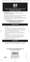
INSTALLATION TOOLS REQUIRED
• AC/DC Clamp meter
• Screwdriver set
• Socket Set
• Crimping Tool
• 4mm Black and Red Solar Flex Cable
INSTALLATION STEPS SUMMARY
Step 1 Read this manual thoroughly. In case of any ambiguities, contact our office for further advice
Step 2 Always ensure familiarity with all local safety procedures
Step 3 Mount the PV Panels
Step 4 Install element
Step 5 Install Geyserwise Dual Controller
Step 6 Install MPPT
Step 7 Recheck all connections
Step 9 Switch on Fuses on MPPT
Geyserwise Dual
Controller
12V 4Ah Battery
MPPT
PV System Installers Guide __________________________ Installation
System components
PV Panels
(number and size
depends on the system
configuration)
PTC Element
1500W AC, 900W DC
or 2200W AC, 900WDC.
Screwboss or Flangemount
available.

www.geyserwise.co.za
7
SAFETY PRECAUTIONS
Observe all precautions as set out in SANS 10142 when working with electricity.
Electricity on the geyser
An installer should always take precautions when working with electricity. The most important precautions
to perform before doing maintenance on a geyser are:
Test with a MULTIMETER to ensure that
there is no current on the wires. IMPORTANT
Make sure that there is no reading on the
multimeter.
Switch o the circuit breaker of the geyser
at the main DB. This is done to ensure that
there is no power supply to the geyser
Switch o the isolator switch in the roof.
The isolator switch acts as a switch to isolate
both the live an neutral from the main supply
should someone accidentally switch on the
main supply or the circuit breaker fails
PV System Installers Guide _____________________ Safety precautions

www.geyserwise.co.za
8
Electricity on PV Panels
PV modules can produce current and voltage when exposed to light of any intensity. Electrical current
increases with higher light intensity. DC voltage of 30 Volts or higher is potentially lethal. Contacting
the live circuitry of a PV system operating under light can result in lethal electric shock. De-energize PV
modules by removing them entirely from light or by covering their front surface with an opaque material.
Regard the safety regulations for live electrical equipment when working with modules that are exposed
to any light. Use insulated tools and do not wear metallic jewellery while working with PV modules.
In order to avoid arcing and electrical shock, do not disconnect electrical connections under load. Faulty
connections can also result in arcing and electrical shock. Keep connectors dry and clean, and ensure that
they are in proper working condition. Never insert metallic objects into the connectors, or modify them in
any way in order to secure an electrical connection.
Do not touch or handle PV modules with broken glass, separated frames or a damaged backsheet unless
the PV modules are first disconnected and you are wearing proper Protective clothing. Avoid handling PV
modules when they are wet. Never touch electrical connections that are wet without protecting yourself
with insulated gloves.
Make sure the fuses on the MPPT are in the off position when making any connections
Mounting of PV Panels
Rooftop PV systems should only be installed on dwellings that have been formally analysed for structural
integrity, and confirmed to be capable of handling the additional weighted load of PV system components,
including PV modules, by a certified building specialist or engineer.
For your safety, do not attempt to work on a rooftop until safety precautions have been identified and
taken, including without limitation fall protection measures, ladders or stairways, and personal protective
equipment.
For your safety, do not install or handle PV modules under adverse conditions, including without limitation
strong or gusty winds, and wet or frosted roof surfaces.
PV System Installers Guide _____________________ Safety precautions

www.geyserwise.co.za
9
INSTALLATION OF THE PV PANELS
Each manufacturer of PV panels will make available instructions as to how best to install its PV panels.
Be sure to read and follow instructions on the specific brand of PV panels used in the system. The below
information is based on information as contained in the guidance notes of Renesola PV panels.
General
Do not dismantle the Modules or tear up any labels.
Installation should be done by qualified professionals only.
Ensure that the correct connector pairs are used.
Do not touch the exposed cables or connectors.
De-energize PV modules by removing them entirely from light or by covering their front surface with an
opaque material.
System designers shall design an appropriate bracket and follow the instructions to fix the PV module
to the bracket.
Installation and maintenance shall be performed in accordance to all electrical safety regulations
Do not stand on the modules
Do not paint the modules or spray any material on the modules
Always transport the modules carefully and according to the manufacturer’s instructions. Take care that
the modules are not scratched as scratches may influence the efficiency of the modules
Installation
STEP1
Choose the location of the PV panels - be sure to choose a location where the panels will be fully exposed
to the sun and that the areas are not shaded. Look out for shade produced by trees or other buildings. In
the Southern Hemisphere the panels should face north at an angle calculated according to your location
Optimal angle for xed solar panels depending on installation position
45˚
37˚ – 45˚
26˚ – 37˚
13˚ – 26˚
0˚ – 13˚
13˚ – 26˚
26˚ – 37˚
37˚ – 45˚
PV System Installers Guide ______________ Installation of the PV panels

www.geyserwise.co.za
10
for a latitude up to 25° take your latitude and multiply it by 0,87
for a latitude between 25° to 50° take your latitude multiply by 0,87 after that you will add 3,1 degrees
for a latitude over 50° the most ideal angle will end up being approximately 45° degrees
As you can see you will need to know your current latitude to be able to count out the most ideal angle to
position your solar panels in. The easiest way to do this is to do a search for your location on Google maps
and then right click on the location and choose “what is here”. A green arrow will then appear, if you click
on that arrow you will get the GPS coordinates for that spot on the map. The first numbers is the latitude
of the spot. Use that number in your calculations. For example GPS coordinates for Goodwood, Cape Town
is given below.
STEP 2
Use a bracket structure that can withstand high winds. The bracket structure must be made of durable,
corrosion resistant and UV resistant materials
STEP 3
Choose a fixing method:
100 Townsend St
Cape Town 7460
-33.906552, 18.540870
Installed by nut and bolt:
Fix the module to the structure using the
pre-fabricated holes
Installed by xture
PV System Installers Guide ______________ Installation of the PV panels

www.geyserwise.co.za
11
PV system connection diagramme – Two panels seriers MPPT
STEP 4
Grounding
Negative system grounding is recommended
The ground wire shall be bare copper wire with no
insulation sleeve. Wire cable with cross sectional
area of 4mm2 to 6mm2 is recommended and
ground clamp is recommended (See picture)
STEP 5
Wiring and connection
Use 4mm or 6mm cable depending on distance of panels from the MPPT. 4mm for up to 20m.
For longer distances use 6mm Cable
Ensure that the correct connecters are used (At least 40 A)
PV System Installers Guide ______________ Installation of the PV panels
250W PV
panel
MPPT +
(Plug in using
supplied cables)
MPPT -
(Plug in using
supplied cables)
250W PV
panel
– ++ –

www.geyserwise.co.za
12
INSTALLATION OF THE ELEMENT
The element is a universal screwboss element suitable for geysers that are fitted with a screw-in element.
Please note that a separate flange must be purchased to accommodate for the thermostat. Each brand of
geyser has its own unique flange.
Screw in elements
Tools needed:
Phillips screwdriver
Screw-in element wrench
Your new element
Garden hose
Multi meter or circuit tester (to make sure power is off )
Installation steps
Be sure to use the same wattage, voltage, and flange style as your previous element.
1
Shut OFF electric power to water heater. See safety steps on page 6
2
Shut OFF cold water supply to the geyser, open the hot water faucet, attach a hose to the drain valve, open
the drain valve on the GEYSER and drain the water.
3
Remove access cover and fold back insulation.
4
Remove plastic terminal protector.
5
Check wires with a Multi Meter before attempting to
remove the wires.
6
Disconnect electric wires from element
7
Remove element using screw-in element wrench
8
Clean gasket area and threads
9
Install gasket on element
10
Close drain valve and turn ON cold water supply.
11
Allow all trapped air to escape from open hot water faucet until water has a constant flow, then close hot
water faucet. If leakage occurs, shut OFF cold water supply and tighten element or reposition gasket.
PV System Installers Guide ______________ Installation of the element

www.geyserwise.co.za
13
Flange Type Elements
Tools needed:
Phillips screwdriver
Socket wrench
Your new element
Garden hose
Volt meter or circuit tester (to make sure power if off )
Be sure to use the same wattage, voltage, and flange style as your previous element.
1
Shut OFF electric power to water heater. See safety steps on page 6
2
Shut OFF cold water supply to the geyser, open the hot water faucet, attach a hose to the drain valve,
open the drain valve on the GEYSER and drain the water.
3
Remove access cover and fold back insulation.
4
Check wires with a Multi Meter before attempting to
remove the wires.
12
Inspect wiring. If corrosion is present on wiring, cut and strip wire 1/2” (only if wire is long enough). If corrosion
is still present, or wire is not long enough consult electrician for wire replacement and wire gauge selection.
Loose, corroded or faulty wiring connections can cause heat build-up or fire at wiring terminals.
13
Connect electric wires to element. Tighten screws.
14
Replace plastic terminal protector.
15
Replace insulation and access cover. Tank must be properly filled with water and free of air before applying
electric power to prevent element damage.
p
16
Turn ON electric power to water heater.
White DC
Blue DC
Black AC
Red AC
PTC Element
PV System Installers Guide ______________ Installation of the element

www.geyserwise.co.za
14
5
Disconnect electric wires from element
6
Remove element mounting bolts using socket wrench. Note position of thermostat bracket to be rein-
stalled later.
7
Clean gasket area in tank
8
Install gasket into recess in tank.
9
Install element and thermostat bracket. Tighten bolts in diagonal pattern.
10
Close drain valve and turn ON cold water supply.
11
Allow all trapped air to escape from open hot water faucet until water has a constant flow. Close hot water
faucet.
12
Inspect wiring. If corrosion is present on wiring, cut and strip wire 1/2” (Only if wire is long enough). If
corrosion is still present, or wire is not long enough consult electrician for wire replacement and wire
gauge selection. Loose, corroded or faulty wiring connections can cause heat buildup or fire at wiring
terminals.
13
Connect electric wires to element. Tighten screws
14
Replace plastic terminal protector
15
Replace insulation and access cover
16
Tank must be properly filled with water and free of air before applying electric power to prevent element
damage.
17
Turn ON electric power to water heater
Simply Plug in the Anderson plug on tted on the White and Blue cables into the MPPT
White DC
Blue DC
Black AC
Red AC
PTC Element
PV System Installers Guide ______________ Installation of the element

www.geyserwise.co.za
15
PV System Installers Guide ______________ Installation of the element
www.geyserwise.co.za
Installation procedure steps
A summary of the installation steps are as follows:
1. Apply all safety measures.
2. Install the control box.
3. Install the display unit.
4. Remove existing thermostat and replace with new supplied thermostat.
5. Install LDR sensor.
6. Complete all electrical connections.
7. Set up the controller and all settings.
Switch o circuit breaker of geyser
at main DB. This is done to ensure that there
is no power supply to the geyser.
Switch o isolator switch in the roof.
The isolator switch acts as a switch to
isolate both live and neutral from the
main supply should someone
accidentally switch on the main supply
or the circuit breaker fails.
Test with a MULTIMETER to ensure
that there is no current on the wires.
IMPORTANT! Make sure that there is
no reading on the multimeter.
1 2
3
STEP 1: Apply all safety measures
An installer should always take precautions when working with electricity.
The most important safety precautions to perform BEFORE doing any maintenance on a geyser are:
STEP 2: Install control box
Find a dry place near the isolator switch. The control box must not be exposed to the elements!
6
GeyerWise Dual Controller
Instruction manual

www.geyserwise.co.za
16
PV System Installers Guide ______________ Installation of the element
www.geyserwise.co.za
STEP 3: Install the display unit
The display unit must be installed in a location
that is accessible to the end user, but not in reach
of children that might want to play with it.
The display unit provides valuable information on
the functionality and status of your hot water
system.
Draw the display unit cable from the unit to the
control box. Plug it into the three pin plug as
provided on the control box. It can only fit into
one plug.
The standard display cable of 5m is supplied.
Extension cables are available on request from
our offices. A maximum extension of 20m is
recommended.
Only use GeyserWise extention cables for
extensions!!!
Remove the existing thermostat by
disconnecting all the wires on the
connector terminal block of the
thermostat.
Replace the conventional element with
the GeyserWise AC/DC element as per
the AC/DC element instruction manual
and the wiring diagram on page 5.
1 2
STEP 4: Remove thermostat and replace with supplied geyser temperature probe
The geyser's thermostat needs to be removed. The geyser temperature probe provided by GeyserWise has
a built in probe that measures the temperature in the geyser. It also supplies information to the element
whether it should switch on or not.
The GeyserWise geyser temperature probe incorporates a thermal cut out to prevent electrical
overheating. The live feed to the element will be broken at temperatures above 90°C. When the cut out
switches off, it needs to be reset manually by pressing the red button on the thermal cut out.
7
GeyerWise Dual Controller
Instruction manual

www.geyserwise.co.za
17
PV System Installers Guide ______________ Installation of the element
www.geyserwise.co.za
Ensure that you insert the
geyser temperature probe into the
correct pocket.
Insert the new geyser temperature
probe and connect the live wires once
again on the connector terminal block.
The blue and white wires on the AC/DC
element is the DC connection. The white
wire is connected to the negative of the PV
panel in case a solid state relay is used or
the negative of the MPPT in case a MPPT
controller is used. The blue wire is
connected to the negative of the load side
of the solid state relay in case a MPPT
controller is used or the negative of the
MPPT controller in case the MPPT controller
is used. Please see diagrammes on page 5.
3 4
5
Push the plug connected to the
geyser temperature probe through
the hole as provided on the geyser.
Plug it into the dedicated plug as
provided on the control unit.
6
Black and red = 230V AC
Blue and white = DC
Black and red = 230V AC
Blue and white = DC
8
GeyerWise Dual Controller
Instruction manual
Plug the DC part of the element
into the MPPT Connector Cable
as supplied
5 6

www.geyserwise.co.za
18
PV System Installers Guide ______________ Installation of the element
www.geyserwise.co.za
1 2
The function of the LDR sensor is to
detect the quality of light outside.
STEP 5: Install the LDR sensor
You will be supplied with an extension cable.
Do not use any other extension than the
extension cable provided.
Plug the LDR sensor into the control box at
the dedicated port.
Connections on control box summary
LDR sensor
LDR sensor
LDR Sensor
LDR Sensor
Install outside.Do not install inside.
9
GeyerWise Dual Controller
Instruction manual
/