Page is loading ...

USER MANUAL
English
Pro20
Pro20i
User Manual
DOCUMENT #605597

Item #605597
Rev C, September 2016
For the latest version of this manual,
visit ysi.com
©2016 YSI Incorporated.
The YSI logo is a registered trademarks of YSI Incorporated.

CONTENTS
Warranty ................................................................................................i
Introduction
.........................................................................................1
Getting Started ....................................................................................1
Initial Inspection
.....................................................................1
Battery Installation
.................................................................1
Key Pad .................................................................................... 2
Connecting the Sensor and Cable
......................................3
Membrane Installation ........................................................... 5
Run Screen
..............................................................................6
Backlight
.................................................................................7
Powering Off
........................................................................... 7
Navigation ..............................................................................7
First Power On
........................................................................8
System Setup Menu ............................................................................9
DO Local% ..............................................................................9
Last Digit Suppression (LDS)
..............................................10
One Touch Calibration (One Touch Cal)
............................11
Audio ...................................................................................11
Contrast
.................................................................................11
Sensor Type ..........................................................................12
Membrane Type
...................................................................12
Auto Stable ...........................................................................13
DO Units................................................................................14
Temperature Units
................................................................14
Pressure Units
.......................................................................15
Language
..............................................................................15
Auto Shutoff ..........................................................................15
Resetting the System Setup Menu to Factory Default
......15
Exiting The System Setup Menu
.........................................16

Calibration .........................................................................................17
Temperature .........................................................................17
Barometer .............................................................................17
Dissolved Oxygen ................................................................17
Salinity Compensation Calibration .....................................21
Taking Measurements .......................................................................22
Saving and Viewing Data ..................................................................23
Saving Data ...........................................................................23
Viewing and Erasing Saved Data – Data Mode .................23
Principles of Operation ....................................................................25
Care, Maintenance and Storage ......................................................26
General Maintenance ..........................................................26
Sensor Maintenance ............................................................28
Sensor Storage .....................................................................32
Troubleshooting ................................................................................33
Specifications .....................................................................................35
Accessories / Part Numbers .............................................................35
Declaration of Conformity ................................................................37
Recycling ............................................................................................38
Battery Disposal ...................................................................38
Contact Information ..........................................................................39
Ordering and Technical Support ........................................39
Service Information ..............................................................39

i
WARRANTY
The YSI Pro20/Pro20i instrument is warranted for three (3) years from date
of purchase by the end user against defects in materials and workmanship,
exclusive of batteries and any damage caused by defective batteries.
Pro20/Pro20i cables are warranted for two (2) years from date of purchase
by the end user against defects in material and workmanship.
Pro20/Pro20i Polarographic sensors are warranted for one (1) year and
Galvanic sensors are warranted for six (6) months from date of purchase by
the end user against defects in material and workmanship.
Pro20/Pro20i instruments, cables & probes are warranted for 90 days
from date of purchase by the end user against defects in material and
workmanship when purchased by rental agencies for rental purposes.
Within the warranty period, YSI will repair or replace, at its sole discretion,
free of charge, any product that YSI determines to be covered by this
warranty.
To exercise this warranty, call your local YSI representative, or contact
YSI Customer Service in Yellow Springs, Ohio at +1 937 767-7241, 800-
897-4151 or visit www.ysi.com (Support tab). Send the product and proof
of purchase, transportation prepaid, to the Authorized Service Center
selected by YSI. Repair or replacement will be made and the product
returned, transportation prepaid. Repaired or replaced products are
warranted for the balance of the original warranty period, or at least 90
days from date of repair or replacement.
LIMITATION OF WARRANTY
This Warranty does not apply to any YSI product damage or failure caused
by:
1. Failure to install, operate or use the product in accordance with YSI’s
written instructions;
2. Abuse or misuse of the product;
3. Failure to maintain the product in accordance with YSI’s written
instructions or standard industry procedure;
4. Any improper repairs to the product;
5. Use by you of defective or improper components or parts in servicing
or repairing the product;
6. Modification of the product in any way not expressly authorized by YSI.
THIS WARRANTY IS IN LIEU OF ALL OTHER WARRANTIES, EXPRESSED OR
IMPLIED, INCLUDING ANY WARRANTY OF MERCHANTABILITY OR FITNESS
FOR A PARTICULAR PURPOSE. YSI’S LIABILITY UNDER THIS WARRANTY
IS LIMITED TO REPAIR OR REPLACEMENT OF THE PRODUCT, AND THIS
SHALL BE YOUR SOLE AND EXCLUSIVE REMEDY FOR ANY DEFECTIVE

ii
PRODUCT COVERED BY THIS WARRANTY. IN NO EVENT SHALL YSI BE
LIABLE FOR ANY SPECIAL, INDIRECT, INCIDENTAL OR CONSEQUENTIAL
DAMAGES RESULTING FROM ANY DEFECTIVE PRODUCT COVERED BY
THIS WARRANTY.

1
INTRODUCTION
Thank you for purchasing the YSI Pro20/Pro20i, an instrument from the
YSI Professional Series product family. The Pro20 features user-replaceable
cables, while the Pro20i features an integral (i.e. built-in) cable. Sensors
are user-replaceable on Pro20 and Pro20i cables.
The Pro20/Pro20i features an impact resistant and waterproof (IP-
67) case, backlit display, user-selectable sensor options, internal
barometer, and a rugged, rubber over-mold case.
The Pro20/Pro20i provides valuable instructions and prompts near
the bottom of the display that will guide you through operation and
use. However, reading the entire manual is recommended for a better
understanding of the Pro20/Pro20i’s features.
GETTING STARTED
INITIAL INSPECTION
Carefully unpack the instrument and accessories and inspect for
damage. Compare received parts with items on the packing list. If
any parts or materials are damaged or missing, contact YSI Customer
Service at 800-897-4151 (+1 937 767-7241) or the authorized YSI
distributor from whom the instrument was purchased.
BATTERY INSTALLATION
The instrument requires 2 alkaline C-cell batteries. Under normal
conditions, the average battery life is 400 hours at room temperature
without using the back light. A battery symbol will blink in
the lower, left corner of the display to indicate low batteries when
approximately 1 hour of battery life remains.
To install or replace the batteries:
1. Turn the instrument off and flip over to view the battery cover
on the back.
2. Unscrew the four captive battery cover screws.
The Pro20/Pro20i can not communicate to a PC via a Pro Plus
communications saddle. Connecting the Pro20/Pro20i to a
communication saddle may cause erratic instrument behavior.
i

2
3. Remove the battery cover and remove the old batteries if
necessary.
4. Install the new batteries, ensuring correct polarity alignment
(figure 1).
5. Place the battery cover on the back of the instrument and
tighten the four screws. Do not over-tighten.
Figure 1. Pro20/Pro20i with battery cover removed.
Notice battery symbols indicating polarities.
The waterproof instrument case is sealed at the factory and
is not to be opened, except by factory-authorized service
technicians. Do not attempt to separate the two halves of the
instrument case as this may damage the instrument, break the
waterproof seal, and will void the warranty.
i
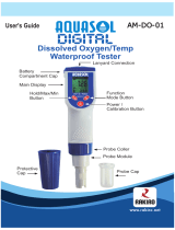
KEY PAD
Figure 2, Keypad
1
2
3
4
5
6

3
Number Key Description
1
Calibrate
Press and hold for 3 seconds to calibrate.
Initiates One Touch Calibration. Opens
Calibrate menu from the run screen if
One Touch Calibration is disabled.
2
Up Arrow
Use to navigate through menus, to
navigate through box options along
the bottom of the Run screen, and
to increase numerical inputs.
3
Power and Backlight
Press once to turn instrument on. Press a
second time to turn backlight on. Press a
third time to turn backlight off. Press and
hold for 3 seconds to turn instrument off.
4
Menu
Use to enter the System Setup
menu from the run screen.
5
Enter
Press to confirm entries and selections.
6
Down Arrow
Use to navigate through menus, to
navigate through box options at
the bottom of the Run screen and
to decrease numerical inputs.
CONNECTING THE SENSOR AND CABLE
CONNECTING THE SENSOR
“Sensor” refers to the removable portion or electrode sensing portion
of the cable assembly, i.e. the dissolved oxygen sensor. “Bulkhead”
refers to the portion of the cable with the single-pin connector (Figure
3).

4
The Pro20/Pro20i has two compatible sensors for use with a field cable:
Polarographic – This sensor has a black sensor body and is engraved
with the model number 2003. Polarographic will be abbreviated Polaro
in the instrument’s menu.
Galvanic – This sensor has a grey sensor body and is engraved with the
model number 2002.
For information about the differences on the two sensor types, see
Sensor Type in the System Setup menu section and/or the Principles of
Operation section of this manual.
If using a ProBOD sensor/cable assembly, there is no need to install a
sensor because it has a built in Polarographic dissolved oxygen sensor.
Before installing either sensor or connecting the cable (Pro20
only) to the instrument, the Sensor Type must be configured
for the sensor being installed/connected. Failure to do this
may result in damage not covered under warranty. The
instrument will step you through this setup the first time it
is powered on. See the System Setup menu section of this
manual for instructions on configuring the Sensor Type after
the first power on.
i
1. Ensure both the sensor connector and sensor port on the cable are
clean and dry.
2. Grasp the sensor with one hand and the cable bulkhead in the
other.
3. Push the sensor into the connector on the cable until it is firmly
seated and only 1 o-ring is visible. Failure to properly seat the
sensor may result in damage.
4. Twist the sensor clockwise to engage threads and finger tighten.
Do NOT use a tool. This connection is water-tight.
For more detailed instructions, please refer to the sensor installation
sheet that is included with each sensor.
Figure 3

5
Connecting the Cable (Pro20 Only)
The Pro20 is designed for field and laboratory use. It is compatible with
two different cable options:
1. The field rugged cable is available in standard lengths of 1, 4, 10,
20, 30, and 100 meters with special lengths available between 30
and 100 meters. This cable has a built in temperature sensor and
includes a port for the dissolved oxygen sensor.
2. The ProBOD is a 1 meter probe/cable assembly with built in
Polarographic dissolved oxygen and temperature sensors. It has
an AC powered motor for sample stirring and is designed to fit into
a 300 ml BOD bottle.
To connect the cable, align the keys on the cable connector to the slots
on the instrument connector. Push together firmly and then twist the
outer ring until it locks into place (figure 4). This connection is water-
proof.
Figure 4, Note the keyed connector.
When disconnected, the sensor and cable’s sensor connectors
are NOT water-proof. Do not submerge the cable without a
sensor installed. When disconnected, the cable’s instrument
connector and the connector on the instrument maintain a
waterproof, IP-67 rating.
i
MEMBRANE INSTALLATION
The dissolved oxygen sensor is shipped with a dry, protective red cap
that will need to be removed before using. It is very important to put a
new membrane with electrolyte solution on the sensor after removing
the red cap.

6
Prepare the membrane solution according to the instructions on the
bottle. After mixing, allow the solution to sit for 1 hour. This will help
prevent air bubbles from later developing under the membrane.
Ensure you are using the correct electrolyte solution for the correct
sensor. Galvanic sensors utilize electrolyte with a light blue label
and Polarographic sensors utilize electrolyte with a white label. The
Dissolved Oxygen sensor is supplied with cap membranes specific
to the sensor type ordered (Polarographic or Galvanic). 5913 and
5914 membrane kits are for Galvanic sensors and the 5908 and 5909
membrane kits are for Polarographic sensors.
Remove and discard or save the red protective cap. Thoroughly rinse
the sensor tip with distilled or deionized water. Fill the cap membrane
3⁄4 full of electrolyte solution, then tap the cap with a finger to release
any trapped air. Be careful not to touch the membrane portion of the
cap. Thread the membrane cap onto the sensor, moderately tight.
Do not use a tool. It’s typical for some of the electrolyte solution to
spill over. It is best to allow the new cap to remain on a new sensor
overnight before trying to calibrate. For detailed instructions on
changing a membrane cap, see the Care, Maintenance, and Storage
section of this manual.
RUN SCREEN
Press the power/backlight key to turn the instrument on. The
instrument will run through a self test and briefly display a splash screen
with system information before displaying the main Run screen (figure
5). The first time the Pro20/Pro20i is turned on, it will step through
language, sensor, and membrane selections; see the First Power On
section of this manual for more information.
Figure 5, Run screen.

7
BACKLIGHT
Once the instrument is powered on, pressing the power/backlight key
will turn on the display backlight. The backlight will remain on until
the key is pressed again or after two minutes of not pressing any key
on the keypad.
POWERING OFF
To turn the instrument off, press and hold the power/backlight key
for three seconds.
NAVIGATION
The up and down arrow keys allow you to navigate through the
functions of the Pro20/Pro20i.
Navigating the Run Screen
When in the Run screen, the up and down arrow keys will move the
highlighted box along the bottom options. Once a box is highlighted,
press enter
to access the highlighted option.
Description of Run screen box functions from left to right:
Option Description
Barometer Highlight and press enter to calibrate the
instrument’s internal barometer.
Salinity
compensation
value
Highlight and press enter to adjust the salinity
compensation value that is used for the
dissolved oxygen mg/L measurement.
SAVE
Highlight and press enter to save displayed
data to memory.
DATA
Highlight and press enter to view and/or erase
saved data.

8
Navigating the System Setup Menu
When in the System Setup menu, the up and down arrow keys will
move the highlighted bar up and down the system setup options. See
the System Setup menu section of this manual for more information
about these options.
FIRST POWER ON
The instrument will step through an initial configuration when powered
on for the first time. This will set the language, sensor, and membrane
options. Use the up or down arrow keys to highlight the appropriate
language, sensor, and membrane, then press enter to confirm (Figures
6, 7, and 8). The Sensor Type must be configured for the sensor
installed. Failure to do this may result in damage not covered under
warranty. If an incorrect option is selected, it may be changed in the
System Setup menu.
Figure 6, Language selection
Select Sensor Type:
Polaro (black)
Galvanic (grey)
Use to select
sensor type
Press to confirm
Select Membrane
Type:
1.25 (Yellow)
2.0 (Blue)
Use to select
membrane
Press to confirm
Figure 7, Sensor selection Figure 8, Membrane selection

9
After selecting a language, sensor, and membrane, the run screen will
appear. The next time the instrument is powered up the run screen
will appear immediately after the self check. If the sensor type or
membrane type is changed, ensure that it updated in the System Setup
menu.
SYSTEM SETUP MENU
Press the menu key to access the System Setup menu. The System
Setup menu contains three screens notated as ‘pages’. The current
page is indicated near the bottom of the display (figure 9).
DO LOCAL%
DO Local% can be enabled or disabled by using the up or down arrow
keys to highlight it and then pressing enter
. An ‘X’ in the box next to
DO Local% indicates it is enabled (Figure 9).
Figure 9, DO Local% is enabled.
When DO Local% is enabled, DO% values will be expressed as %L on
the Run screen.
DO Local% allows for localized % saturation measurements, but does
not affect the mg/L readings. When enabled, the DO%L calibration
value is always 100% regardless of the altitude or barometric
pressure of the location. This deviates from YSI’s traditional method of
expressing DO% saturation where the % calibration value decreases
with a decrease in barometric pressure, i.e. an increase in altitude (See
appendix A). To determine the % calibration value when DO Local% is
disabled, divide the local, true barometric pressure in mmHg by 760
and then multiply by 100.

10
Example: 750/760 = 0.9868 x 100 = 98.68% calibration value when
DO Local is disabled.
When DO Local% is enabled, the Pro20/Pro20i corrects for barometric
pressure for each DO measurement instead of during calibration.
Example:
Instrument #1 with DO Local% enabled:
At 737 mmHg barometric pressure, roughly 841 ft above sea level, the
instrument would calibrate to 100%.
When taking measurements at the same location (737 mmHg) in a 20°C
fresh water sample that is completely air-saturated, the instrument
would read:
DO %L value = 100%
DO mg/L value = 8.81 mg/L (9.09
1
x .9697
2
)
Instrument #2 DO Local% disabled:
At 737 mmHg barometric pressure, roughly 841 ft above sea level, the
instrument would calibrate to 737/760 x 100% = 96.97%
When taking measurements at the same location (737 mmHg) in a 20°C
fresh water sample that is completely air-saturated, the instrument
would read:
DO% value = 96.97%
DO mg/L value = 8.81 mg/L (9.09
1
x .9697
2
)
Hence, the mg/L readings are unaffected by DO Local%.
1.) Value from oxygen solubility table (Appendix B).
2.) 737/760 x 100%, correction for barometric pressure.
LAST DIGIT SUPPRESSION (LDS)
Last Digit Suppression (LDS) can be enabled or disabled by using the
up or down arrow keys to highlight it and pressing enter
. An ‘X’ in
the box next to LDS indicates it is enabled.
LDS rounds the DO value to the nearest tenth; i.e. 8.25 mg/L becomes
8.3 mg/L. LDS is automatically disabled during calibrations.

11
ONE TOUCH CALIBRATION (ONE TOUCH CAL)
One Touch Calibration can be enabled or disabled by using the up or
down arrow keys to highlight One Touch Cal and pressing enter
.
An ‘X’ in the box next to One Touch indicates it is enabled.
When One Touch Cal is enabled, press and hold the calibration
key
for 3 seconds while in the run screen to calibrate Dissolved Oxygen
to the barometer reading and salinity correction value. For more
information on One Touch Calibration, see the Calibration section of
this manual.
AUDIO
Audio can be enabled or disabled by using the up or down arrow keys
to highlight Audio and pressing enter. When enabled, there will be an
‘X’ in the box next to Audio.
When Audio is enabled, the Pro20/Pro20i will beep twice to indicate
stability when Auto Stable is enabled. The instrument will also beep
when a key is pressed. When Audio is disabled, the Pro20/Pro20i will
not beep.
CONTRAST
To adjust the display Contrast, use the up or down arrow keys to
highlight Contrast, then press enter. Next, use the up or down arrow
keys to adjust the contrast. The up arrow key will darken the contrast
and the down arrow key will lighten the contrast. After adjusting the
contrast, press enter to save and exit the Contrast adjustment function.
Alternate Contrast Adjustment Option
If necessary, there is an alternate method of adjusting the contrast. To
adjust the contrast, press and hold the menu key, then press the up
arrow key to darken the contrast or press the down arrow key to lighten
the contrast.

12
SENSOR TYPE
The instrument’s Sensor Type must be configured for the
sensor installed. Failure to do this may result in damage not
covered under warranty. If you observe readings very close
to 0 or extremely high readings, e.g. 600%, your Sensor Type
setting may be set incorrectly.
i
Sensor Type sets the type of dissolved oxygen sensor being used;
either polarographic (black) or galvanic (grey).
Use the up or down arrow keys to highlight Sensor Type, then press
enter
to open a submenu. Highlight the sensor type corresponding
to the sensor installed on the cable and press enter to confirm. The
enabled sensor type will have an ‘X’ in the box next to it. Next, use the
down arrow key to highlight the ESC – Exit box, then press enter to
save changes and to close the sensor submenu.
If using a ProBOD sensor/cable assembly, the sensor type should be
set to polarographic.
The Pro20/Pro20i has two compatible sensors for use with a field cable:
• Polarographic – This sensor has a black sensor body and is
engraved with the model number 2003. Polarographic will be
abbreviated Polaro in the instrument menu.
• Galvanic – This sensor has a grey sensor body and is engraved
with the model number 2002.
In terms of physical configuration, membrane material and general
performance, YSI Pro Series galvanic sensors are exactly like the Pro
Series polarographic sensors. The advantage of using galvanic sensors
is convenience. Galvanic sensors provide an instant-on sensor without
the need for warm-up time but this affects the life of the sensor.
Polarographic sensors last longer and have a longer warranty but
require a 5-15 minute warm-up time before use or calibration.
MEMBRANE TYPE
Membrane Type sets the type of membrane used on the dissolved
oxygen sensor; either 1.25 PE (Yellow) or 2.0 PE (blue). Use the up
or down arrow keys to highlight Membrane Type and press enter to
open the submenu. Highlight the membrane type corresponding to
the membrane installed on the sensor and press enter to confirm. The

13
enabled membrane type will have an ‘X’ in the box next to it. Use the
down arrow key to highlight the ESC – Exit box and press enter to save
changes and to close the membrane submenu.
The dissolved oxygen sensor is supplied with membranes specific
to the sensor type and are color coded as described in the following
tables.
Galvanic Membrane Kits:
Model Color Material Description
5913 Yellow 1.25 mil
polyethylene (PE)
Faster response time and less flow
dependence than traditional FEP
membranes.
5914 Blue 2.0 mil
polyethylene (PE)
Less flow dependence than 1.25 mil
membrane but little slower response.
Polarographic Membrane Kits:
Item Color Material Description
5908 Yellow 1.25 mil
polyethylene (PE)
Faster response time and less flow
dependence than traditional FEP
membranes.
5909 Blue 2.0 mil
polyethylene (PE)
Less flow dependence than 1.25 mil
membrane but a little slower response.
Selecting a Dissolved Oxygen Membrane:
Membrane
Type
Flow Dependence
After 4 Minutes
Required Sample
Movement
Typical Response
Time (T-95)
5913, 5908
Yellow
25% 6 inches/second 8 seconds
5914,
5909 Blue
18% 3 inches/second 17 seconds
AUTO STABLE
Auto Stable utilizes preset values to indicate when a reading is stable.
The preset values are adjustable in the System Setup menu. The user
can input a % change in dissolved oxygen readings (0.0 to 1.9) over ‘x’
amount of time in seconds (3-19).
Highlight Auto Stable and press enter
to expand the submenu.
Use the up or down arrow keys to highlight the DO% Change or
seconds (secs) input field, then press enter to make the highlighted
field adjustable. Use the up and down arrow keys to adjust the selected
value, then press enter to confirm changes. Once you have confirmed

14
any changes, highlight the ESC-Exit box and press enter to close the
Auto Stable submenu.
To disable Auto Stable, set the DO% Change input to 0.0.
When Auto Stable is enabled, an
AS
symbol will display next to the
dissolved oxygen value on the run screen and blink during stabilization.
When the dissolved oxygen value has stabilized based on the Auto
Stable settings, the
AS
will display steadily and the instrument will
beep twice if Audio is turned on.
DO UNITS
Highlight DO Units and press enter to open a submenu that allows
you to select the dissolved oxygen units to be displayed on the Run
screen. Highlight the desired unit(s) and press enter to enable or
disable. An enabled dissolved oxygen unit will have an ‘X’ in the box
next to it. Highlight the ESC-Exit box and press enter to save any
changes and to close the DO units submenu.
There are three options for displaying dissolved oxygen:
• mg/L will show DO readings in milligrams per liter on a scale
from 0 to 50 mg/L.
• ppm (parts per million) is equivalent to mg/L and will show the
DO reading on a scale from 0 to 50 ppm.
• % will show DO readings in a % saturation from 0 to 500%. This
value will be expressed as %L when DO Local% is enabled.
Both % or %L and mg/L or ppm can be displayed simultaneously on
the screen.
TEMPERATURE UNITS
Highlight Temperature Units and press enter to open a submenu
that allows you to change the temperature units displayed on the Run
screen. Highlight the desired unit (Celsius or Fahrenheit) and press
enter to enable. The enabled temperature unit will have an ‘X’ in the
box next to it. Only one unit may be enabled at a time. Highlight the
ESC-Exit box and press enter to save any changes and to close the
Temperature Units submenu.
/