Page is loading ...


2
TABLE OF CONTENTS
Subject Page
Introduction ..................................................................................................................................................... 3
Inspection ........................................................................................................................................................ 3
Installation ....................................................................................................................................................... 3
Operation ......................................................................................................................................................... 4
Typical Installations ........................................................................................................................................ 4
Calibration Curve/Table .................................................................................................................................. 5
Actual Standard and Mass Flow Equations ................................................................................................ 5-7
Reading your Laminar Flow Element Curve/Table ......................................................................................... 9
Correction Factor Tables/Curves
Air Humidity for Density ........................................................................................................................... 8
Air Humidity for Viscosity ......................................................................................................................... 8
Pressure .................................................................................................................................................... 12
Air Viscosity ............................................................................................................................................. 13
Air Temperature/Viscosity ....................................................................................................................... 14
Temperature .............................................................................................................................................. 15
Maintenance .................................................................................................................................................. 14
Troubleshooting ............................................................................................................................................. 15
LFE Dimensions ............................................................................................................................................ 17

3
Introduction
Because of their inherently high accuracy, stable calibration, excellent response time and repeatability,
Laminar Flow Elements (LFEs) excel in critical gas and air flow measurements and are frequently utilized
in validating calibration standards. Standard models are available to measure as little as 0.2 SCCM (5.9
E-06 SCFM) to as much as 2250 SCFM at standard conditions. Custom models for up to 15,000 SCFM of
air are available. Stainless steel or aluminum materials make LFEs compatible with most gases and flow
rate of gas mixtures can also be measured when the percentages of component gases and mixture properties
are known. Higher accuracies can be achieved when used in conjunction with the Meriam MDT500
multivariable transmitter and software package. The LFE matrix is made from individual SS tubes or
windings of SS foil, these tubes are long enough, relative to their inside diameter to cause laminar flow to
occur inside each tube, the result is a near linear relationship between DP and flow rate. The DP generated
across the matrix responds very quickly to changes in flow and pressure loss to the system is reduced as
each LFE is sized to produce no greater than 8” water column at maximum flowing conditions. Individual
tube diameters are very small so flowing gases need to be clean and dry to preserve the calibration.
Filtered inlet versions of most LFE models are available to keep the matrix clean and the calibration
constant.
This manual covers models 50MK10, 50MW20, 50MR2, 50MJ10, 50MC2 and 50MY15. For descriptions,
dimensions and capacities of these elements refer to Meriam Bulletin, File No. 501:215
Special
Precautions
When Handling Matrix
Elements
The Meriam LFE depends on the precise fabrication of a matrix metering element for its basic
accuracy.
These
elements are manufactured from .001 inch stainless steel stock and are carefully
fabricated. Exercise extreme care when
handling
the
exposed
element to make sure the end faces are
not gouged or damaged in any fashion. Gouges or damage to the
end
surfaces may produce nonlinear
resistance to flow
and
introduce
error.
If the end surface becomes damaged, the accuracy
of
the
element
may be
restored
by
recalibration
at
the
factory.
Inspection
1. Make sure you have
unpacked
all
instructions and
other data that accompanied the unit.
2. Visually inspect for any signs of damage. There
must
be no nicks or scratches, surfaces of the
LFE
should be
clear.
3. Units are shipped with a cap plug in each
opening which
protects the ends and
pressure
taps.
Remove these
cap
plugs.
4. Visually inspect matrix surface and inside
housing. No capillaries should be blocked unless
specified in special applications.
Installation
Make sure the line is free of dirt and other foreign materials. The metered gas must be clean. In-line
use of filters
is
recommended.
Connections
to the
differential
pressure
instrument
should be made
with equal lengths of 1/4" I.D
hose,
tubing or pipe. All instrument connections must be
leak-
free.
Install temperature sensor 2-diameters upstream of the element. Inlet absolute pressure instrument,
when needed
,
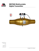
must be connected close to the LFE at the inlet pressure tap. Figure 1 shows several typical
LFE installations.
Install the LFE in the line using hose
connectors,
flanges, tubing or pipe, as desired. Position the LFE
in any orientation. Horizontal is the most common. Orient the high-pressure and low-pressure sensing
ports in
any
angular direction. Flow must be in the direction of
the
arrow on the
LFE. Avoid
disturbances upstream of the LFE. Good
measurement practices dictate an adequate straight
run
of the
pipe up and downstream of the element. In most
installations,
10
diameters
upstream and 5
diameters
downstream are
adequate.
Where
installation
makes straight pipe runs
impos
sible, LFE's can be calibrated with piping
configurations
that duplicate installation
.
This special calibration
assures installed accuracy. In these
applications, consult Meriam regarding calibration.

4
Operation
Establish
flow
through
the LFE.
Measure the differential
pressure between high pressure sensing
port and low pressure sensing port. Measure the inlet gas
temperature.
For standard or mass flow
rates, measure absolute line pressure. Refer to calibration curve/table instructions for flow rate
calculations.
Standard or Mass Flow Rate
Actual Volumetric Flow Rate

5
Calibration Curve Table
Meriam performs an air calibration of the LFE using a master flowmeter that is traceable to the National
Institute of Standards and Technology (NIST). The calibration data is standardized to an equivalent dry gas
flow rate at 70ºF (21.1ºC) and 29.92 inches Hg absolute (101.3 kPa abs.). (The customer may request
another standard condition such as OºC.) It is then possible to determine the actual or standard volumetric
flow rate at your flowing conditions. Each LFE has at least one calibration curve or table. The standard
curve/table is for dry air flow rate in units of cubic feet per minute (CFM) versus the differential pressure
(DP) in inches of water referenced to 4ºC produced by the LFE. You may request a curve/table for a
different gas and/or for different flow rate units. Each curve/ table is generated using a quadratic (second
order) equation.
B
x DP + C x
DP²
=
Flow
The calibration constants B and C are printed on
each
curve/table.
Actual Volumetric Flow
Rate
The LFE determines the actual volumetric flow rate. To obtain the actual volumetric flow rate, the
differential
pressure across the LFE and the inlet temperature to the LFE is measured. Using the
calibration curve/table
asso
ciated
with the
particular
LFE; a flow rate
value is
obtained by either
1) reading the value from the curve/table or:
2) using the formula,
B
x DP + C x
DP²
=
Flow
Each curve has unique constants B and C.
Multiply
this flow rate value by the ratio:
or / µf. The product is the actual volumetric
flow
rate. (The curve/table lists the type of gas used
to generate the
curve/table.)
Actual volumetric flow rate= (B x DP +C x
DP²) x (
)
or MDT 500
Laminar Flow Systems
Figure1: Typical Installations of Laminar Flow Elements Actual, Standard, or Mass Flow

6
To help calculate the viscosity of air at flowing temperature, a viscosity equation based on temperature is
included in this instruction manual (see Table A-32422). The equation is from “tables of Thermodynamic
and transport Properties of Air, Argon, Carbon Dioxide, Oxygen, and Steam.” All other gas viscosity
equations are obtained from "Physical and Thermodynamic Properties of Pure Chemicals" Table A-31986
lists the values of / µf for air from 50-159ºF at 1º intervals when the standard temperature is 70°F.
*Note: If you are flowing wet air, a humidity correction factor for viscosity must be used. The difference
between wet-air viscosity (µwet and dry-air viscosity (µdry) increases with temperature and humidity, at
80ºF and 80% relative humidity, the ratio of µwet / µdry is .997.
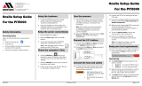
Figure 2 is a graph of the ratio µwet / µdry of air from 50 to 150ºF and from 10 to 90% relative humidity.
The viscosity of the flowing wet air becomes the value from the dry-air viscosity equation times the ratio
µwet / µdry
µf = µwet air =
x
Where T = ºK
The curve/table may have DP units
of
1) inches of water column (WC)
2) centimeters of WC
3) millimeters of WC
4)
pascals
5)
kilopascals
Whenever a pressure is expressed in
units of water,
the
water temperature reference
must be given.
The
calibration
curve uses 4°C for the water
temperature
reference. Some
devices
use a water
temperature reference of 20ºC and others may use other
temperature
references. If no temperature
reference is given on the DP instrument or in
its instruction manual, consult the manufacturer. If the
DP measuring device has a water
temperature reference
other than 4º, correct the
DP
reading by using
the following equation:
DP @ 4ºC = DP (device) x
Water
Temperature
Water Density (lbs/ft³)
4.0°C (39.2°F) 62.426
20.0°C (68.0°F) 62.316
15.5°C (60.0°F) 62.366
21.1°C (70.0°F) 62.301
The DP @ 4ºC value should be used with the curve/table.
Standard Volumetric Flow
Rate
The word "standard" when associated with flow
rate,
means the flow rate has been normalized to an
assigned
standard
pressure
and
temperature.
If standard
volu
metric flow rate is desired, the actual
volumetric flow rate is multiplied by the ratios.
and

7
Be sure to use the same absolute units for
pressure
(i.e. PSIA, mm Hg absolute,
...)
and temperature
(ºK or ºR). The result is the standard volumetric flow rate at
the
given standard conditions.
Standard volumetric flow rate
=
Actual volumetric flow rate x
x
This equation can be rewritten: (B x DP + C x DP²) x
x
x
Table A-31031 lists the values of Pf/
Pstd
absolute line pressures from 26”Hg at 0.05” Hg intervals.
The standard pressure is 29.92” Hg absolute for this table. Table A-32422 lists the values of
(Tstd / Tf) x (µstd / µf) for air from 50 to 159ºF in 1º intervals. The standard temperature is 70ºF
(529.67ºR) for this table.
Note: If you are flowing wet air, a humidity correction factor for standard volumetric flow rate must
be
used.
The difference between wet-air density
(Pwet)
and dry-air density (Pdry) increases with
temperature and humidity. At 80°F and 80% relative humidity, the ratio of
Pwet
/ Pdry is .990. Table
A-35600 lists the ratio
Pwet
/ Pdry of air from 40 to 100°F and from 20 to 100%
relative
humidity.
The equation for standard volumetric flow rate of flowing wet air becomes:
Standard Volumetric Flow
Rate
Wet Air
=
(B x DP + C x DP²) x
x
x
x
Mass Flow Rate
Multiply the standard volumetric flow rate by the density of the flowing gas at standard conditions to
obtain the mass flow rate of that gas.
Mass Flow rate = Standard volumetric flow rate x density @ standard conditions
Summary
Curve/table value @ DP = (B x DP + C x DP²)
Actual volumetric flow rate = (B x DP + C x DP²) x
Standard volumetric flow rate = Actual volumetric flow rate x
x
Mass flow rate = Standard volumetric flow rate x density @ standard conditions

8
Table A-35600 (NBSIR
83-2652)
Humidity Correction Factor for Air =
P
wet
/
Pdry
% Relative Humidity
°F
20%
40%
60%
80%
100%
40
.9993
.9987
.9981
.9975
.9969
50
.9990
.9981
.9973
.9964
.9955
60
.9986
.9973
.9960
.9948
.9934
70
.9981
.9962
.9944
.9925
.9907
80
.9974
.9948
.9922
.9895
.9870
90
.9964
.9928
.9892
.9855
.9818
100
.9951
.9902
.9854
.9805
.9756
0.96
0.97
0.98
0.99
1
50 60 70 80 90 100 110 120 130 140 150
Air Viscosity Correction Factor for Humidity, Uwet/Udry
Temperature oF
Figure2: Relative humidity correction factor for air viscosity. A-35500 Kestin &
Whitelaw
10% Humidity
20% Humidity
30% Humidity
40% Humidity
50% Humidity
60% Humidity
70% Humidity
80% Humidity
90% Humidity

9
Determining Flow from your Laminar Flow Element
Calibration
Curve/Table
The curve/table of each LFE is normalized to standard conditions listed by multiplying the calibration
data points by the ratio
of:
Therefore, you should NOT read the flow rate directly from the curve/table unless your flow
temperature
and
pressure are identical to the standard conditions.
The
following steps must be taken to
determine flow rate at flowing conditions other than standard.
1. Measure and correct to 4ºC and if
necessary,
the DP across the LFE.
2. Measure and record the inlet
temperature (always)
and absolute line pressure (for
standard or mass flow rates). Convert both values to absolute units.
3. Follow the AIR FLOW or GAS OTHER THAN
AIR
guidelines below
Model 50MK10 All Other Models
Air Flow
Select the proper flow
curve/table
for the LFE
being
used.
Standard Volumetric Flow Rate
1) To obtain standard volumetric flow rate if inlet
pres
sure and
temperature
are other than
29.92"
Hg
absolute and 70ºF, respectively, find the flow rate (Q) that corresponds to the corrected DP.
Multiply Q
by
temperature/viscosity and pressure corrections shown on charts A-32422 and
A-31031, respectively, to
bring
flow to standard conditions of 29.92" Hg and
70ºF.
2) At flowing
conditions
of
70
º
F
and 29.92" Hg,
read
curve directly in standard volumetric
flow rate.
Flow, Q
0 1 2 3 4 5 6 7 8
Differential Pressure,
Inch of Water @ 4ºC
Flow, Q
0 1 2 3 4
Differential Pressure,
Inch of Water @ 4ºC

10
Actual Volumetric Flow Rate
1) To obtain actual volumetric flow rate at inlet
flowing
temperature
other than
70ºF,
find
the flow rate
(Q)
that corresponds to the corrected DP. Multiply Q
by
the viscosity correction only.
See chart A-31986 for corrections.
2) At
flowing
inlet
temperature
of 70ºF read curve
directly in actual volumetric flow rate.
Actual volumetric flow rate equals standard
volumetric
flow rate when flowing conditions are 70ºF
and 29.92" Hg.
Notify Meriam if your flowing gas is not air
and/or
standard conditions are different from 70ºF and
29.92"
Hg
absolute. A special curve/table can be provided list
ing
the gas being flowed. The gas
viscosity
correction, µstd / µf
will
reference
the gas and/or new
standard temperature value
,
if
applicable. Table
A-32422 or
A-31986 cannot be used for gases other than air.
Gas Flow Other Than Air/Standard Conditions From 70°F and 29.92” Hg ABS.
Select the proper flow
curve/table
for the LFE
being
used.
Standard Volumetric Flow Rate
1) To obtain standard
volumetric
flow rate if the
inlet
temperature and pressure are different from
standard,
read the flow rate (Q) from the
curve/table corre
sponding to the corrected differential
pressure
(DP).
Calculate
the
viscosity
at the flowing
temperature
using the viscosity equation
for the flowing gas.
Then
calculate the viscosity correction factor (µcf)
using
µcf =
Locate the
pressure correction
factor (Pcf) for
the
flowing
inlet
pressure
on chart
A-31031 or
calculate the correction factor
using
Pcf =
Locate the temperature correction factor (Tcf) for
the
flowing temperature
on chart
A-35700
or
calculate
using
Tcf =
Multiply Q from the curve/table by the viscosity
cor
rection factor (µcf), the pressure correction factor
(Pcf)
and the temperature correction factor (Tcf).
This
product
will give the flow rate of a particular
gas at the
standard conditions.
2) At flowing inlet conditions equal to the standard conditions
,
read curve/table directly in standard
volumetric flow
rate.

11
Actual Volumetric Flow Rate
1) To obtain actual volumetric flow rate if the inlet
temperature is different from standard
temperature,
read the flow rate (Q) from the curve corresponding
to
the corrected DP.
Calculate
the
viscosity
at the
flowing temperature
using the viscosity equation for the flowing gas.
Then
calculate the viscosity correction factor
using
µcf =
Multiply Q by the viscosity correction factor µcf.
This
product will give the flow rate of a particular
gas at
the
actual flowing
conditions.
3) At flowing inlet
temperature
equal to the
standard
temperature,
read the
curve/table
directly in
actual
volumetric flow rate.

12
Table
A-31031
Meriam Laminar Flow Element Pressure Correction Factor (any Gas) Base Pressure (Assigned
Standard) 29.92 Inches Mercury Absolute
LAMINAR
INLET
PRESSURE
INCH
HG. ABS
Pcf.
LAMINAR
INLET
PRESSURE
INCH
HG. ABS. Pcf.
LAMINAR
INLET
PRESSURE
INCH
HG. ABS.
Pcf.
LAMINAR INLET
PRESSURE
INCH
HG. ABS.
Pcf.
LAMINAR
INLET
PRESSURE
INCH
HG. ABS.
Pcf.
26.00 .8689
26.05 .8706
26.10 .8723
26.15 .8739
26.20 .8756
26.25 .8773
26.30 .8790
26.35 .8806
26.40 .8823
26.45 8840
26.50 .8856
26.55 .8873
26.60 .8890
26.65 .8907
26.70 8923
26.75 .8940
26.80 .8957
26.85 .8973
26.90 .8990
26.95 .9007
2700 .9024
27.05 .9040
27.10 .9057
2715 .9074
27.20 .9090
27.25 .9107
27.30 .9124
27.35 .9141
27.40 .9157
27.45 .9174
27.50 .9191
27.55 .9207
27.60 9224
27.65 .9241
27.70 .9258
27.75 .9274
27.80 .9291
27.85 .9308
27.90 .9324
27.95 .9341
28.00 .9358
28.05 .9375
28.10 .9391
28.15 .9403
28.20 .9425
28.25 .9441
28.30 .9458
28.35 .9475
28.40 .9491
28.45 .9508
28.50 .9525
28.55 .9542
28.60 .9558
28.65 .9575
28.70 .9592
28.75 .9608
28.80 .9625
28.85 .9642
28.90 .9659
28.95 .9675
29.00 .9692
29.05 .9709
29.10 .9725
29.15 .9742
29.20 .9759
29.25 .9776
29.30 .9792
29.35 .9809
29.40 .9826
29.45 .9842
29.50 .9859
29.55 .9876
29.60 .9893
29.65 .9909
29.70 .9926
29.75 .9943
29.80 .9959
29.85 .9976
29.90 .9993
29.92 1.0000
29.95 1.0010
30.00 1.0026
30.05 1.0043
30.10 1.0060
30.15 1.0076
30.20 1.0093
30.25 1.0110
30.30 1.0127
30.35 1.0143
30.40 1.0160
30.45 1.0177
30.50 1.0193
30.55 1.0210
30.60 1.0227
30.65 1.0243
30.70 1.0260
30.75 1.0277
30.80 1.0294
30.85 1.0310
30.90 1.0327
30.95 1.0344
31.00 1.0360
31.05 1.0377
31.10 1.0394
31.15 1.0411
31.20 1.0427
31.25 1.0444
31.30 1.0461
31.35 1.0477
31.40 1.0494
31.45 1.0511
31.50 1.0528
31.55 1.0544
31.60 1.0561
31.65 1.0578
31.70 1.0594
31.75 1.0611
31.80 1.0628
31.85 1.0645
31.90 1.0661
31.95 1.0678
32.00 1.0695
32.05 1.0711
32.10 1.0728
32.15 1.0745
32.20 1.0762
32.25 1.0778
32.30 1.0795
32.35 1.0812
32.40 1.0828
32.45 1.0845
32.50 1.0862
32.55 1.0879
32.60 1.0895
32.65 1.0912
32.70 1.0929
32.75 1.0945
32.80 1.0962
32.85 1.0979
32.90 1.0995
32.95 1.1012
33.00 1.1029
33.05 1.1046
33.10 1.1062
33.15 1.1079
33.20 1.1096
33.25 1.1112
33.30 1.1129
33.35 1.1146
33.40 1.1163
33.45 1.1179
33.50
1.
1196
33.55 1.1213
33.60 1.1229
33.65 1.1243
33.70 1.1263
33.75 1.1280
33.80 1.1296
33.85 1.1313
33.90 1.1330
33.95 1.1346
34.00 1.1363
34.05 1.1380
34.10 1.1397
34.15 1.1413
34.20 1.1430
34.25
1.144
7
34.30 1.1458
34.35 1.1480
34.40 1.1497
34.45 1.1514
34.50 1.1530
34.55 1.1547
34.60
1
1564
34.65 1.1580
34.70 1.1597
34.75 1.1614
34.80 1.1631
34.85
1.1647
34.90 1.1664
34.95 1.1681
35.00 1.1697
35.05 1.1714
35.10 1.1731
35.15 1.1747
35.20 1.1764
35.25 1.1781
35.30 1.1798
35.35 1.1814
35.40 1.1831
35.45
1.
1848
35.50 1.1864
35.55 1.1881
35.60 1.1898
35.65 1.1915
35.70 1.1931
35.75 1.1948
35.80 1.1965
35.85 1.1981
35.90 1.1998
35.95 1.2015
36.00 1.2032
For values not shown in table, interpolate or use equation:
Pcf =
=
Pcf = Pressure Conversion Factor
P base =
Assigned
Base
Pressure
of 29.92
inches
mercury absolute
P flow = Laminar Inlet Pressure, inches mercury absolute
The
equation
can be used up to and in
cluding two
atmospheres absolute. It will be necessary to
calibrate
laminars for pressure exceeding above.

13
Table
A-31986
Air Viscosity Correction Factors for ACFM Base Viscosity 181.87 Micropoise at 70°F
Correction
Factor
=
Note: These correction factors do not correct for volume changes due to temperature
Temp
°F
+0
+1
+2
+3
+4
+5
+6
+7
+8
+9
50
60
70
80
90
100
110
120
130
140
150
1.03034
1.01487
1.0000
0.98568
0.97189
0.95860
0.94578
0.93340
0.92144
0.90989
0.89871
1.02877
1.01336
0.99854
0.98428
0.97054
0.95729
0.94452
0.93219
0.92027
0.90875
0.89761
1.02720
1.01185
0.99709
0.98288
0.96919
0.95600
0.94327
0.93098
0.91910
0.90762
0.89652
1.02564
1.01035
0.99564
0.98149
0.96785
0.95470
0.94202
0.92977
0.91794
0.90650
0.89543
1.02408
1.00885
0.99420
0.98010
0.96651
0.95341
0.94077
0.92857
0.91678
0.90537
0.89434
1.02253
1.00736
0.99277
0.97872
0.96518
0.95213
0.93953
0.92737
0.91562
0.90425
0.89326
1.02099
1.00588
0.99134
0.97734
0.96386
0.95085
0.93830
0.92618
0.91446
0.90314
0.89218
1.01945
1.00440
0.98992
0.97597
0.96253
0.94957
0.93707
0.92499
0.91331
0.90203
0.89110
1.01792
1.00292
0.98850
0.97461
0.96122
0.94830
0.93584
0.92380
0.91217
0.90092
0.89003
1.01639
1.00146
0.98709
0.97325
0.95991
0.94704
0.93462
0.92262
0.91103
0.89981
0.88896

14
Table
A-32422
Air Temperature/Viscosity Correction Factors for SCFM Air Base
Temperature 70
°F 181.87 Micropoise Reference NBS Circular 564
Correction Factor
=
x
µair = 14.58 x
110.4 +
Temp
°F
+0
+1
+2
+3
+4
+5
+6
+7
+8
+9
50
60
70
80
90
100
110
120
130
140
150
1.0707
1.0344
1.0000
.9674
.9365
.9072
.8793
.8528
.8276
.8036
.7807
1.0670
1.0308
.9966
.9642
.9335
.9043
.8766
.8503
.8252
.8013
.7785
1.0633
1.0273
.9933
.9611
.9305
.9015
.8739
.8477
.8227
.7990
.7763
1.0596
1.0238
.9900
.9579
.9275
.8987
.8712
.8452
.8203
.7966
.7741
1.0559
1.0204
.9867
.9548
.9246
.8959
.8686
.8426
.8179
.7943
.7719
1.0523
1.0169
.9834
.9517
.9216
.8931
.8659
.8401
.8155
.7920
.7697
1.0487
1.0135
.9802
.9486
.9187
.8903
.8633
.8376
.8131
.7898
.7675
1.0451
1.0101
.9770
.9456
.9158
.8875
.8606
.8351
.8107
.7875
.7653
1.0415
1.0067
.9737
.9425
.9129
.8848
.8580
.8326
.8083
.7852
.7632
1.0379
1.0033
.9705
.9395
.9100
.8820
.8554
.8301
.8060
.7830
.7610
* When flowing gas other than air, use the viscosity in micropoise of the gas at
flowing
temperature in
the Correction Factor
equation.
Table
A-35700
Temperature Correction Factor
Base Temperature =
70°F
Tcf =
Maintenance
Accumulation
of dirt in the capillaries of the
laminar
element will affect the accuracy. When in
doubt, hold
the
laminar in front of a high intensity light, sighting through the capillaries. Any dirt
will be apparent. Loose dirt
can
be blown out with shop air (no more than 100 PSI)
in
reverse direction
of flow. Shop air must be clean
and
dry. Brushing or rubbing the ends of the matrix element is not
recommended because the matrix can be deformed, altering the calibration. Unless the
customer
has the
facilities and primary standards to check
calibra
tion after cleaning, we recommend returning the unit
to
Meriam for cleaning and calibration.

15
Temp
°F
+0
+1
+2
+3
+4
+5
+6
+7
+8
+9
50
60
70
80
90
100
110
120
130
140
150
1.0392
1.0192
1.0000
0.9815
0.9636
0.9464
0.9298
0.9137
0.8982
0.8833
0.8688
1.0372
1.0173
0.9981
0.9797
0.9619
0.9447
0.9282
0.9122
0.8967
0.8818
0.8674
1.0352
1.0153
0.9962
0.9778
0.9601
0.943
0.9265
0.9106
0.8952
0.8803
0.8659
1.0332
1.0134
0.9944
0.976
0.9584
0.9414
0.9249
0.909
0.8937
0.8789
0.8645
1.0311
1.0115
0.9925
0.9742
0.9567
0.9397
0.9233
0.9075
0.8922
0.8774
0.8631
1.0291
1.0095
0.9906
0.9725
0.9549
0.938
0.9217
0.9059
0.8907
0.876
0.8617
1.0271
1.0076
0.9888
0.9707
0.9532
0.9364
0.9201
0.9044
0.8892
0.8745
0.8603
1.0252
1.0057
0.987
0.9689
0.9515
0.9347
0.9185
0.9028
0.8877
0.8731
0.8589
1.0232
1.0038
0.9851
0.9671
0.9498
0.9331
0.9169
0.9013
0.8862
0.8716
0.8575
1.0212
1.0019
0.9833
0.9654
0.9481
0.9314
0.9153
0.8998
0.8847
0.8702
0.8561
Troubleshooting
Problem
Probable Cause
Remedy
Low or
High
DP
Indication
Insufficient or improperly sized straight pipe
downstream and/or upstream of LFE.
Use 10 diameters of straight pipe
upstream and 5 diameters of straight
pipe
downstream
of LFE. Pipe size
should be same as LFE outlet size,
e.g. ½" NPT on LFE means 10
diameters of ½” pipe.
One or both differential pressure
connection
taps
plugged.
Clean or check instrument
connecting line.
If pulsation dampener is used, check
stones
(Model 50 MR2 and 50 MC2
only)
.
If plugged, replace with matched
pair (Meriam part #A-31650).
Leak in line between LFE and readout
device
.
Detect and repair.
Large-volume and/or unequal-volume
connecting lines to readout device.
Use small-volume and
equal
volume
connecting lines to readout
device. See Installation on page
4.
Piping reducers at inlet and/or outlet.
Do not use reducers immediately
before or after
LFE.
Pulsating /
Irregular Reading
Irregular flow pattern entering LFE.
Use at least 10 diameters of straight
pipe
upstream of
LFE.
Leak in system line.
Detect and repair.

16
When you decide to have your LFE cleaned, please be aware of the various capabilities of calibrating
LFE’s at Meriam. Every calibration includes: 6-8 calibration points [differential pressure 1”-8”H2O], a data
sheet with raw and reduced data, calibration curve, and instruction manual. The procedure numbers are
noted in (parentheses).
Calibrations NIST Traceable Certificate Accuracy
(% Reading)
( ) Clean per (A33555) and calibrate per (A35822) Working-Master X ±0.72% R
( ) Clean per (A33555) and calibrate per (A35822) Master-Master X ±0.54% R
( ) As Received calibration (A35822/A34777), clean, and calibrate [WM] X ±0.72% R
( ) As Received calibration (A35822/A34777), clean, and calibrate [MM] X ±0.54% R
( ) Accredited calibration ISO/IEC 17025 (contact Sales for details) X ±0.64% R
( ) Nuclear or safety application (A33544) X ±0.72% R
( ) Subcontracted per (A35352) X ±0.50% R
Options
( ) 2 additional calibration points beyond full scale- up to 12”H2O
( ) Additional calibration points beyond full scale at the following settings _____________________.
( ) Additional calibration points below 1”H2O at the following settings _______________________.
( ) Oxygen cleaning per (A50558)
( ) Calibrating the LFE with differential pressure transmitter
( ) Hydrostatic leak testing per (A33559)
( ) Pneumatic pressure test per (A70763)
The standard reference unit for flow rate is (cfm) cubic feet per minute. The additional units available are:
( ) Liters
( ) Cubic Centimeters
( ) Meters
( ) Pounds (include flowing temperature and pressure)
( ) Kilograms (include flowing temperature and pressure)
( ) Other _____________________
Time constants:
( ) Second
( ) Minute
( ) Hour
The standard reference for differential pressure is inches of water at 4°C. The additional units available are:
( ) Millimeters of water @ 4°C
( ) Centimeters of water @ 4°C
( ) Pascals
( ) Kilopascals
( ) Other _____________________
A second data sheet and calibration curve using the listed units will be included with the calibration

17
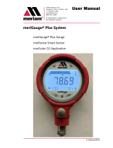
LFE Dimensions

18
LFE Dimensions
/