
Kramer Electronics, Ltd.
USER MANUAL
Models:
VS-626
, 6x6 Video / Audio Matrix Switcher
VS-828
, 8x8 Video / Audio Matrix Switcher

Contents
i
Contents
1
Introduction 1
2
Getting Started 1
2.1
Quick Start 1
3
Overview 3
4
Your VS-626 (VS-828) Video Audio Matrix Switcher 4
5
Installing on a Rack 8
6
Connecting the VS-828 Video / Audio Matrix Switcher 9
6.1
Setting the Dipswitches 11
6.1.1
SELF ADDRESS Dipswitches 11
6.1.2
Setting Connection Dipswitches 12
6.2
Controlling via RS-232 (for example, using a PC) 12
6.3
Controlling via RS-232 and RS-485 13
6.4
RGB/YUV Switching with RS-232 (PC Control) 14
7
Operating VS-828 Matrix Switcher 16
7.1
Displaying Unit Characteristics 16
7.2
Selecting and Connecting an Output and/or Input 16
7.3
Choosing the Audio-Follow-Video or Breakaway Option 17
7.3.1
Setting the Audio-Follow-Video Option 17
7.3.2
Setting the Breakaway Option 17
7.4
Storing/Recalling Input/Output Configurations 17
7.4.1
Storing an Input/Output Configuration 17
7.4.2
Recalling an Input/Output Configuration 18
7.4.3
Deleting an Input/Output Configuration 18
7.5
Resetting the Machine 18
8
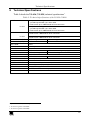
Technical Specifications 19
9
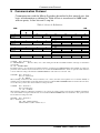
Communication Protocol 20
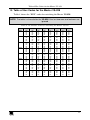
10
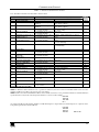
Table of Hex Codes for the Master VS-828 23
Figures
Figure 1: VS-626 6x6 Video / Audio Matrix Switcher 5
Figure 2: VS-828 8x8 Video / Audio Matrix Switcher 6
Figure 3: Connecting the Video Sources and Acceptors to the Rear Panel 10
Figure 4: VS-626 (VS-828) Dipswitch Configuration 11
Figure 5: Connecting a PC without using a Null-modem Adapter 12
Figure 6: RS-232 and RS-485 Operation 13
Figure 7: RGB Switching with RS-232 control via a PC 15

Contents
KRAMER: SIMPLE CREATIVE TECHNOLOGY
ii
Tables
Table 1: Front Panel VS-626 6x6 (VS-828 8x8) Video / Audio Matrix Switcher Features 7
Table 2: Rear Panel VS-626 6x6 (VS-828 8x8) Video / Audio Matrix Switcher Features 7
Table 3: Dipswitch Settings 11
Table 4: Self Address Dipswitch Settings 11
Table 5: Technical Specifications of the VS-626 / VS828 19
Table 6: Protocol Definitions 20
Table 7: Protocol Instruction Codes 21
Table 8: VS-828 Hex Codes for Switching the Master VS-828 23

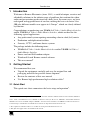
Introduction
1
1 Introduction
Welcome to Kramer Electronics (since 1981): a world of unique, creative and
affordable solutions to the infinite range of problems that confront the video,
audio and presentation professional on a daily basis. In recent years, we have
redesigned and upgraded most of our line, making the best even better! Our
500-plus different models now appear in 8 Groups
1
, which are clearly defined
by function.
Congratulations on purchasing your VS-626 6x6 Video / Audio Matrix Switcher
and/or VS-828 8x8 Video / Audio Matrix Switcher, which are ideal for the
following typical applications:
Any professional system requiring outstanding value in a 6x6 (8x8) matrix
Production and duplication facilities
Security, CCTV, and home theater systems
The package includes the following items:
VS-626 6x6 Video / Audio Matrix Switcher and/or VS-828 8x8 Video /
Audio Matrix Switcher
Power cord and Null-modem adapter
Windows®-based Kramer control software
This user manual
2
2 Getting Started
We recommend that you:
Unpack the equipment carefully and save the original box and
packaging materials for possible future shipment
Review the contents of this user manual
Use Kramer high performance high resolution cables
3
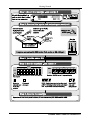
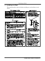
2.1 Quick Start
This quick start chart summarizes the basic setup and operation
4
:
1 GROUP 1: Distribution Amplifiers; GROUP 2: Video and Audio Switchers, Matrix Switchers and Controllers; GROUP 3:
Video, Audio, VGA/XGA Processors; GROUP 4: Interfaces and Sync Processors; GROUP 5: Twisted Pair Interfaces;
GROUP 6: Accessories and Rack Adapters; GROUP 7: Scan Converters and Scalers; and GROUP 8: Cables and Connectors
2 Download up-to-date Kramer user manuals from our Web site: http://www.kramerelectronics.com
3 The complete list of Kramer cables is on our Web site at http://www.kramerelectronics.com
4 This quick start applies both to theVS-626 and the VS-828

Getting Started
KRAMER: SIMPLE CREATIVE TECHNOLOGY
2

Overview
3
3 Overview
The high performance VS-626 (VS-828) is a true vertical interval Video /
Audio Matrix Switcher, letting you route any input to any or all of the outputs
simultaneously.
The VS-626 (VS-828) includes:
A bandwidth of 100MHz that ensures transparency even in the most
critical applications
6 (8) input and 6 (8) output button selectors
8 preset memory locations for quick access to common configurations
1
Audio-follow-video or audio breakaway option (to switch audio
independently from video)
A unique vertical and horizontal sync-pulse solution
Glitch-free transitions, which are produced when sources share a
common reference sync, as switching occurs during the vertical interval
2
An external Sync/Genlock input that may be programmed to switch
according to the timing of either this input or of source number 1
You can use the RC-IR2 IR transmitter to control the machine via the built-in
IR receiver on the front panel or, instead, via an optional external IR
receiver
3
. The external IR receiver can be located 15 meters away from the
machine. This distance can be extended to up to 60 meters when used with
three extension cables
4
.
Before using the external IR receiver, be sure to arrange for your Kramer
dealer to insert an internal IR connection cable
5
, which is required so that the
REMOTE IR 3.5mm connector can be used. Connect the external IRreceiver
to the REMOTE IR 3.5mm connector.
1 On the VS-626, 8 preset memory locations are available via RS-232
2 When one video signal replaces another video signal, the switching process causes a random interruption in the first video
signal (in the middle of a frame) and a random entrance into the second video signal (also in the middle of a frame). The
result is a visible jump in the edited tape. This deteriorates when the tape is copied, and the disturbance on playback is more
serious. Avoid this by switching at a very specific point during the vertical interval, allowing smooth replacement of a whole
frame by a second whole frame as long as the video sources are Genlocked to each other
3 P/N: 95-0104050
4 P/N: 95-0103050
5 P/N: 505-70434010-S

Your VS-626 (VS-828) Video Audio Matrix Switcher
KRAMER: SIMPLE CREATIVE TECHNOLOGY
4
Control the VS-626 (VS-828) using the front panel buttons, or remotely via
the Kramer RC-IR2 Infra-Red Remote Control Transmitter, or via an
external remote IR receiver (optional), or via RS-232 or RS-485 serial
commands transmitted by a touch screen system, PC, or other serial controller
The VS-626 (VS-828) is dependable, rugged and fits into two vertical spaces
(2U) of a standard 19" rack. To achieve the best performance:
Connect only good quality connection cables, thus avoiding
interference, deterioration in signal quality due to poor matching, and
elevated noise levels (often associated with low quality cables)
Avoid interference from neighboring electrical appliances and position your
Kramer VS-626 (VS-828) away from moisture, excessive sunlight and dust
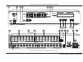
4 Your VS-626 (VS-828) Video Audio Matrix Switcher
Figure 1 illustrates the VS-626 and Figure 2 illustrates the VS-828. Table 1 and
Table 2 define the front and rear panels of the VS-626 (VS-828), respectively.

Your VS-626 (VS-828) Video Audio Matrix Switcher
5
Figure 1: VS-626 6x6 Video / Audio Matrix Switcher

Your VS-626 (VS-828) Video Audio Matrix Switcher
KRAMER: SIMPLE CREATIVE TECHNOLOGY
6
Figure 2: VS-828 8x8 Video / Audio Matrix Switcher

Your VS-626 (VS-828) Video Audio Matrix Switcher
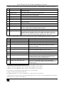
7
Table 1: Front Panel VS-626 6x6 (VS-828 8x8) Video / Audio Matrix Switcher Features
# Feature Function
1 IR Receiver The red LED is illuminated when receiving signals from the infra-red remote
control transmitter
2 POWER Switch Illuminated switch for turning the unit ON or OFF
3 OFF Button An OFF-OUT combination disconnects that output from the inputs; an OFF-ALL
combination disconnects all the outputs
4 ALL Button Pressing ALL followed by an INPUT button, connects that input to all outputs
1
5 OUTPUT Buttons Select the output to which the input is switched
6 INPUT Buttons Select the input to switch to the output
7 7-segment Display Displays the selected audio
2
or video
3
input switched to the output (marked
above each input)
8 VIDEO Button When pressed button is illuminated and all actions relate to video
9 AUDIO Button When pressed button is illuminated and all actions relate to audio
10 AFV Button When pressed button is illuminated and all actions relate to video and audio
channels. Audio channels follow the video channels
11 STO (STORE) Button Pressing STO followed by an output button stores the current setting
4
12 RCL (RECALL) Button
Pressing the RCL button and the corresponding OUTPUT key recalls a
setup from the non-volatile memory. The stored status blinks. Pressing a
different OUTPUT button lets you view
5
another setup. After making your
choice, pressing the RCL button again implements the new status
Table 2: Rear Panel VS-626 6x6 (VS-828 8x8) Video / Audio Matrix Switcher Features
# Feature Function
13 EXT. SYNC BNC Connector Connects to the external SYNC source
14 AUDIO INPUTS RCA Connectors Connect to the audio sources
15 VIDEO INPUTS BNC Connectors Connect to the video sources (from 1 to 6 / 8)
16 SYNC Source Selector Button Pushing in selects the (EXT) external sync source on the SYNC
connector; releasing selects the (IN 1) internal sync on the
VIDEO IN 1 connector
17 AUDIO OUTPUTS RCA Connectors Connect to the audio acceptors
18 VIDEO OUTPUTS BNC Connectors
6
Connect to the video acceptors (from 1 to 6 / 8)
19 RS-485 Connector RS-485 port on detachable terminal block
20 RS-232 DB 9F Connector Connects to the PC or other Serial Controller
21 Setup Dipswitches DIP 1, 2, and 3 for machine SELF ADDRESS #; DIP 4 for
RS-485 termination, DIP 5 for reply from switcher to PC,
DIP 8 for RS-232 / RS-485 communication
22 Power Connector with Fuse AC connector enabling power supply to the unit
23 REMOTE IR 3.5mm Mini Jack Connect to an external IR receiver unit for controlling the
machine via an IR remote controller (instead of using the front
panel IR receiver)
7
1 For example, press ALL and then Input button # 2 to connect input # 2 to all the outputs
2 When the Audio button illuminates, that is, when the audio breakaway mode is selected
3 When the Video button illuminates, that is, when the video breakaway mode is selected
4 For example, press STO and then the Output button # 3 to store in Setup # 3
5 Only view, nothing is implemented at this stage
6 For RGBS applications, one of the sync channels (H or V) may be used for the S channel
7 Optional. Can be used instead of the front panel (built-in) IR receiver to remotely control the VS-626/VS-828 (only if the
internal IR connection cable has been installed)

Installing on a Rack
KRAMER: SIMPLE CREATIVE TECHNOLOGY
8
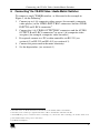
5 Installing on a Rack
This section describes what to do before installing on a rack and how to rack
mount.

Connecting the VS-828 Video / Audio Matrix Switcher
9
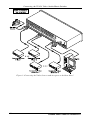
6 Connecting
1
the VS-828 Video / Audio Matrix Switcher
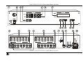
To connect a single
2
VS-828 switcher, as illustrated in the example in
Figure 3, do the following
3
:
1. Connect up to 8 (6) composite video sources (for example, composite
video players) to the VIDEO INPUT BNC connectors and the AUDIO
INPUT R and L RCA connectors
4
.
2. Connect the 8 (6) VIDEO OUTPUT BNC connectors and the AUDIO
OUTPUT R and L RCA connectors
4
to up to 8 (6) composite video
acceptors (for example, composite video recorders).
3. If required, connect to a PC or other controller via RS-232 (see
section 6.2) or RS-232 and RS-485 (see section 6.3).
4. Connect the power cord to the mains electricity
4
.
5. Set the dipswitches (see section 6.1).
1 From this section on, all the information is relevant also to the VS-626, unless noted otherwise
2 Note that you can connect up to eight VS-828 units to a PC or other RS-232 or RS-485 controller
3 Switch OFF the power on each device before connecting it to your VS-828. After connecting your VS-828, switch on its
power and then switch on the power on each device
4 Not illustrated in Figure 3

Connecting the VS-828 Video / Audio Matrix Switcher
KRAMER: SIMPLE CREATIVE TECHNOLOGY
10
Figure 3: Connecting the Video Sources and Acceptors to the Rear Panel

Connecting the VS-828 Video / Audio Matrix Switcher
11
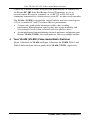
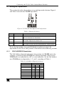
6.1 Setting the Dipswitches
This section describes the machine set-up and dipswitch selection. Figure 4
and Table 3 describe the VS-828 dipswitches.
1
2
4
5
8
3
Figure 4: VS-626 (VS-828) Dipswitch Configuration
Table 3: Dipswitch Settings
DIPS Function Description
1, 2, 3 Self Address Determines the machine number
4 RS-485 Term ON for RS-485 Line Termination
OFF for no RS-485 Line Termination
5 Reply ON enables reply from the switcher to PC
OFF disables reply from the switcher to PC
6, 7 Reserved OFF
8 RS-232\RS-485 ON enables RS-232 communication between the switcher and PC
OFF enables RS-485 communication between the switcher and PC
To set the dipswitches, use a small flathead screwdriver to move the
dipswitches to the ON or OFF position as described in the following sections.
6.1.1 SELF ADDRESS Dipswitches
The Self Address dipswitch determines the position of a VS-828 unit in the
sequence, specifying which VS-828 unit is being controlled, when several
VS-828 units are controlled by a PC or serial controller. Set the Self Address
on a VS-828 unit via dipswitches 1, 2, and 3, according to Table 4.
Table 4: Self Address Dipswitch Settings
Self Address DIPs
3 2 1
1
Master
ON ON ON
2 ON ON OFF
3 ON OFF ON
4 ON OFF OFF
5 OFF ON ON
6 OFF ON OFF
7 OFF OFF ON
8 OFF OFF OFF

Connecting the VS-828 Video / Audio Matrix Switcher
KRAMER: SIMPLE CREATIVE TECHNOLOGY
12
Up to 8 Matrix Switchers may be cascaded for control via a single port by
configuring one Matrix Switcher as a Master (Self Address = 1)
1
, while all
the others are assigned as Slave Matrix Switchers or an ID other than "1".
6.1.2 Setting Connection Dipswitches
When connecting a PC via the RS-232, set dipswitch # 8 to ON. When
connecting a PC via the RS-485, set dipswitch # 8 to OFF.
Dipswitch # 5 enables or disables Reply from the Matrix Switcher to the PC.
In some applications, it may be desirable for some machines not to reply to
instructions received on the RS-232 and RS-485 ports. If so, set the Reply
dipswitch to OFF.
In the case of interconnection between more than two RS-485 receivers-
transmitters (including PC), the termination resistor must be disconnected on
all the devices, except for the first (usually the PC) and last units on the
communication line. Dipswitch # 4 connects or disconnects the termination
resistor.
6.2 Controlling via RS-232 (for example, using a PC)
You can connect a PC (or other controller) to the VS-828 via the RS-232 port.
To connect using the Null-modem adapter provided with the machine
(recommended method):
Connect the RS-232 DB9 rear panel port on the VS-828 to the
Null-modem adapter and connect the Null-modem adapter with a
9-wire flat cable to the RS-232 DB9 port on your PC
To connect without using a Null-modem adapter:
Connect the RS-232 DB9 port on your PC to the RS-232 DB9 rear
panel port on the VS-828, as Figure 5 illustrates
Female DB9 (From PC)
PIN 4 Connected to PIN 6
PINS 8, 7, 1 Connected together
If a Shielded cable is used, connect the shield to PIN 5
PIN 5 Connected to PIN 5 (Ground)
PIN 3 Connected to PIN 2
PIN 2 Connected to PIN 3
Male DB9
Figure 5: Connecting a PC without using a Null-modem Adapter
1 The default is for Master (Self Address=1) and this is the recommended setting for a single machine

Connecting the VS-828 Video / Audio Matrix Switcher
13
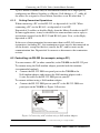
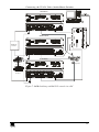
6.3 Controlling via RS-232 and RS-485
You can control up to eight single VS-828 units with control from a PC via
RS-232 (see section 6.2) and RS-485 as illustrated in Figure 6.
To control via RS-232 and RS-485, do as follows:
1. Connect the video sources and acceptors, the appropriate audio sources
and acceptors, and the power cord to each VS-828 unit.
2. On each VS-828 unit, set the Self Address dipswitches, as required
1
(see
Table 4).
3. Connect the RS-232 port on the first unit to the PC
2
.
4. Interconnect the RS-485 ports on all the VS-828 units: from the RS-485
port on the first VS-828 unit, to the RS-485 port on the second VS-828
unit, and so on – up to the RS-485 port on the last unit.
5. Terminate the RS-485 line as described in section 6.1.2.
Self Address = 1 (Master)
Self Address = 3
Figure 6: RS-232 and RS-485 Operation
1 The first unit (the master) will be set to Self Address = 1
2 As in section 6.2

Connecting the VS-828 Video / Audio Matrix Switcher
KRAMER: SIMPLE CREATIVE TECHNOLOGY
14
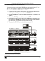
6.4 RGB/YUV Switching with RS-232 (PC Control)
Figure 7 describes a typical component video/RGB setup where every video
signal is composed of three sub signals (components), which should be
switched together (also valid for YUV components).
For RS-232 control of the component matrix switcher, an additional piece of
equipment would be required. Since RS-232 can only be used for control
between 2 pieces of equipment (e.g. a PC and a switcher), we need a method
of “distributing” the RS-232 to all 3 machines. The Kramer VP-14 “RS-232
Port Extender” is designed for this purpose.
Perform the following steps (as necessary):
1. Connect the RGB sources to the VIDEO INPUTS connectors of the
Matrix Switchers, connecting the “R” components to first Matrix
Switcher, “G” to the second, and “B” to the third. Make sure that each
component of a video source is connected to the same input number on
all three switchers.
2. Similarly, connect the RGB acceptors to the VIDEO OUTPUTS
connectors of the three Matrix Switchers.
3. If the video sources are synchronized, and vertical interval switching is
desired, connect sync sources to all 3 machines, and select to work with
“Ext. Sync” (selector switch pressed in).
4. Assign all 3 machines as Self Address # 1 (see Table 4).
5. Set dipswitch # 5 (Reply) of the first machine to ON. Set to OFF for the
other machines.
6. Set dipswitch # 8 of all the machines to ON (RS-232 communication
between switchers and external controller).
7. Connect the serial port of the PC to a port on the VP-14, and connect
each switcher to a VP-14 port. Configure the dipswitches of the VP-14
for the 4 ports, which were connected.
8. Operate the Matrix Switchers, PC, VP-14, RGB sources and RGB
acceptors.
9. The inputs can now be switched to the outputs. This is done via the front
panel switches of the first switcher, and/or via the PC.

Connecting the VS-828 Video / Audio Matrix Switcher
15
RED Matrix
Controlling PC
Data
Projector
RGB
Source
Genlock
Source
Other RGB
Source
BLUE Matrix
GREEN Matrix
Figure 7: RGB Switching with RS-232 control via a PC

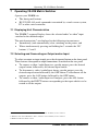
Operating VS-828 Matrix Switcher
KRAMER: SIMPLE CREATIVE TECHNOLOGY
16
7 Operating VS-828 Matrix Switcher
Operate your VS-828 via:
The front panel buttons
RS-232/ RS-485 serial commands transmitted by a touch screen system,
PC or other serial controller
7.1 Displaying Unit Characteristics
The VS-828 7-segment Display shows the selected audio
1
or video
2
input
switched to the marked output
The unit characteristics
3
are displayed in the following circumstances:
Immediately (and automatically) after switching on the power; and
When simultaneously pressing and holding for 3 seconds the “IN”
buttons 1, 2 and 3
7.2 Selecting and Connecting an Output and/or Input
To select an output or input simply press the designated button on the front panel.
These buttons correspond to output connections as marked on the rear panel.
To connect a video / audio Input to a specific output, press the desired
output button, followed by the desired input button
To disconnect a video / audio Input from a specific output, press the
desired output button followed by the OFF button. To disconnect all the
outputs, press the ALL button, followed by the OFF button
To connect a video / audio Input to all outputs, press the ALL button
followed by the INPUT button corresponding to the input which is to be
routed to all the outputs
1 When the Audio button illuminates, that is, when the audio breakaway mode is selected
2 When the Video button illuminates, that is, when the video breakaway mode is selected
3 Machine model and software version

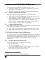
Operating VS-828 Matrix Switcher
17
7.3 Choosing the Audio-Follow-Video or Breakaway Option
You can switch stereo audio signals in one of two ways, either:
Audio-follow-video (AFV), in which all operations relate to both the
video and the audio channels; or
Breakaway, in which video and audio channels switch independently
7.3.1 Setting the Audio-Follow-Video Option
To set the Audio-follow-video (AFV) option, press the AFV button:
If the AUDIO and VIDEO configurations are the same, then the AFV
button illuminates. The audio will follow the video
If the AUDIO differs from the VIDEO, then the AFV button will blink.
Also, the audio outputs, that need to be changed, will blink
1
in the
INPUT STATUS 7-segment display. Press the AFV button again
2
. The
audio will follow the video, and the AFV illuminates.
7.3.2 Setting the Breakaway Option
To set the Breakaway option, press either the AUDIO (for audio control only)
or the VIDEO (for video control only) button.
If the AUDIO button illuminates, switching operations relate to Audio
If the VIDEO button illuminates, switching operations relate to Video
7.4 Storing/Recalling Input/Output Configurations
You can store and recall up to 8 (6) input/output configurations (or setups) in
non-volatile memory, using the INPUT SELECTOR buttons 1 to 8 (6). The
8 (6) input/output configurations also include the relevant audio-follow-video /
breakaway option definition, the video configurations and the audio
configurations.
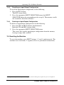
7.4.1 Storing an Input/Output Configuration
To store the current status in memory, do the following:
1. Press the STO button.
The STO button blinks.
2. Press one of the INPUT SELECTOR buttons from 1 to 8 (6). This will
be the setup # in which the current status is stored.
The memory stores the data at that reference.
1 Warning that you are about to modify the audio configuration for AFV operation
2 Failure to press the AFV button within one minute (the Timeout) will abort the action
Page is loading ...
Page is loading ...
Page is loading ...
Page is loading ...
Page is loading ...
Page is loading ...
Page is loading ...
Page is loading ...
-
 1
1
-
 2
2
-
 3
3
-
 4
4
-
 5
5
-
 6
6
-
 7
7
-
 8
8
-
 9
9
-
 10
10
-
 11
11
-
 12
12
-
 13
13
-
 14
14
-
 15
15
-
 16
16
-
 17
17
-
 18
18
-
 19
19
-
 20
20
-
 21
21
-
 22
22
-
 23
23
-
 24
24
-
 25
25
-
 26
26
-
 27
27
-
 28
28


Ask a question and I''ll find the answer in the document
Finding information in a document is now easier with AI
Related papers
Other documents
-
Kramer Electronics VP-88K User manual
-
-
-
-
-
-
-
-
Comprehensive Video CVG-606xl User manual
-