Mira Myline Installation & User Guide
- Category
- Sanitary ware
- Type
- Installation & User Guide
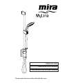
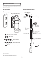
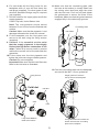
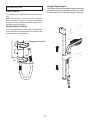
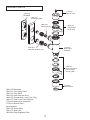
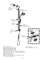
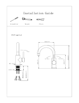
Mira Myline is an exposed valve thermostatic mixer with an integral slidebar and hose to a 360-degree showerhead. It features separate flow and temperature controls, an adjustable maximum temperature stop for safety, and inlet filters to protect the thermostatic mechanism. Suitable for domestic, light commercial, healthcare, and heavy commercial applications, the Mira Myline provides a safe and controlled showering experience.
Mira Myline is an exposed valve thermostatic mixer with an integral slidebar and hose to a 360-degree showerhead. It features separate flow and temperature controls, an adjustable maximum temperature stop for safety, and inlet filters to protect the thermostatic mechanism. Suitable for domestic, light commercial, healthcare, and heavy commercial applications, the Mira Myline provides a safe and controlled showering experience.


-
 1
1
-
 2
2
-
 3
3
-
 4
4
-
 5
5
-
 6
6
-
 7
7
-
 8
8
-
 9
9
-
 10
10
-
 11
11
-
 12
12
-
 13
13
-
 14
14
-
 15
15
-
 16
16
-
 17
17
-
 18
18
-
 19
19
-
 20
20


Mira Myline Installation & User Guide
- Category
- Sanitary ware
- Type
- Installation & User Guide
Mira Myline is an exposed valve thermostatic mixer with an integral slidebar and hose to a 360-degree showerhead. It features separate flow and temperature controls, an adjustable maximum temperature stop for safety, and inlet filters to protect the thermostatic mechanism. Suitable for domestic, light commercial, healthcare, and heavy commercial applications, the Mira Myline provides a safe and controlled showering experience.
Ask a question and I''ll find the answer in the document
Finding information in a document is now easier with AI
Related papers
-
Mira VERVE Spares Guide
-
-
-
-
-
-
-
-
-
Other documents
-
Aquasana AQ-2100W Installation guide
-
 Body-Solid PUB30 Owner's manual
-
ALFI BRAND RAIN24R-PSS Installation guide
-
-
COMPANION COMP478 Owner's manual
-
 Boyel Living RB0710 Installation guide
-
Glacier Bay Tidal Installation guide
-
 CREA Bar Sink Faucet Crea Stainless Steel Farmhouse Bathroom Lavatory Sink Faucet Mixer,Small Kitchen Faucet Tap Brushed Nickel User guide
-
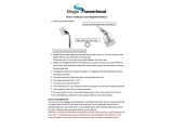 MagicShowerhead SH2030N2 Installation guide
-
Allied Brass FT-26-BKM Installation guide


