Rikon Power Tools 62-100 Owner's manual
- Category
- Power tools
- Type
- Owner's manual

Air Filtration System
Model: 6-00
Owner’s Manual
For more information:
www.rikontools.com or [email protected]
For Parts or Questions:
[email protected] or 877-884-5167
Record the serial number and date of purchase
in your manual for future reference.
Serial number:
Date of purchase:
Part # 6-00M1

Safety Warning
IMPORTANT! Safety is the single most important consideration in the operation of this equipment. The following
instructions must be followed at all times.
7KHUHDUHFHUWDLQDSSOLFDWLRQVIRUZKLFKWKLVWRROZDVGHVLJQHG:HVWURQJO\UHFRPPHQGWKDWWKLVWRROQRWEHPRGL¿HGDQG
or used for any other application other than that for which it was designed. If you have any questions about its application,
do not use the tool until you have contacted us and we have advised you.
General Safety Warnings
KNOW YOUR POWER TOOL. Read the owner’s manual carefully. Learn the tool’s applications, work
FDSDELOLWLHVDQGLWVVSHFL¿FSRWHQWLDOKD]DUGV
ALWAYS KEEP VISITORS AWAY FROM RUNNING MACHINES.
All visitors should be kept a safe distance from the work area.
ALWAYS MAKE THE WORKSHOP CHILDPROOF.
Childproof with padlocks, master switches, or by removing starter keys.
NEVER OPERATE A TOOL WHILE UNDER THE INFLUENCE OF DRUGS,
MEDICATION, OR ALCOHOL.
ALWAYS WEAR PROPER APPAREL.
Never wear loose clothing or jewelry that might get caught in moving parts. Rubber-soled footwear is
recommended for the best footing.
ALWAYS USE SAFETY GLASSES AND WEAR HEARING PROTECTION.
Also use a face or dust mask if the cutting operation is dusty.
NEVER OVERREACH.
Keep your proper footing and balance at all times.
ALWAYS GROUND ALL TOOLS.
If your tool is equipped with a three-pronged plug, you must plug it into a three-hole electric receptacle.
If you use an adapter to accommodate a two-pronged receptacle, you must attach the adapter plug to a
known ground. Never remove the third prong of the plug.
ALWAYS AVOID DANGEROUS ENVIRONMENTS.
Never use power tools in damp or wet locations. Keep your work area well lighted and clear of clutter.
ALWAYS REMOVE THE ADJUSTING KEYS AND WRENCHES FROM TOOLS AFTER USE.
Form the habit of checking to see that keys and adjusting wrenches are removed from the tool before
turning it on.
ALWAYS KEEP YOUR WORK AREA CLEAN. Cluttered areas and benches invite accidents.
NEVER STAND ON TOOLS.
Serious injury could occur if the tool is tipped or if the cutting tool is accidentally
2

SAVE THESE INSTRUCTIONS.
Refer to them often.
3
California Proposition 65 Warning
WARNING: Some dust created by power sanding, sawing, grinding, drilling, and other construction activities contains
chemicals known to the State of California to cause cancer and birth defects or other reproductive harm.Your risk from
exposure to these chemicals varies, depending on how often you do this type of work. To reduce your exposure, work in
DZHOOYHQWLODWHGDUHDDQGZLWKDSSURYHGVDIHW\HTXLSPHQWVXFKDVGXVWPDVNVWKDWDUHVSHFLDOO\GHVLJQHGWR¿OWHURXW
microscopic particles.
For more detailed information about California Propostion 65 log onto rikontools.com.
ALWAYS CHECK FOR DAMAGED PARTS.
Before initial or continual use of the tool, a guard or other part that is damaged should be checked to
assure that it will operate properly and perform its intended function. Check for alignment of moving
parts, binding of moving parts, breakage of parts, mounting, and any other conditions that may affect its
operation. A guard or other damaged parts should immediately be properly repaired or replaced.
ALWAYS DISCONNECT TOOLS.
Disconnect tools before servicing and when changing accessories such as blades, bits, and cutters.
ALWAYS AVOID ACCIDENTAL STARTING.
Make sure switch is in “OFF” position before plugging in cord.
NEVER LEAVE TOOLS RUNNING UNATTENDED.
Special Safety Rules For Dust Collection
1.Do not operate this machine until you have read all of the following instructions.
2.Do not attempt to operate this machine until it is completely assembled.
3. Do not turn ON this machine if any pieces are missing.
,I\RXDUHQRWIDPLOLDUZLWKWKHRSHUDWLRQRIWKHPDFKLQHREWDLQDVVLVWDQFHIURPDTXDOL¿HG
person.
5.It is highly recommended that this machine be placed on a level surface.
6.Always wear protective eyewear prior to operating this machine.
'RQRWRSHUDWHWKLVPDFKLQHLI\RXDUHXQGHUWKHLQÀXHQFHRIGUXJVDQGRUDOFRKRO
8.Remove all jewelry prior to operating this machine.
9.Do not wear any gloves while operating this machine.
10.Always make sure the power switch is in the OFF position prior to plugging in the machine.
11. Always make sure the power switch is in the OFF position when doing any assembly or setup
operation.
12.Always wear a dust mask when cleaning or working near a dust collector.
13.The use of any accessories or attachments not recommended may cause injury to you and
damage your machine.
14.This machine must be properly grounded.
15.Always keep your face and hands clear of moving parts such as impellors and fans.
16.Keep these instructions for future reference.

6-00
480/750/950
1/4HP, 115V, 60Hz
5 Micron Outer/1 Micron Inner
20’x20’x8’ 14x PER HR
Auto Off: 2HR/4HR/8HR
Low 61dB/Med 69dB/High 74dB
66lbs
Model Number
Air Flow (CFM)
Motor
Filtration (Micron)
Volume
Filtration Timing
Sound Level (dB)
Net Weight
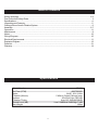
Table of Contents
Safety Warnings......................................................................................................................................2-3
Dust Collection Safety Rules....................................................................................................................... 3
Specications.........................................................................................................................................................4
Unpacking and Contents..................................................................................................................................... .5
Getting to Know Your Air Filtration System..............................................................................................................6
Assembly................................................................................................................................................................ 6-7
Operation.......................................................................................................................................8
Maintenance.........................................................................................................................................................9
Notes......................................................................................................................................................................10
Wiring Diagram......................................................................................................................................10
Electrical Requirements...................................................................................................................................11
Explosion Diagram..............................................................................................................................................12
Parts List...............................................................................................................................................................13
Warranty.................................................................................................................................................................14
Specications
4

5
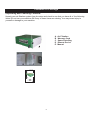
Contents of Package
Unpackyourairltrationsystemfromitscartonandchecktoseethatyouhaveallofthefollowing
items. Do not turn your machine ON if any of these items are missing. You may cause injury to
yourself or damage to your machine.
Unpacking and Checking Contents
A . Air Filtration
B . Warranty Card
C . Spare Parts Bag
D . Remote Device
E . Manual
A
B
C
D
Air Filtration System
Model: 6-00
Owner’s Manual
For more information:
www.rikontools.com or [email protected]
For Parts or Questions:
[email protected] or 877-884-5167
Record the serial number and date of purchase
in your manual for future reference.
Serial number:
Date of purchase:
Part # 61-200M1
E
A

6
The machine must not be plugged in and the power switch must be in the OFF position
until assembly is complete.
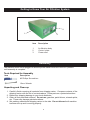
Getting to Know Your Air Filtration System
Assembly
Unpacking and Clean-up
1. Carefullynishremovingallcontentsfromshippingcarton.Comparecontentsofthe
shipping carton with the list of contents above. Place parts on a protected surface.
2. Report any shipping damage to your local distributor.
3. Clean all rust protected surfaces. Do not use; gasoline, paint thinner, mineral spirits,
etc. These may damage painted surfaces.
4. Set packing material and shipping carton to the side. Do not discard until machine
has been set up and is running properly.
Tools Required for Assembly
Item Description
#2 Phillips Screwdriver
10mm Wrench
WARNING
Item Description
1Airltrationbody
2 Control plate
3 Power cord
1
2
3

7
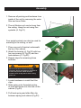
1. Remove all packing and hardware from
inside of the unit by removing the outer
lterandinnerlters.
2.Theairltrationunitcanbehungfrom
the ceiling. Hang the unit using four
eyebolts (A, Fig.01).
Four angle brackets can also be used for
mounting to the ceiling, or wall.
1. Place one end of bracket underneath
the lip of the cabinet.
2. Attach the bracket (A, Fig.02) with two
hex cap screws (B, Fig.02) and two
lock washers (C, Fig.02).
3. Repeat steps for remaining three
brackets.
Fig.01
Fig.02
Fig.03
Assembly
!
!
WARNING
Mounts must be anchored to building
structure, which will support a minimum of
at least 100 pounds. Never mount to
surfaces such as dry wall or false ceiling
grids, etc.
1.Locatehardwaretoinstallthelter
clips.
2. Slide spring onto threaded portion
of knob and screw into the side of the
cabinet (Fig.03).
3.Pullbackspringandslidelterclip
between spring and cabinet.(Fig.03).
A
A
B
C

8
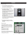
Remote Control:
1. The on/off button (Fig.04) turns the
unit on and off. Pressing this button will
start the fan on the low speed.
2. Time button (Fig.04) controls the
three different settings.
2H will light up on the back of the unit
with one press of the time button. The
airltrationsystemwilloperatefor2
hours then shut off.
4H will light up on the back of the unit
by pressing the time button twice. The
airltrationsystemwilloperatefor4
hours then shut off.
8H will light up on the back of the unit
by pressing the time button three times.
Theairltrationsystemwilloperatefor
8 hours then shut off.
Operation
3. Speed button (Fig.04) controls the
three different settings, Low, Medium
and High.
Manual Control:
Theairltrationsystemcanalsobe
operated manually. The control panel
loacted at the end of the unit has the
same functions as the remote control
above:
On/Off button (A, Fig.05)
Time button (B, Fig.05)
Speed button (A, Fig.05)
Fuse switch (C, Fig.05) will pop out in
case of overload. Wait 3-5 minutes before
resetting the fuse switch.
WARNING
Fig.04
Fig.05
A
B
C

9
Maintenance
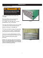
Changing the Filters
NOTE: Care should be taken when handling
soiled or contaminated lters. As certain ne
dusts can be harmful. Always wear a suitable
mask for additional protection.
Fig.06
Fig.07
Therearetwoltersthatneedtobe
changed.
Theouterltercanberemovedby
disengagingthetwoiterclips
(A,Fig.06).Pullthelterout,orusea
screwdrivertopryoutthelter.
Theinnerlter(Fig.07)cannowbepulled
outoftheunit.Theinnerltercanbe
blown out with air, or washed out.
Theltersshouldbereplaceddepending
ontheamountofusage.Cloggedlters
will reduce the amount of air circulation.
Thereisanarrowindicatingtheairow
directionontheouterlter.Makesurethe
lterisinsertedfacingtheproper
direction.
!
!
WARNING
To reduce the risk of injury disconnect the
air cleaner from the power source (unplug)
before servicing or changing lters. Failure
to comply may cause serious injury!
A

Use this section to record maintenance, service and any calls to Technical Support:
10
Notes
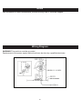
WARNING:This machine must be grounded.
Replacementofthepowersupplycableshouldonlybedonebyaqualiedelectrician.
Wiring Diagram

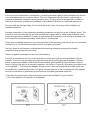
In the event of a malfunction or breakdown, grounding provides a path of least resistance for electric
current to reduce the risk of electric shock. This tool is equipped with an electric cord having an
equipment-grounding conductor and a grounding plug. The plug must be plugged into a matching
outlet that is properly installed and grounded in accordance with all local codes and ordinances.
Donotmodifytheplugprovided.Ifitwillnotttheoutlet,havetheproperoutletinstalledbya
qualiedelectrician.
Improper connection of the equipment-grounding conductor can result in a risk of electric shock. The
conductor, with insulation having an outer surface that is green with or without yellow stripes, is the
equipment-grounding conductor. If repair or replacement of the electric cord or plug is necessary, do
not connect the equipment-grounding conductor to a live terminal.
Checkwithaqualiedelectricianorservicepersonnelifthegroundinginstructionsarenotcompletely
understood, or if in doubt as to whether the tool is properly grounded.
Use only three wire extension cords that have three-prong grounding plugs and three-pole
receptacles that accept the tool’s plug.*
Repair or replace a damaged or worn cord immediately.
This tool is intended for use on a circuit that has an outlet that looks the one illustrated in Figure
A below. The tool has a grounding plug that looks like the grounding plug as illustrated in Figure A
below. A temporary adapter, which locks like the adapter as illustrated in Figure B below, may be
used to connect this plug to a two-pole receptacle, as shown in Figure B if a properly grounded outlet
is not available.** The temporary adapter should only be used until a properly grounded outlet can
beinstalledbyaqualiedelectrician.Thegreencoloredrigidearortab,extendingfromtheadapter,
must be connected to a permanent ground such as a properly grounded outlet box.
*CanadianelectricalcodesrequireextensioncordstobecertiedSJTtypeorbetter.
** Use of an adapter in Canada is not acceptable.
Electrical Requirements
11

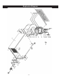
Explosion Diagram
12

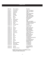
Parts List
KEY No.
Filter Board
Filter Bag
Wing Nut
Spring
Washer
Pin Plate
Body
Screw
Plug
Strain Relief
Protection
Plate Cover
Screw
Plate
Circuit Board
Screw
Nut
Fastner
Screw
+RRN
Fan Cover
Fan Asst
Fan Cover
Nut
Bolt
Screw
Clip
Screw
Fan
Motor
Screw
Nut
Bracket Washer
Motor Mat
Motor Bracket
Washer
Screw
Remote Control
-0$&
-0$&
402011
-0$&
:6+*%=
-0$&
-0$&
0;*%=
U93182300
403106
SB8
-0$&
67';*%'=
-/:
CB115A
0;*%=
0*%=
-0$&
0;*%=
0;*%=
-0$&
-/
-0$&
0*%=
0;*%=
0;*%=
-/
67';*%'=
-/
G7212646-00001G
0;*%=
0*%=
-/
-/
-/
:6+*%=
0;*%=
YKQ03
6-00-1
6-00-2
6-00-3
6-00-4
6-00-5
6-00-6
6-00-7
6-00-8
6-00-9
6-00-10
6-00-11
6-00-12
6-00-13
6-00-14
6-00-15
6-00-16
6-00-17
6-00-18
6-00-19
6-00-20
6-00-21
6-00-22
6-00-23
6-100-24
6-100-25
6-100-26
6-100-27
6-100-28
6-100-29
6-100-30
6-100-31
6-100-32
6-100-33
6-100-34
6-100-35
6-100-36
6-100-37
6-100-38
Description Part No.
NOTE: Please reference the KEY No. when
calling for replacement parts.
13

5-Year Limited Warranty
RIKON Power Tools Inc. (“Seller”) warrants to only the original retail consumer/purchaser of our
SURGXFWVWKDWHDFKSURGXFWEHIUHHIURPGHIHFWVLQPDWHULDOVDQGZRUNPDQVKLSIRUDSHULRGRI¿YH
(5) years from the date the product was purchased at retail. This warranty may not be transferred.
This warranty does not apply to defects due directly or indirectly to misuse, abuse, negligence,
accidents, repairs, alterations, lack of maintenance or normal wear and tear. Under no
circumstances will Seller be liable for incidental or consequential damages resulting from
GHIHFWLYHSURGXFWV$OORWKHUZDUUDQWLHVH[SUHVVHGRULPSOLHGZKHWKHURIPHUFKDQWDELOLW\
¿WQHVVIRUSXUSRVHRURWKHUZLVHDUHH[SUHVVO\GLVFODLPHGE\6HOOHU7KLVZDUUDQW\GRHVQRWFRYHU
products used for commercial, industrial or educational purposes.
This limited warranty does not apply to accessory items such as blades, drill bits, sanding discs or
belts and other related items.
6HOOHUVKDOOLQQRHYHQWEHOLDEOHIRUGHDWKLQMXULHVWRSHUVRQVRUSURSHUW\RUIRULQFLGHQWDO
contingent, special, or consequential damages arising from the use of our products.
7RWDNHDGYDQWDJHRIWKLVZDUUDQW\SURRIRISXUFKDVHGRFXPHQWDWLRQZKLFKLQFOXGHVGDWHRI
SXUFKDVHDQGDQH[SODQDWLRQRIWKHFRPSODLQWPXVWEHSURYLGHG
7KH6HOOHUUHVHUYHVWKHULJKWWRHIIHFWDWDQ\WLPHZLWKRXWSULRUQRWLFHWKRVHDOWHUDWLRQVWRSDUWV
¿WWLQJVDQGDFFHVVRU\HTXLSPHQWZKLFKWKH\PD\GHHPQHFHVVDU\IRUDQ\UHDVRQZKDWVRHYHU
7RWDNHDGYDQWDJHRIWKLVZDUUDQW\SOHDVH¿OORXWWKHHQFORVHGZDUUDQW\FDUGDQGVHQGLWWR
RIKON Warranty
16 Progress Rd.
Billerica, MA 01821
The card must be entirely completed in order for it to be valid. If you have any questions
please contact us at 877-884-5167 or [email protected].
Warranty
14


For more information:
16 Progress Rd
Billerica, MA 01821
877-884-5167 / 978-528-5380
www.rikontools.com
Copyright RIKON Power Tools, Inc. 2011 Printed in China 1/11
-
 1
1
-
 2
2
-
 3
3
-
 4
4
-
 5
5
-
 6
6
-
 7
7
-
 8
8
-
 9
9
-
 10
10
-
 11
11
-
 12
12
-
 13
13
-
 14
14
-
 15
15
-
 16
16


Rikon Power Tools 62-100 Owner's manual
- Category
- Power tools
- Type
- Owner's manual
Ask a question and I''ll find the answer in the document
Finding information in a document is now easier with AI
Related papers
-
Rikon Power Tools 62-450 User manual
-
-
-
-
-
-
-
-
-
Other documents
-
PowerTech AF4001 Air Filtration System Owner's manual
-
King Canada KAC-1200 User manual
-
King Industrial KAC-1400 User manual
-
-
PowerTec AF4000 Owner's manual
-
General International 10-550 M1 User guide
-
-
KUHN RIKON Corp. Drill 30-100 User manual
-
Greenworks GPW 1951 User manual
-
Jet Tools AFS-400 User manual