Page is loading ...

EN/LZT 720 0135 Uen R3A
RBS 2207
Radio Configura t ion s
Description
This document descri bes the radio configurations for RBS 2207.
TX1
dTRU
TX1
CDU-J
CDU-J
RX2
RX1
TX2
P012209A
TX2
RX3
RX4
RX2
RX1
TX/
RXA
DPX LNA DPX
TMA
(optional)
X
X
1
2
TX/
RXA
DPX LNA DPX
TMA
(optional)
XX
1
2
RXB
RXB
DPX
DPX
CELL 1
CELL 2
CELL 1
CELL 2
LNA
LNA
TX1
RX2
RX1
TX2
DPX LNA DPX
TMA
(optional)
X
X
1
2
DPX LNA DPX
TMA
(optional)
X
X
1
2
DPX
DPX
LNA
LNA
1 = Antenna Reference Point without TMA
2 = Antenna Reference Point with TMA
E
1 (14)

RBS 22 07Radio Configurations
Contents
1 Introduction 3
1.1 Mobile Telephon e System 3
1.2 Radio Base Statio n 4
2 References 4
3 Definitions 4
3.1 Cabin et Types 6
4 Frequency Bands 6
5 Basic Configurations 6
5.1 dTRU Topology 7
5.2 CDU-J Configurations 9
6 Site Cell Configurations (SCC) 12
6.1 Single Band Con figurations 12
6.2 Dual Band Configurati on 13
6.3 Mixing CDU-G and CDU-J 14
6.4 RX Cables 14
6.5 SW Power Boos t Configurations with CDU-J 14
2 (14)
EN
/LZT 720 0135 Uen R3A

RBS 22 07 Radio Configurations
1 Introduction
The radio configurations described are valid for RBS 2207, equipped with a
maximum of three dTRUs/s ix TRXs per cabinet. The descriptions include basic
configurations and site cell configurations.
1.1 Mobile Telephone System
P007534B
PSTN
SS
OSS
BSS
BSC
BTS
RBS 2000
SS Switching System
OSS Operation Support System
BSS Base Station System
BSC Base Station Controller
RBS Radio Base Station
BTS Base Transceiver Station
PSTN Public Switched Telephone Network
Figure 1 RBS 2000 in the Eri csson GSM system
The Base Station System (BSS) contains two functional entities; the Base
Station Controller (BSC) and the Ba se Transceiver Station (BTS).
The BSC handles radio-related functions such as handover, management of
the ra dio network resources, an d cell configuration data. It al so con trols radio
frequency power levels in RBSs and MSs.
The BTS is a network component which serv es one cell, and is controlled by
the BSC. The BTS consists of the radio transceivers and all the digital signal
processing equipment. RBS 2000 contains equipment for one to three BTSs.
3 (14)
EN/LZT 720 0135 Uen R3A

RBS 22 07Radio Configurations
Figure 2 An example of an RBS 2000 s ervicing a three-cell site
1.2 Radio Base Stat ion
The Radio Base Station 2000 (RBS 2000) is Ericsson’s second gen eration of
RBSs, developed to meet the GSM specifications for BTSs.
2 Refe rence s
3GPP TS 45:005
Digital cellula r telecommunicati ons system (Phase 2+);
Radio transmission and reception (3GPP TS 45:005
Relea se 4).
3GPP TS 45:008
Digital cellular telecom munications system (Phase
2+); Radio subsystem link control (3 GPP TS 45:008
Relea se 4).
3 Definitions
Tower Mounted Amplifier (TMA)
The TMA compensates for signal loss in the rec eiver antenna cables, reduces
system noise and improves up link sensitivity. The TMA can consist of a duplex
filter. Duple x is the functio n that allows communication in tw o directions
(sending and rec eiving) on one channel.
The TMAs used are Dual Dup lex TMA (ddTM A).
4 (14)
E
N/LZT 720 0135 Uen R3A

RBS 22 07 Radio Configurations
Antenna Reference Point
The antenna reference point is the point where the radio signa l crosses the
RBS border, that is the connector for the antenna feeder. See the fi gure below.
Note: The TMA is inside the RBS bord er.
X
P007531A
RBS
TRX
Combining
system
+
filtering
TRX
TRX
X = Antenna reference point
Antenna
.
.
.
Figure 3 A ntenna reference point
Antenna System
The antenna system c omprises all RF transmission and reception anten nas,
directed to cover the same area or multi -casting configurations.
Base Transceiver Station (BTS)
A B TS is a unit operating on a set of frequencies in one cell.
Basic Configuration
A basic config uration is a specified set of transceivers, CDUs and (in some
cases) TMAs, connecte d to one a ntenna sys te m.
A basic configuration can be multiplied or used in combination with other basic
configurations, in order to build the necess ar y site equipment.
Radio Base Station ( RBS)
An RBS const itutes all the equipment in an Ericsson base station, and may
comprise several BTSs.
Each RBS has one DXU, wh ich consists of a maximum of six TRXs .
5 (14)
EN/LZT 720 0135 Uen R3A

RBS 22 07Radio Configurations
Site Cell Co nfiguration (SCC)
The SCC is a geograp hical concept describing how an are a around one RBS
site is divided into radio traffic areas. The following types of site are defined:
Omni-site
Radio coverage in one 360 degree sector, that is in
one are a, usin g one BTS.
2-sector site Radio coverage in two sec to rs, that is two distinct
areas, using two BTS s.
3-sector site Radio cov erage in th ree sectors, that is three distinct
areas, using three BTSs.
3.1 Cabinet Typ es
RBS 2207
Indoor cabinet with a maximum of three dTRUs/six TRXs
per cabinet
4 Frequency Bands
GSM 800 Uplink: 824 – 849 MHz
Downlink: 869 – 894 MHz
P-GSM 900 Uplink: 890 – 915 MHz
Downlink: 935 – 960 MHz
E-GSM 900 Uplink: 880 – 915 MHz
Downlink: 925 – 960 MHz
GSM 1800 Uplink: 1710 – 1785 MHz
Downlink: 1805 – 1880 MHz
GSM 1900 Uplink: 1850 – 1910 MHz
Downlink: 1930 – 1990 MHz
These frequ ency bands are supported by the configurations described in this
document.
5 Basi c Confi gura tions
The GSM 800, P-GSM 900, E-GSM 900, GSM 1 800 and GSM 190 0
configurations meet the GSM requirements, exce pt where otherwise stated.
6 (14)
E
N/LZT 720 0135 Uen R3A

RBS 22 07 Radio Configurations
The radio pe rformance of a configuration is defined at th e TX an d RX antenna
reference points at the RBS border. There is an X close to every reference
point in the following figures. The RBS border is not include d in the figures .
The equivalen t ou tput power with SW power boost (TX diversity) configured
is the original output power specified for the basic configuration, increased by
typically 3 dB (if separate TX anten nas are used). The configurations that
support SW power boost are listed in Section 6.5 on page 14.
Functional views of radio signal path s for various configurations are shown in
Figure 4 on page 8 up to and including Figure 7 on page 10. O nly components
necessary to illustrate the configu ra tion are shown.
5.1 dTRU Topol ogy
Configu ration of Hybrid Co mbiner
The dTRU can be con figured with or withou t the h ybrid comb iner, using two
cables exter nal to the dTRU, see Figure 4 on page 8.
Later versions of the dTRU do not use e xternal hybrid cables, see Figure 5 on
page 8.
RX Signals Distributed from Two P orts
The RX signals can be distributed from the R X1 and RX2 po rts to all four
receivers when both transceivers are connected to the same antenna system.
7 (14)
EN/LZT 720 0135 Uen R3A

RBS 22 07Radio Configurations
TX1
TX
TX
P011000B
HC2
TX2 TX2
RX
RX
RX
RX
RX3
RX4
TX
RX1
RX
RX
RX
RX
RX2
Hybrid
combiner
Hybrid
combiner
TX1
TX
TX
HC2
RX2
TX2
TX1+TX2
HC1
RX
RX
RX
RX
RX1
RX4
RX3
RX
RX
RX
RX
dTRU with no hybrid
combiner in use
dTRU with hybrid
combiner in use
TX1
TX
TX
HC
TX1+TX2
HC1
TX1+TX2
HC1
RX
RX
RX
RX
RX3
RX4
TX
TX
RX1
RX
RX
RX
RX
RX2
Hybrid
combiner
dTRU with no hybrid
combiner in use,
shared between 2 cells
Figure 4 dTRU w ith and witho ut Hybrid Combiner in Use
TX1
TX
TX
P012225A
TX2 TX2
RX
RX
RX
RX
RX3
RX4
TX
RX1
RX
RX
RX
RX
RX2
Hybrid
combiner
Hybrid
combiner
TX1
TX
TX
RX2
TX2
TX1+TX2
RX
RX
RX
RX
RX1
RX4
RX3
RX
RX
RX
RX
dTRU with no hybrid
combiner in use
dTRU with hybrid
combiner in use
TX1
TX
TX
TX1+TX2
TX1+TX2
RX
RX
RX
RX
RX3
RX4
TX
TX
RX1
RX
RX
RX
RX
RX2
Hybrid
combiner
dTRU with no hybrid
combiner in use,
shared between 2 cells
Figure 5 dTRUs with Internal Switch for Hybrid Com bining
8 (14)
E
N/LZT 720 0135 Uen R3A

RBS 22 07 Radio Configurations
5.2 CDU-J Configurations
This section shows different configurations using CDU-J. The same
configuration can exist us ing CD U-G but configured the same as CDU-J.
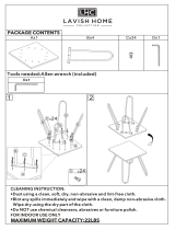
Configu ration 2x1 CDU-J without hybrid combiner
TX1
dTRU
TX1
CDU-J
CDU-J
RX2
RX1
TX2
P012209A
TX2
RX3
RX4
RX2
RX1
TX/
RXA
DPX LNA DPX
TMA
(optional)
X
X
1
2
TX/
RXA
DPX LNA DPX
TMA
(optional)
XX
1
2
RXB
RXB
DPX
DPX
CELL 1
CELL 2
CELL 1
CELL 2
LNA
LNA
TX1
RX2
RX1
TX2
DPX LNA DPX
TMA
(optional)
X
X
1
2
DPX LNA DPX
TMA
(optional)
X
X
1
2
DPX
DPX
LNA
LNA
1 = Antenna Reference Point without TMA
2 = Antenna Reference Point with TMA
Figure 6 2x1 CDU-J uncombined
Characteristics for one cell
Number of CDUs 2 (2 CDUs s upport
two sectors)
Frequency band GSM 800
P-GSM 900
E-GSM 900
9 (14)
EN/LZT 720 0135 Uen R3A

RBS 22 07Radio Configurations
Characteristics for one cell
GSM 1800
GSM 1900
Max. number of TRXs 1 (1 dTRU supports
two sectors)
Numb er of feeders 2
Numb er of a ntennas 2
Anten na configuration TX/RX + R X
TMA configuration (optional) ddTMA + ddTMA
Configuration 1x2 CDU-J with hybrid combiner
RX2
RX1
TX1 + TX2
dTRU
CDU-J
RX2
RX1
P012211A
TX/
RXA
DPX LNA DPX
TMA
(optional)
X
X
1
2
RXB
DPX LNA DPX
TMA
(optional)
XX
1
2
DPX
DPX
LNA
LNA
1 = Antenna Reference Point without TMA
2 = Antenna Reference Point with TMA
Figure 7 1x2 CDU-J uncombined
Characteristics
Numb er of CDUs 1
Frequency band GSM 800
P-GSM 900
E-GSM 900
GSM 1800
GSM 1900
Max. number of TRXs 2
10 (14)
E
N/LZT 720 0135 Uen R3A

RBS 22 07 Radio Configurations
Characteristics
Number of feeders 2
Number of antennas 2
Antenna configuration TX/RX + RX
TMA configurat ion (optional) ddTMA + ddT MA
Configu ration 1x2 CDU-J without hybrid combiner
RX2
RX1
TX1
dTRU
TX1
CDU-J
RX2
RX1
TX2
P012212A
TX2
TX/
RXA
DPX LNA DPX
TMA
(optional)
X
X
1
2
TX/
RXA
DPX LNA DPX
TMA
(optional)
XX
1
2
DPX
DPX
LNA
LNA
1 = Antenna Reference Point without TMA
2 = Antenna Reference Point with TMA
Figure 8 1x2 CDU-J uncombined
Characteristics
Number of CDUs 1
Frequency band GSM 800
P-GSM 900
E-GSM 900
GSM 1800
GSM 1900
Max. number of TRXs 2
Number of feeders 2
Number of antennas 2
Antenna configuration TX/RX + TX/RX
TMA configurat ion (optional) ddTMA + ddT MA
11 (14)
EN/LZT 720 0135 Uen R3A

RBS 22 07Radio Configurations
6 Site Cell Configura tions (SCC)
This section sho ws SCCs in one RBS. More RBSs can be combin ed to form
larger configurations at a site.
The following SCCs are supported by the RBS:
• Specified basic radio conf igurations
• The RBS with any number of dTRUs w ithin th e specifi ed range insert ed in
the specified positio n order
• CDU-G ca n exist in earlier versions of RBS 2207
6.1 Single Band Configurations
This section describes single band configurations for CDU-J.
CDU-J Single Band Configurations without Hybrid Combine r
Table 1 CDU-J configura tions for GSM 800, P-GSM 900, E-GSM 900, GSM 180 0 or GSM 1900
Max no. of TRXs No. of antennas
Cell: Cell:
No. of
cells
1 2 3 1 2 3
See:
1 2 2 Figure 7 on page 10 (config. x1)
2 2 2 2 2 Figure 7 on page 10 (config. x2)
1 1 2 2 Figure 6 on page 9 (config. x2)
3 2 2 2 2 2 2 Figure 7 on page 10 (config. x3)
1 1 2 2 2 2 Cell 1: Figure 6 on page 9
Cell 2: Figure 6 on page 9
Cell 3: Figure 7 on page 10
12 (14)
E
N/LZT 720 0135 Uen R3A

RBS 22 07 Radio Configurations
CDU-J Single Band Configurations with Hybrid Combiner
Table 2 CDU-J configura tions for GSM 800, P-GSM 900, E-GSM 900, GSM 180 0 or GSM 1900
Max no. of TRXs No. of antennas
Cell: Cell:
No. of
cells
1 2 3 1 2 3
See:
1 2 2 Figure 8 on page 11 (config. x1)
2 2 2 2 2 Figure 8 on page 11 (config. x2)
3 2 2 2 2 2 2 Figure 8 on page 11 (config. x3)
6.2 Dual Band Configuration
The following configurations can be set to 2+1, 1+2 or 1+1 each with different
frequency ba nds:
• 2 x 900 MH z + 1 x 1800 MHz (2+1)
• 1 x 900 MH z + 2x 1800 MHz ( 1+2)
The following co nf igurations is allowed for Dual band:
• GSM 800/1900
• GSM 900/1800
• GSM 800/1800
Table 3 CDU-J Configur ations for Du al Band
Max no. of TRXs No. of antennas
Cell: Cell:
No. of
cells
1 2 3 1 2 3
See:
2 2 2 2 2 Figure 7 on page 10 (config. x2)
3 2 2 2 2 2 2 Figure 7 on page 10 (config. x3)
2 2 2 2 2 Figure 8 on page 11 (config. x2)
3 2 2 2 2 2 2 Figure 8 on page 11 (config. x3)
13 (14)
EN/LZT 720 0135 Uen R3A

RBS 22 07Radio Configurations
6.3 Mixing CDU-G an d CDU-J
Mixing CDU-G and CDU-J within the same cabinet is allowed for all single b and
and dual ba nd, except for 2x1 CDU-J or CDU -G without hybrid c ombiner. See
Figure 6 on pag e 9, that is dTRU to 2 x CDU-G or 2 x CDU-J.
6.4 RX Cables
CDU-G must be cabled with QMA attenuators or the cables with build-in
attenuators. CD U-J must never be cabled with the RX cables with bu ild-in
attenuators. It must be cabled without the QMA attenuators.
6.5 SW Power Boost Configurations with CDU-J
This section does not includ e any ad ditional site cell configurations. The section
specifies w hich configurations support SW Power Boost (SPB).
A minimum of two TRXs is required in an antenna system in order to use SW
Power Boost. Separate TX antennas must be used for the two transmi tters in
an SPB configuration.
SPB with CDU-J Configurations without Hybrid Combiner
SW Power Boost is supported in all of the SCCs with CDU-G/CDU-J, specified
in Section 6 o n page 11, which fulfill the following conditions:
• The configurations do no t use hybrid combiner
• The configurations have the TRX connected to different antennas in the
same antenn a system
Ericsson AB
SE-164 80 Stockholm
Sweden
asq.us@ericsson.com
No part of this document may be reproduced in any form without
the written permission of the copyright owner.
The contents of this document are subject to revision without
noti ce due to cont inued progress in methodology, design and
manufacturing. Ericsson shall have no liability for any error or
damage of any kind result ing from th e use of this document.
© Ericsson AB 2004 — All R ights Reserved
14 (
14)
EN/LZT 720 0135 Uen R3A

EN/LZT 720 0319 Uen R3A
RBS 2106
Ant enn a Configura t ion s
Description
This document describes the a lternative antenna configurations for the RBS
2106.
P008227C
DX1 DX1 RXB DX1 RXB
Cell
A
Cell
B
Cell
C
RXB
E
1 (28)

RBS 21 06Antenna Configurations
Contents
1 Introduction 3
2 Antenna Connection Fi el d 3
3 CDU-F Antenna Connections 6
4 CDU-F Configurations 7
4.1 3x4 CDU-F Configuration 7
4.2 1x8 CDU-F Configuration 9
4.3 1x12 CDU-F Configuration 10
4.4 2x6 CDU-F Configuration 11
4.5 1x4 + 1x8 CDU-F Configuration 12
4.6 1x8 + 1x4 CDU-F Configuration 13
4.7 3x8 CDU-F Configuration 14
5 CDU-G Antenn a Connections 15
6 CDU-G Configurations 16
6.1 3x2 CDU-G and 3x4 CDU-G Con figuration 16
6.2 2x1 CDU-G Configuration 18
6.3 2x3 CDU-G Configuration 19
6.4 1x4 CDU-G with out HCU an d 1x8 CDU-G with HCU
Configuration 20
6.5 1x6 CDU-G without HCU and 1x12 CDU-G with HCU
Configuration 21
6.6 1x8 CDU-G with HCU Confi guration 22
6.7 1x12 CDU-G with HCU Configuration 23
6.8 2x6 CDU-G Configuration 24
6.9 3x8 CDU-G with HCU Confi guration 25
2 (28)
EN
/LZT 720 0319 Uen R3A

RBS 21 06 Antenna Configurations
1 Introduction
The various configurations available for the RBS 2106 are des cribed ac cording
to the following example:
P008245B
3 x 2 CDU-F
Number
of cells
Number
of TRX/cell
Type of CDU
Figure 1 C DU Confi gurat
ion Key
In the example above, the cabinet is configured for three cells, each us ing two
Transceivers (TRX). Th e to ta l number of TRXs is thus six in this case. The
Combini ng and Dis trib
ution Unit (CDU) is of the type CDU-F.
Note: If a Tower Mounted Amplifier (TMA) is used, then the bias injectors
must be installe d.
2 Antenna Connect ion Field
This s ection descr
ibes the antenna connection fields in the RBS 2106.
Antenna jumpers are connected a t the connection field sh own in the figu re
below.
Each CDU uses a set o
f standard RF wiring patterns for connec tions made
between each CDU and the antenna connection field.
3 (28)
EN/LZT 720 0319 Uen R3A

RBS 21 06Antenna Configurations
P008594D
CDU-F CDU-G
1
(x6)
A1
A2
A3
A4
A5
A6
A1
A2
A3
A4
A5
A6
A1
A2
A3
A4
A5
A6
CDU-F
CDU-F
CDU-F
CDU-G
900
CDU bus
DC in
TX1
TX2
RX1
RX2
Fault
Open
CDU-G
900
CDU bus
DC in
TX1
TX2
RX1
RX2
Fault
Open
CDU-G
900
CDU bus
DC in
TX1
TX2
RX1
RX2
Fault
Open
Figure 2 Internal Cabling b etween CDUs and Antenna Connection Field
Certain configur at ions require the use of an Ante nna Sharing Unit (ASU). In
these cases , the signal is shared between RBSs through the antenna sharing
connection fields.
The figure below provides an overview of the antenna sharing connectors and
the cabling from the ASU.
4 (28)
E
N/LZT 720 0319 Uen R3A

RBS 21 06 Antenna Configurations
Figure 3 Cabling between ASU and Antenna Sharing Connectors
5 (28)
EN/LZT 720 0319 Uen R3A

RBS 21 06Antenna Configurations
3 CDU-F Antenna Connections
The antenna connectors are located in the antenna connection field , see
Section 2 Antenna Connection Field on page 3.
The ant enna connec to rs are located on the top of the CDU, see the figures
below.
P007450E
Antenna connectors
CDU-F
Figure 4 CDU-F Layout
Figure 5 C DU-F Antenna Feeder Connectors
6 (28)
E
N/LZT 720 0319 Uen R3A
/