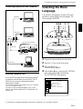
Sony Sony VPL-PS10 User manual
- Category
- Data projectors
- Type
- User manual

VPL-PX15/PX10/PS10
© 2001 Sony Corporation
4-083-534-15(1)
VPL-PX15
VPL-PX10
VPL-PS10
Operating Instructions
Mode d’emploi
Manual de instrucciones
FR
ES
LCD Data Projector
GB

2 (GB)
To prevent fire or shock hazard, do not
expose the unit to rain or moisture.
To avoid electrical shock, do not open the
cabinet. Refer servicing to qualified
personnel only.
This symbol is intended to alert the
user to the presence of uninsulated
“dangerous voltage” within the
product’s enclosure that may be of
sufficient magnitude to constitute a risk
of electric shock to persons.
This symbol is intended to alert the
user to the presence of important
operating and maintenance (servicing)
instructions in the literature
accompanying the appliance.
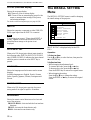
WARNING
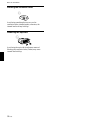
This label is located on
the rear of the Remote
Commander.
This label is located on the
rear of the Remote
Commander.
Caution
Use of controls or adjustments or performance of
procedures other than those specified herein may result in
hazardous radiation exposure.
Notes
• Do not aim the laser at people and do not look into the
laser transmitter.
• If the Remote Commander malfunctions or causes a
malfunction, consult with qualified Sony personnel. We will
exchange the Remote Commander for a new one based
on the terms of the guarantee.
For the customers in Canada
This Class A digital apparatus complies with Canadian
ICES-003.
This label is located on the
rear of the Remote
Commander.
Laser light shines out of this window.
For the customers in the USA
This equipment has been tested and found to comply with
the limits for a Class A digital device, pursuant to Part 15 of
the FCC Rules. These limits are designed to provide
reasonable protection against harmful interference when the
equipment is operated in a commercial environment. This
equipment generates, uses, and can radiate radio frequency
energy and, if not installed and used in accordance with the
instruction manual, may cause harmful interference to radio
communications. Operation of this equipment in a
residential area is likely to cause harmful interference in
which case the user will be required to correct the
interference at his own expense.
You are cautioned that any changes or modifications not
expressly approved in this manual could void your authority
to operate this equipment.
This label is located on
the rear of the Remote
Commander.
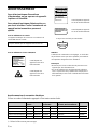
LASER RADIATION
DO NOT STARE INTO BEAM
CLASS 2 LASER PRODUCT
RAYONNEMENT LASER
NE PAS REGARDER DANS LE FAISCEAU
APPAREIL A LASER DE CLASSE 2
LASER–STRAHLING,
NICHT IN DEN STRAHL BLICKEN
LASER KLASSE 2
MAX OUTPUT : 1mW EN60825-1
WAVE LENGTH : 645nm /A11:1996
CAUTION
LASER RADIATION
DO NOT STARE INTO BEAM
WAVE LENGTH:645nm
MAX OUTPUT:1mW
CLASS II LASER PRODUCT
COMPLIES WITH DHHS 21 CFR
SUBCHAPTER J
SONY CORPORATION
6-7-35 KITASHINAGAWA
SHINAGAWA-KU, TOKYO, JAPAN
A
MANUFACTURED
AVOID EXPOSURE-
LASER RADIATION IS
EMITTED FROM THIS
APERTURE.
For the customers of the VPL-PX15/PX10

3 (GB)
For the customers in the United Kingdom
WARNING
THIS APPARATUS MUST BE EARTHED
IMPORTANT
The wires in this mains lead are coloured in accordance with
the following code:
Green-and-Yellow: Earth
Blue: Neutral
Brown: Live
As the colours of the wires in the mains lead of this
apparatus may not correspond with the coloured markings
identifying the terminals in your plug proceed as follows:
The wire which is coloured green-and-yellow must be
connected to the terminal in the plug which is marked by the
letter E or by the safety earth symbol I or coloured green
or green-and-yellow.
The wire which is coloured blue must be connected to the
terminal which is marked with the letter N or coloured black.
The wire which is coloured brown must be connected to the
terminal which is marked with the letter L or coloured red.
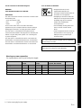
Warning on power connection
Use a proper power cord for your local power supply.
The United States, Continental UK, Ireland, Japan
Canada Europe Australia, New Zealand
Plug type VM0233 290B YP-12A COX-07 —
1)
YP332
Female end VM0089 386A YC-13B COX-02 VM0310B YC-13
Cord type SJT SJT H05VV-F H05VV-F N13237/CO-228 VCTF
Rated Voltage & Current 10A/125V 10A/125V 10A/250V 10A/250V 10A/250V 7A/125V
Safety approval UL/CSA UL/CSA VDE VDE VDE DENAN
.........................................................................................................................................................................................................
1) Use the correct plug for your country.
Voor de klanten in Nederland
• Dit apparaat bevat een vast
ingebouwde batterij die niet
vervangen hoeft te worden tijdens de
levensduur van het apparaat.
• Raadpleeg uw leverancier indien de
batterij toch vervangen moet worden.
De batterij mag alleen vervangen
worden door vakbekwaam
servicepersoneel.
• Gooi de batterij niet weg maar lever
deze in als klein chemisch afval
(KCA).
• Lever het apparaat aan het einde van
de levensduur in voor recycling, de
batterij zal dan op correcte wijze
verwerkt worden.
The socket-outlet should be installed near the equipment
and be easily accessible.
Apparaten ma kun tilkoples jordet stikkontakt.
Apparatet må kun tilkoples jordet stikkontakt.
English
GB
Page is loading ...

5 (GB)
Table of Contents
Overview
Precautions ............................................................... 7 (GB)
Features..................................................................... 8 (GB)
Location and Function of Controls......................... 9 (GB)
Front / Left Side ....................................................... 9 (GB)
Rear / Right Side / Bottom....................................... 9 (GB)
Control Panel ......................................................... 11 (GB)
Connector Panel ..................................................... 13 (GB)
Remote Commander (supplied with the
VPL-PX15/PX10)............................................. 14 (GB)
Remote Commander (supplied with the
VPL-PS10)........................................................ 16 (GB)
Setting Up and Projecting
Installing the Projector........................................... 18 (GB)
Connecting the Projector....................................... 18 (GB)
Connecting to a Computer ..................................... 18 (GB)
Connecting to a VCR or 15k RGB/Component
Equipment......................................................... 20 (GB)
Connecting to a LAN (VPL-PX15 only) ............... 21 (GB)
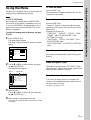
Selecting the Menu Language............................... 23 (GB)
Projecting ................................................................ 24 (GB)
Adjustments and Settings Using the Menu
Using the Menu....................................................... 27 (GB)
The PICTURE CTRL Menu ..................................... 28 (GB)
The INPUT SETTING Menu .................................... 29 (GB)
The SET SETTING Menu ........................................ 31 (GB)
The INSTALL SETTING Menu ................................ 32 (GB)
Installation
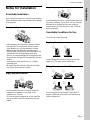
Installation Example............................................... 34 (GB)
Notes for Installation.............................................. 35 (GB)
Unsuitable Installation ........................................... 35 (GB)
Unsuitable Conditions for Use............................... 35 (GB)

6 (GB)
Maintenance
Maintenance............................................................ 37 (GB)
Replacing the Lamp ............................................... 37 (GB)
Cleaning the Air Filter ........................................... 38 (GB)
Troubleshooting ..................................................... 39 (GB)
Other
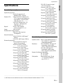
Specifications ......................................................... 41 (GB)
Index ........................................................................ 44 (GB)

7 (GB)
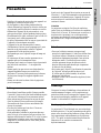
Precautions
On safety
•Check that the operating voltage of your unit is
identical with the voltage of your local power
supply.
•Should any liquid or solid object fall into the cabinet,
unplug the unit and have it checked by qualified
personnel before operating it further.
•Unplug the unit from the wall outlet if it is not to be
used for several days.
•To disconnect the cord, pull it out by the plug. Never
pull the cord itself.
•The wall outlet should be near the unit and easily
accessible.
•The unit is not disconnected to the AC power source
(mains) as long as it is connected to the wall outlet,
even if the unit itself has been turned off.
•Do not look into the lens while the lamp is on.
•Do not aim the laser at people and do not look into
the laser transmitter.
•Do not place your hand or objects near the
ventilation holes — the air coming out is hot.
•Be careful not to catch your fingers with the
adjusters when you lift up the projector. Do not push
hard on the top of the projector with the adjusters
out.
•Be sure to grasp both sides when carrying the
projector.
On illumination
•To obtain the best picture, the front of the screen
should not be exposed to direct lighting or sunlight.
•Ceiling-mounted spot lighting is recommended. Use
a cover over fluorescent lamps to avoid lowering the
contrast ratio.
•Cover any windows that face the screen with opaque
draperies.
•It is desirable to install the projector in a room where
floor and walls are not of light-reflecting material. If
the floor and walls are of reflecting material, it is
recommended that the carpet and wall paper be
changed to a dark color.
On preventing internal heat build-up
After you turn off the power with the I /
1
key on the
Remote Commander or on the control panel, do not
disconnect the unit from the wall outlet while the
cooling fan is still running.
Caution
The projector is equipped with ventilation holes
(intake) on the bottom and ventilation holes (exhaust)
on the front. Do not block or place anything near these
holes, or internal heat build-up may occur, causing
picture degradation or damage to the projector.
On cleaning
•To keep the cabinet looking new, periodically clean
it with a soft cloth. Stubborn stains may be removed
with a cloth lightly dampened with a mild detergent
solution. Never use strong solvents, such as thinner,
benzene, or abrasive cleansers, since these will
damage the cabinet.
•Avoid touching the lens. To remove dust on the lens,
use a soft dry cloth. Do not use a damp cloth,
detergent solution, or thinner.
•Clean the filter at regular intervals, every 300 hours.
On repacking
Save the original shipping carton and packing
material; they will come in handy if you ever have to
ship your unit. For maximum protection, repack your
unit as it was originally packed at the factory.
About the LCD projector
The LCD projector is manufactured using high-
precision technology. You may, however, see tiny
black points and/or bright points (red, blue, or green)
that continuously appear on the LCD projector. This is
a normal result of the manufacturing process and does
not indicate a malfunction.
Precautions
Overview

8 (GB)
Features
.........................................................................................................................................................................................................
1) Microsoft and Windows are registered trademarks of Microsoft Corporation (U.S.A. and other countries).
2) VGA, SVGA, XGA and SXGA are registered trademarks of the International Business Machines Corporation, U.S.A.
3) NTSC4.43 is the color system used when playing back a video recorded on NTSC on an NTSC4.43 system VCR.
Features
High brightness, high picture quality
•High brightness
Adopting a newly developed optical system and a 200
W UHP lamp allows high brightness (VPL-PX15/
PX10: light output 2000 ANSI lumen, VPL-PS10:
light output 1500 ANSI lumen) and excellent
uniformity on the picture.
•High resolution
VPL-PX15/PX10
Three 0.9-inch, approximately 790,000 pixel, XGA
panels provide a resolution of 1024 × 768 dots for
RGB input and 750 horizontal TV lines for video
input.
VPL-PS10
Three 0.9-inch, approximately 480,000 pixel, SVGA
panels provide a resolution of 800 × 600 dots for RGB
input and 600 horizontal TV lines for video input.
Simple setup
•Simple setup with external equipment
The projector has 37 preset data items for input
signals in memory, which allows you to project a
clear picture on the screen simply by connecting
equipment and pressing the APA (Auto Pixel
Alignment) key.
•Compatible with USB (Universal Serial Bus) hub
functions
You can connect USB equipment (e.g., a USB mouse)
to the projector, and also control the projector by
using the “Projector Station” application software
(CD-ROM) supplied with the projector from a
computer operated with Microsoft
1)
Windows
1)
98,
Windows 98 SE or Windows 2000. Using this
application software, you can open a file you want to
use for your presentation with the supplied Remote
Commander.
Easy presentation
•Multi functional Remote Commander with mouse
control functions
You can operate a computer connected to this
projector with the Remote Commander since the unit
has a built-in mouse receiver.
•Digital zoom / freeze functions
This projector has a digital zoom function that enables
you to enlarge the image at a desired location on the
screen. The freeze function allows you to freeze the
picture projected. The frozen picture continues to be
projected even if the equipment is disconnected from
the video source.
Accepts various input signals
•Scan converter loaded
This projector has a built-in scan converter that
converts the input signal to 1024 × 768 dots (VPL-
PX15/PX10) or 800 × 600 dots (VPL-PS10).
•Compatible input signals
This projector accepts composite, S video, and
component video signals as well as 15k RGB, VGA
2)
,
SVGA
2)
, XGA
2)
, and SXGA
2)
signals, which can all be
displayed.
•Compatible with six color systems
Any of the NTSC
3.58, PAL, SECAM, NTSC4.43
3)
, PAL-
M, or PAL-N color systems can be selected
automatically or manually.
Other functions
•Networking compatibility (Wireless compatible,
VPL-PX15 only)
The projector is equipped with a PC CARD slot and
ETHER connector, which allows you to connect the
unit to a wired or wireless LAN.
For information on the networking function of this
projector, refer to the Operating Instructions for
Networking supplied with the unit.

9 (GB)
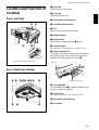
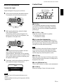
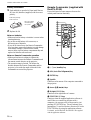
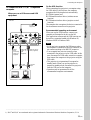
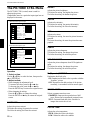
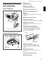
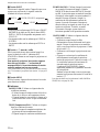
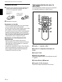
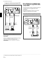
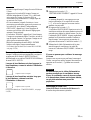
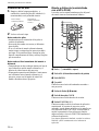
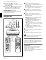
Location and Function of
Controls
Front / Left Side
1 Zoom ring
Adjusts the size of the picture.
2 Focus ring
Adjusts the picture focus.
3 Front remote control detector
4 Ventilation holes (exhaust)
5 Lens
Remove the lens cap before projection.
6 Adjuster buttons
7 Handle release
Push to make the carrying handle 0 pop up.
8 Connector panel
For details, see “Connector Panel” on page 13 (GB).
9 Connector panel cover
If necessary, open this cover to use the connectors on
the connector panel. You can remove the cover by
releasing the connector panel cover lock qf.
PUSH
q; Carrying handle
Use the handle release 7 to make the handle pop up
from the projector for carrying.
qa Control panel
For details, see “Control Panel” on page 11 (GB).
qs Rear remote control detector
qd Left speaker
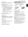
Rear / Right Side / Bottom
Location and Function of Controls
1
2
3
45
67
8
q;qa
9
P
U
S
H
PUSH
qd qs ws ql wa w; ql qk qj
qgqf qh
Left side
Connector panel cover
(This illustration shows the VPL-PX15.)

10 (GB)
qf Connector panel cover lock
Used to remove/install the connector panel cover 9.
qg Rear adjusters
qh Adjusters
When a picture is projected on an exterior of the
screen, adjust the picture using these adjusters.
For details on how to use the adjusters, see “How to use
the adjusters” on page 11 (GB).
qj Security lock
Connects to an optional security cable (made by
Kensington)
1)
.
The security lock corresponds to Kensington’s
MicroSaver
®1)
Security System.
If you require further information, contact
Kensington
2855 Campus Drive, San Mateo, CA 94403
In North America
Phone: 800-235-6708
Fax: 800-247-1317
Outside North America
Phone: 847-541-9500
Home page address:
http://www.kensington.com/
qk Lamp cover
ql Ventilation holes (intake)
w; Right speaker
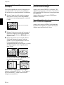
Location and Function of Controls
Bottom
While pressing both sides of the lock, slide the
connector cover outward to release it.
1
1
2
wa Air filter cover lock
Used to remove the air filter cover.
For details, see “Cleaning the Air Filter” on page 38 (GB).
Note
Clean the air filter every 300 hours to ensure
optimal performance.
ws Ventilation holes (intake) / air filter cover
Notes
•Do not place anything near the ventilation holes as it
may cause internal heat build-up.
•Do not place your hand or objects near the
ventilation holes — the air coming out is hot.
.........................................................................................................................................................................................................
1) Kensington and MicroSaver are registered trademarks of Kensington Technology Group.

11 (GB)
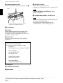
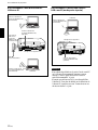
How to use the adjusters
To adjust the height
Adjust the height of the projector as follows:
1 Lift the projector and press the adjuster buttons.
The adjusters will extend from the projector.
2 While pressing the buttons, adjust the height.
Then, release the buttons.
The adjusters will lock, then the height of the
projector will be fixed. For fine adjustment, turn
the adjusters to the right or left.
Note
If the adjusters have been extended to the limit
and you keep turning the adjusters
counterclockwise, the adjusters will stop turning
and the adjuster buttons cannot be pressed. In this
case, turn the adjusters clockwise, and then press
the adjuster buttons again.
3 If necessary, turn the rear adjusters to the right or
left to adjust the height of the projector.
Notes
•Be careful not to let the projector down on your
fingers.
•Do not push hard on the top of the projector with the
adjusters out.
Adjuster buttons
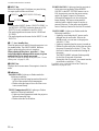
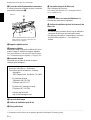
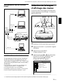
Control Panel
1 HELP key
If you need help information during an operation,
press this key to display help messages. The Help
menu lists error recovery techniques depending on
problem type.
2 VOLUME +/– keys
Adjust the volume of the built-in speakers.
+ : Increases the volume.
– : Decreases the volume.
3 APA (Auto Pixel Alignment) key
Adjusts the picture to be projected automatically to
give the clearest picture possible while a signal from
the computer is input. Adjusts the shift (up/down and
left/right) at the same time automatically.
Note
Press the APA key when the full image is displayed
on the screen. If there are black edges around the
image, the APA function will not function properly
and the image may extend beyond the screen.
4 RESET key
Resets the value of an item to its factory preset value.
This key functions when the menu or a setting item is
displayed on the screen.
5 Arrow (M/m/</,) keys
Used to select a menu or to make various adjustments.
6 ENTER key
Enters the settings of items in the menu system.
HELP
LAMP/
COVER
TEMP/
FAN
POWER
SAVING
ON/
STANDBY
RESET
APA
VOLUME
ENTER
INPUT
MENU
12345678
q;
9
Location and Function of Controls

12 (GB)
7 INPUT key
Selects the input signal. Each time you press the key,
the input signal switches as follows:
Notes
•You can select INPUT-B only if INPUT-B FUNC. in
the INSTALL SETTING menu has been set to ON.
INPUT-B is only available for the VPL-PX15.
•The audio signals are the same for the VIDEO and
S-VIDEO.
•The audio signals are the same for the INPUT-A and
INPUT-B.
8 I / 1 (on / standby) key
Turns the projector on and off when the projector is in
the standby mode. The ON/STANDBY indicator
lights in green when the power is turned on.
When turning off the power, press the I / 1 key
twice following the message on the screen, or press
and hold the key for about one second.
For details on steps for turning off the power, see “To turn
off the power” on page 25 (GB).
9 MENU key
Displays the on-screen menu. Press again to clear the
menu.
0 Indicators
LAMP/COVER: Lights up or flashes under the
following conditions:
• Lights up when the lamp has reached the end of
its life or has reached a high temperature.
• Flashes when the lamp cover or air filter cover
is not secured firmly.
TEMP (Temperature)/FAN: Lights up or flashes
under the following conditions:
• Lights up when temperature inside the projector
becomes unusually high.
• Flashes when the fan is broken.
Location and Function of Controls
INPUT-A
S-VIDEO VIDEO
INPUT-B (VPL-PX15 only)
POWER SAVING: Lights up when the projector is
in the power saving mode. When POWER
SAVING in the SET SETTING menu is set to
ON, the projector goes into the power saving
mode if no signal is input for 10 minutes.
Although the lamp goes out, the cooling fan
keeps running. The power saving mode is
canceled when a signal is input or any key is
pressed. However, in the power saving mode,
none of the keys function for the first 60 seconds.
ON/STANDBY: Lights up or flashes under the
following conditions:
• Lights up in red when the AC power cord is
plugged into the wall outlet. Once in the
standby mode, you can turn on the projector
with the
I / 1
key.
• Lights up in green when the power is turned on.
• Flashes in green while the cooling fan runs after
the power is turned off with the
I / 1
key. The
fan runs for about 90 seconds after turning off
the power.
The ON/STANDBY indicator flashes quickly
for the first 60 seconds of that time.
During this first 60 seconds, you cannot turn the
power back on with the
I / 1
key.
For details on the LAMP/COVER and the TEMP/FAN
indicators, see page 40 (GB).

13 (GB)
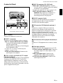
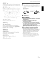
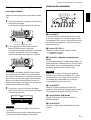
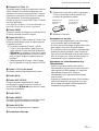
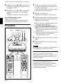
Location and Function of Controls
Connector Panel
Left side
INPUT B
PC CARD
MOUSE
CTRL S
PLUG IN POWER
AUDIO
AUDIO
VIDEO
S VIDEO
INPUT A ~AC IN
INPUT B
PC CARD
MOUSE
CTRL S
PLUG IN POWER
AUDIO
AUDIO
VIDEO
S VIDEO
INPUT A ~AC IN
56 7 8
4321
PUSH
1 AC IN socket
Connects the supplied AC power cord.
2 INPUT A connectors
Connect to external equipment such as a computer.
INPUT A connector (HD D-sub 15-pin, female):
Connects to the monitor output on a computer
using the supplied cable.
When inputting a component or 15k RGB signal,
use the appropriate cable.
For details, see “To connect 15k RGB/Component
equipment” on page 21 (GB).
AUDIO jack (stereo minijack): Connects to the
audio output of the computer.
3 CTRL S /PLUG IN POWER (DC 5V output)
jack (stereo minijack)
Connects to the control S out jack of Sony equipment.
Connects to the CONTROL S OUT jack on the
supplied Remote Commander to use it as a wired
remote control unit. In this case, you do not need to
install batteries in the Remote Commander, since the
power is supplied from this jack.
4 INPUT B connectors (VPL-PX15 only)
INPUT B PC CARD slot (Type II): A wireless
LAN PC card or PC memory card can be installed
according to your requirements.
For details, see “Installing a PC card” on page 21 (GB).
INPUT B ETHER connector (10BASE-T/
100BASE-TX): Connects to a computer on a
LAN with a LAN cable when you use the
networking function of this projector.
5 MOUSE connector (6-pin)
Connects to the PS/2 mouse port on a computer via
the supplied mouse cable, to control the mouse
function of the connected computer.
6 USB connector (USB B-plug for upstream, 4-
pin)
Connects to a computer. When you connect the
projector to the computer via this connector, the
projector recognizes that a USB mouse is connected
and you can control the mouse function of the
computer connected to the INPUT A connector using
the supplied Remote Commander. The supplied
application software can be used on the computer
connected to this connector.
7 USB connector (USB A-plug for downstream, 4-
pin)
Connects to USB equipment such as a mouse, camera,
etc.
8 Video input connectors
Connect to external video equipment such as a VCR.
S VIDEO connector (mini DIN 4-pin): Connects to
the S video output (Y/C video output) of video
equipment.
VIDEO jack (phono type): Connects to the
composite video output of video equipment.
AUDIO jack (stereo minijack): Connects to the
audio output of the VCR.
(This illustration shows the VPL-PX15.)

14 (GB)
Location and Function of Controls
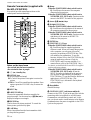
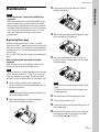
Remote Commander (supplied with
the VPL-PX15/PX10)
Keys which have the same names as those on the
control panel function identically.
Notes on the laser beam
•Do not look into the laser transmitter.
•Do not aim the laser at people.
1
I
/
1
(on / standby) key
2 MUTING keys
Cut off the picture and sound.
PIC: Cuts off the picture. Press again to restore the
picture.
AUDIO: Cuts off the sound from the speakers. Press
again or press the VOLUME + key to restore the
sound.
3 INPUT key
4 D KEYSTONE key
Corrects the trapezoidal distortion caused by the
projection angle. Use the arrow keys (M/m/</,) to
display the image as a rectangle.
5 FREEZE key
Used to freeze the picture projected. To cancel the
frozen picture, press the key again.
6 LASER key
Emits a laser beam from the laser transmitter while
you keep this key pressed.
MUTING
PIC
AUDIO
HELP
APA
LASER
INPUT
D KEYSTONE
FREEZE
PJ NETWORK
ON
COMMAND
OFF
VOLUME
ENTER
FUNCTION
RM-PJM15
PROJECTOR
D ZOOM
CLICK
RESET/
ESCAPE
MENU/
TAB
R
1
2
3
1
2
3
4
5
6
7
8
9
q;
qa
wf
wd
ws
wa
w;
ql
qk
qj
qh
qg
qf
qs,qd
wg
7 Mouse
When the PJ/NETWORK select switch is set to
PJ: Functions as the mouse of the computer
connected to this projector.
When the PJ/NETWORK select switch is set to
NETWORK (VPL-PX15 only): Functions as the
mouse in the INPUT B window of this projector.
8 Arrow (M/m/</,) keys
9 R (right) CLICK key
When the PJ/NETWORK select switch is set to
PJ: Functions as the right button of the mouse of
the computer connected to this projector.
When the PJ/NETWORK select switch is set to
NETWORK (VPL-PX15 only): Functions as the
right button of the mouse in the INPUT B
window of this projector.
0 ENTER key
qa FUNCTION 1, 2, 3 keys
When the PJ/NETWORK select switch is set to
PJ: Functions when the supplied application
software is used. When you connect the projector
with a computer, you can open a file on the
screen by just pressing a FUNCTION key. This
will enhance your presentation. To use this
function, allocate a file to the FUNCTION key by
using the application software. (Only the
FUNCTION 1 and 2 keys are available. You
cannot allocate a file to the FUNCTION 3 key.)
For details, see the README file and HELP file supplied
with the application software.
When the PJ/NETWORK select switch is set to
NETWORK (VPL-PX15 only): When the
INPUT B window is displayed on the projector,
you can start an application by just pressing a
FUNCTION key. To use this function, allocate an
application to a FUNCTION key. (The
FUNCTION 3 key is allocated to the keyboard
software display.)
qs Strap holder
Attaches the strap.
qd CONTROL S OUT jack (stereo minijack)
Connects to the CTRL S jack on the projector with the
connecting cable (not supplied) to use the Remote
Commander as a wired remote control unit. In this
case, you do not need to install batteries in the Remote
Commander since the power is supplied via the CTRL
S jack on the projector.

15 (GB)
Location and Function of Controls
qf RESET/ESCAPE key
When the PJ/NETWORK select switch is set to
PJ: Functions as the RESET key.
When the PJ/NETWORK select switch is set to
NETWORK (VPL-PX15 only): Functions as the
ESCAPE key of the keyboard when the INPUT B
window is displayed.
qg D ZOOM +/– key
Enlarges the image at a desired location on the screen.
This key works only when a signal from a computer is
input.
+: Pressing the + key once displays the icon. This
icon indicates the point you want to enlarge. Use
an arrow key (M/m/</,) to move the icon to
the point to be enlarged. Press the + key
repeatedly until the image is enlarged to meet
your requirements.
–: Each press of the – key reduces an image that has
been enlarged with the D ZOOM + key.
qh L (left) CLICK key
When the PJ/NETWORK select switch is set to
PJ: Functions as the left button of the mouse of
the computer connected to this projector.
When the PJ/NETWORK select switch is set to
NETWORK (VPL-PX15 only): Functions as the
left button of the mouse in the INPUT B window
of this projector.
qj MENU/TAB key
When the PJ/NETWORK select switch is set to
PJ: Functions as the MENU key.
When the PJ/NETWORK select switch is set to
NETWORK (VPL-PX15 only): Functions as the
TAB key of the keyboard when the INPUT B
window is displayed.
qk APA (Auto Pixel Alignment) key
ql VOLUME +/– keys
w; HELP key
If you need help information during an operation,
press this key to display help messages.
wa PJ/NETWORK select switch
To use the Remote Commander for network
operations, set the switch to NETWORK. Set the
switch to PJ to use the Remote Commander for
normal operations other than networking. This switch
is only available for the VPL-PX15.
For details on the operation of the Windows CE screen, see
the supplied “Operating Instructions for Networking.”
ws COMMAND ON/OFF switch
When this switch is set to OFF, no keys on the
Remote Commander will function. This saves battery
power.
wd Transmission indicator
Lights up when you press a key on the Remote
Commander.
This indicator does not light up when you use the laser
pointer.
wf Infrared transmitter
wg Laser transmitter

16 (GB)
Location and Function of Controls
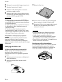
Battery installation
1 Push and slide to open the lid, then install the two
R6 (size AA) batteries (supplied) with the correct
polarity.
2 Replace the lid.
Notes on batteries
•Make sure that the battery orientation is correct when
inserting batteries.
•Do not mix an old battery with a new one, or
different types of batteries.
•If you do not intend to use the Remote Commander
for a long time, remove the batteries to avoid damage
from battery leakage. If batteries have leaked,
remove them, wipe the battery compartment dry and
replace the batteries with new ones.
Notes on Remote Commander operation
•Make sure that there is nothing to obstruct the
infrared beam between the Remote Commander and
the remote control detector on the projector.
•The operation range is limited. The shorter the
distance between the Remote Commander and the
projector is, the wider the angle within which the
commander can control the projector.
Be sure to install
the battery from
the # side.
Slide while pressing
down on the lid.
Remote Commander (supplied with
the VPL-PS10)
Keys which have the same names as those on the
control panel function identically.
1
I
/
1
(on / standby) key
2 APA (Auto Pixel Alignment) key
3 ENTER key
4 Joystick
Functions as the mouse of the computer connected to
this projector.
5 Arrow (M/m/</,) keys
6 R (right) CLICK key
Functions as the right button of a mouse.
7 FUNCTION 1, 2 keys
Functions when the supplied application software is
used. When you connect the projector with a
computer, you can open a file on the screen by just
pressing a FUNCTION key. This will enhance your
presentation. To use this function, allocate a file to the
FUNCTION key by using the application software.
For details, see the README file and HELP file supplied
with the application software.
I / 1
INPUT
FREEZE
MENU ENTER
D KEYSTONE
MS SLIDE
RESET
FUNCTION
D ZOOM
12
APA
+
–
R
CLICK
1
2
3
4
5
6
7
8
9
q;
qa
qs
qd
qf
qg
qh

17 (GB)
8 RESET key
Resets the value of an item to its factory preset value
or returns the enlarged image back to its original size.
9 D ZOOM +/– key
Enlarges the image at a desired location on the screen.
This key works only when a signal from a computer is
input.
+: Pressing the + key once displays the icon. This
icon indicates the point you want to enlarge. Use
an arrow key (M/m/</,) to move the icon to
the point to be enlarged. Press the + key
repeatedly until the image is enlarged to meet
your requirements.
–: Each press of the – key reduces an image that has
been enlarged with the D ZOOM + key.
0 L (left) CLICK key
Functions as the left button of a mouse.
qa MENU key
qs D KEYSTONE key
Corrects the trapezoidal distortion caused by the
projection angle. Use the arrow keys (M/m/</,) to
display the image as a rectangle.
qd INPUT key
qf FREEZE key
Used to freeze the picture projected. To cancel the
frozen picture, press the key again.
qg MS SLIDE key
This key does not operate with this unit.
qh Infrared transmitter
Battery installation
1 Push and slide to open the lid, then install the two
R6 (size AA) batteries (supplied) with the correct
polarity.
2 Replace the lid.
Notes on batteries
•Make sure that the battery orientation is correct when
inserting batteries.
•Do not mix an old battery with a new one, or
different types of batteries.
•If you do not intend to use the Remote Commander
for a long time, remove the batteries to avoid damage
from battery leakage. If batteries have leaked,
remove them, wipe the battery compartment dry and
replace the batteries with new ones.
Notes on Remote Commander operation
•Make sure that there is nothing to obstruct the
infrared beam between the Remote Commander and
the remote control detector on the projector. Direct
the Remote Commander toward the front or rear
remote control detector.
•The operation range is limited. The shorter the
distance between the Remote Commander and the
projector is, the wider the angle within which the
commander can control the projector.
Be sure to install
the battery from
the # side.
Slide while pressing
down on the lid.
Location and Function of Controls

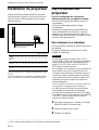
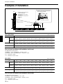
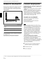
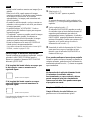
18 (GB)
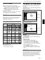
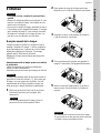
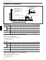
Installing the Projector / Connecting the Projector
Installing the Projector
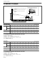
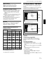
This section describes how to install the projector.
The distance between the lens and the screen varies
depending on the size of the screen. Use the following
table as a guide.
For details, see “Installation Example” on page 34 (GB).
For details on ceiling installation, consult with qualified
Sony personnel (fee charged).
Distance between the screen
and the center of the lens
Unit: m (feet)
Screen
size 40 60 80 100 120 150 180 200 250 300
(inches)
Minimum 1.5 2.2 3.0 3.7 4.5 5.6 6.8 7.5 9.4 11.3
Distance (4.8) (7.3) (9.8) (12.3) (14.8)(18.5) (22.3)(24.8) (31.0)(37.3)
Maximum 1.8 2.7 3.6 4.5 5.4 6.8 8.1 9.1 11.3 13.6
Distance (5.8) (8.8) (11.8) (14.8) (17.8)(22.2) (26.7)(29.7) (37.2) (44.7)
PUSH
Connecting the Projector
When making connections, be sure to do the
following:
•Turn off all equipment before making any
connections.
•Use the proper cables for each connection.
•Insert the cable plugs properly; plugs that are not
fully inserted often generate noise or cause picture
degradation. When pulling out a cable, be sure to
pull it out grasping the plug, not the cable itself.
Connecting to a Computer
This section describes how to connect the projector to
a computer.
For more information, refer to the computer’s
instruction manual.
Notes
•The projector accepts VGA, SVGA, XGA, and
SXGA signals. However, we recommend that you
set the output mode of your computer to SVGA
(VPL-PS10) or XGA (VPL-PX15/PX10) mode for
the external monitor.
•If you set your computer, such as a notebook type, to
output the signal to both your computer’s display and
an external monitor, the picture of the external
monitor may not appear properly. Set your computer
to output the signal to only the external monitor.
For details, refer to the operating instructions supplied
with your computer.
•The supplied mouse cable may not work properly
depending on your computer.
•This projector is compatible with DDC2B (Display
Data Channel 2B). If your computer is compatible
with DDC
1)
, turn the projector on according to the
following procedures.
1 Connect the projector to the computer using the
supplied HD D-sub 15-pin cable.
2 Turn the projector on.
3 Start the computer.
.........................................................................................................................................................................................................
1) DDC™ is a registered trademark of the Video Electronics Standards Association.

19 (GB)
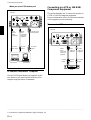
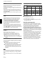
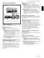
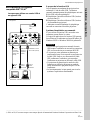
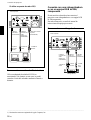
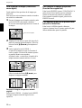
Connecting the Projector
Setting Up and Projecting
On the USB function
When connecting the projector to a computer using
the USB cable for the first time, the computer
recognizes the following devices automatically.
1 USB hub (general use)
2 USB human interface device (wireless mouse
function)
3 USB human interface device (projector control
function)
The computer also recognizes the device connected to
the downstream connector on the projector.
Recommended operating environment
When you use the USB function, connect your
computer as illustrated in the box on the left.
This application software and the USB function can
be used on a computer loaded with Windows 98,
Windows 98 SE or Windows 2000.
Notes
• As the projector recognizes the USB mouse when
the computer is connected to the USB connector, do
not connect anything to the MOUSE connector.
• Your computer may not start correctly when
connected to the projector via the USB cable. In this
case, disconnect the USB cable, restart the computer,
then connect the computer to the projector using the
USB cable.
• This projector is not guaranteed for suspend or
standby mode. When you use the projector in
suspend or standby mode, disconnect the projector
from the USB port on the computer.
• Operations are not guaranteed for all the
recommended computer environments.
To connect an IBM
1)
PC/AT
1)
compatible
computer
When you use a USB mouse and USB
equipment
MOUSE
CTRL S
PLUG IN POWER
AUDIO
AUDIO
VIDEO
S VIDEO
INPUT A ~AC IN
USB cable
A type – B
type
(supplied)
Left side
HD D-sub 15-pin
cable (supplied)
Stereo
audio
connecting
cable (not
supplied)
to monitor
output
to audio
output
to USB
equipment
to USB
connector
.........................................................................................................................................................................................................
1) IBM
®
and PC/AT are a trademark and a registered trademark of International Business Machines Corporation, U.S.A.
Computer

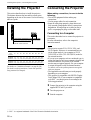
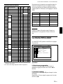
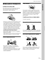
20 (GB)
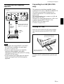
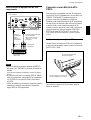
Connecting to a VCR or 15k RGB/
Component Equipment
This section describes how to connect the projector to
a VCR or 15k RGB/component equipment.
For more information, refer to the instruction manuals
of the equipment you are connecting.
To connect a VCR
MOUSE
CTRL S
PLUG IN POWER
AUDIO
AUDIO
VIDEO
S VIDEO
INPUT A ~AC IN
S-Video
cable (not
supplied)
Left side
to audio
output
Video
cable (not
supplied)
VCR
to S video
output
to video
output
.........................................................................................................................................................................................................
1) Macintosh is a registered trademark of Apple Computer, Inc.
Connecting the Projector
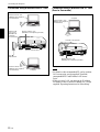
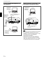
When you use a PS/2 mouse port
MOUSE
CTRL S
PLUG IN POWER
AUDIO
AUDIO
VIDEO
S VIDEO
INPUT A ~AC IN
Stereo
audio
connecting
cable (not
supplied)
Left side
HD D-sub 15-pin
cable (supplied)
PS/2
Mouse
cable
(supplied)
to monitor
output
to mouse
port (PS/2)
to audio
output
To connect a Macintosh
1)
computer
Use an ADP-20 signal adapter (not supplied). In this
case, however, you cannot control the mouse of the
computer using the Remote Commander.
Computer
Stereo
audio
connecting
cable (not
supplied)

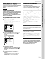
21 (GB)
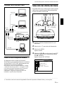
To connect 15k RGB/Component
equipment
Notes
• Set the aspect ratio using ASPECT in the INPUT
SETTING menu according to the input signal.
For details, see page 30 (GB).
• When you connect the projector to 15k RGB/
component video equipment, select RGB,
component or VCR GBR with the INPUT-A setting
in the SET SETTING menu.
• Use the composite sync signal when you input the
external sync signal from 15k RGB/component
equipment.
MOUSE
CTRL S
PLUG IN POWER
AUDIO
AUDIO
VIDEO
S VIDEO
INPUT A ~AC IN
SMF-402 Signal Cable (not
supplied) HD D-sub 15-pin
(male) y 3 × phono jack
Left side
to audio
output
Stereo
audio
connecting
cable (not
supplied)
15k RGB/Component
equipment
to RGB/
component
output
PUSH
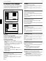
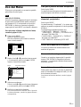
Connecting to a LAN (VPL-PX15
only)
This projector is networking compatible. Using a
wireless LAN PC card or a 10BASE-T/100BASE-TX
LAN cable, you can connect the projector to a
wireless or wired LAN. You can also install a PC
memory card.
This section describes how to connect to a LAN and
how to install a PC card.
Whenever you connect the projector to a LAN or use
a memory card, set INPUT-B FUNC. in the
INSTALL SETTING menu to ON.
For details, see page 33 (GB).
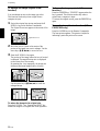
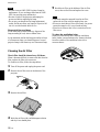
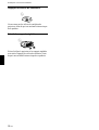
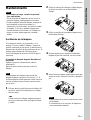
Installing a PC card
When you use a wireless LAN PC card or memory
card, insert the card into the INPUT B PC CARD
slot.
To remove the PC card from the slot, press the eject
button.
PC card
Insert the card with the arrow mark
facing toward the slot.
The eject button pops out
when the card is inserted.
Connecting the Projector
Page is loading ...
Page is loading ...
Page is loading ...
Page is loading ...
Page is loading ...
Page is loading ...
Page is loading ...
Page is loading ...
Page is loading ...
Page is loading ...
Page is loading ...
Page is loading ...
Page is loading ...
Page is loading ...
Page is loading ...
Page is loading ...
Page is loading ...
Page is loading ...
Page is loading ...
Page is loading ...
Page is loading ...
Page is loading ...
Page is loading ...
Page is loading ...
Page is loading ...
Page is loading ...
Page is loading ...
Page is loading ...
Page is loading ...
Page is loading ...
Page is loading ...
Page is loading ...
Page is loading ...
Page is loading ...
Page is loading ...
Page is loading ...
Page is loading ...
Page is loading ...
Page is loading ...
Page is loading ...
Page is loading ...
Page is loading ...
Page is loading ...
Page is loading ...
Page is loading ...
Page is loading ...
Page is loading ...
Page is loading ...
Page is loading ...
Page is loading ...
Page is loading ...
Page is loading ...
Page is loading ...
Page is loading ...
Page is loading ...
Page is loading ...
Page is loading ...
Page is loading ...
Page is loading ...
Page is loading ...
Page is loading ...
Page is loading ...
Page is loading ...
Page is loading ...
Page is loading ...
Page is loading ...
Page is loading ...
Page is loading ...
Page is loading ...
Page is loading ...
Page is loading ...
Page is loading ...
Page is loading ...
Page is loading ...
Page is loading ...
Page is loading ...
Page is loading ...
Page is loading ...
Page is loading ...
Page is loading ...
Page is loading ...
Page is loading ...
Page is loading ...
Page is loading ...
Page is loading ...
Page is loading ...
Page is loading ...
Page is loading ...
Page is loading ...
Page is loading ...
Page is loading ...
Page is loading ...
Page is loading ...
Page is loading ...
Page is loading ...
Page is loading ...
Page is loading ...
Page is loading ...
Page is loading ...
Page is loading ...
Page is loading ...
Page is loading ...
Page is loading ...
Page is loading ...
Page is loading ...
Page is loading ...
Page is loading ...
-
 1
1
-
 2
2
-
 3
3
-
 4
4
-
 5
5
-
 6
6
-
 7
7
-
 8
8
-
 9
9
-
 10
10
-
 11
11
-
 12
12
-
 13
13
-
 14
14
-
 15
15
-
 16
16
-
 17
17
-
 18
18
-
 19
19
-
 20
20
-
 21
21
-
 22
22
-
 23
23
-
 24
24
-
 25
25
-
 26
26
-
 27
27
-
 28
28
-
 29
29
-
 30
30
-
 31
31
-
 32
32
-
 33
33
-
 34
34
-
 35
35
-
 36
36
-
 37
37
-
 38
38
-
 39
39
-
 40
40
-
 41
41
-
 42
42
-
 43
43
-
 44
44
-
 45
45
-
 46
46
-
 47
47
-
 48
48
-
 49
49
-
 50
50
-
 51
51
-
 52
52
-
 53
53
-
 54
54
-
 55
55
-
 56
56
-
 57
57
-
 58
58
-
 59
59
-
 60
60
-
 61
61
-
 62
62
-
 63
63
-
 64
64
-
 65
65
-
 66
66
-
 67
67
-
 68
68
-
 69
69
-
 70
70
-
 71
71
-
 72
72
-
 73
73
-
 74
74
-
 75
75
-
 76
76
-
 77
77
-
 78
78
-
 79
79
-
 80
80
-
 81
81
-
 82
82
-
 83
83
-
 84
84
-
 85
85
-
 86
86
-
 87
87
-
 88
88
-
 89
89
-
 90
90
-
 91
91
-
 92
92
-
 93
93
-
 94
94
-
 95
95
-
 96
96
-
 97
97
-
 98
98
-
 99
99
-
 100
100
-
 101
101
-
 102
102
-
 103
103
-
 104
104
-
 105
105
-
 106
106
-
 107
107
-
 108
108
-
 109
109
-
 110
110
-
 111
111
-
 112
112
-
 113
113
-
 114
114
-
 115
115
-
 116
116
-
 117
117
-
 118
118
-
 119
119
-
 120
120
-
 121
121
-
 122
122
-
 123
123
-
 124
124
-
 125
125
-
 126
126
-
 127
127
-
 128
128


Sony Sony VPL-PS10 User manual
- Category
- Data projectors
- Type
- User manual
Ask a question and I''ll find the answer in the document
Finding information in a document is now easier with AI
in other languages
- français: Sony Sony VPL-PS10 Manuel utilisateur
- español: Sony Sony VPL-PS10 Manual de usuario

