Danfoss 187F9011 User guide

Type
User guide
www.danfoss.com
Installation Guide
Infocal 9
Energy calculator
for heating and cooling applications
2 | © Danfoss | Energy Meters | 2020.01 BC266538737985en-000103
Installation Guide Infocal 9
BC266538737985en-000103 © Danfoss | Energy Meters | 2020.01 | 3
Installation Guide Infocal 9
1. Installation
1.1. Preparation
Only qualified personnel may install the equipment, following the requirements listed in this document.
More detailed instructions can be found on www.heating.danfoss.com.
1.2. Identification of installation: Return or Supply pipe flow meter/sensor installation
Flow direction
Flow meter/sensor installed in return pipe
Flow direction
Flow meter/sensor installed in supply pipe
4 | © Danfoss | Energy Meters | 2020.01 BC266538737985en-000103
Installation Guide Infocal 9
1.3. Installation of temperature sensors
Handle the temperature sensors carefully! The sensor cables are fitted with coloured type labels:
• Red (TH): sensor in supply pipe
• Blue (TC): sensor in return pipe
Make sure the sensors are mounted symmetrically (both directly immersed, or both installed in a pocket).
The maximum cable length is 10 m. The connecting cables must not be shortened or extended. The free
temperature sensors can be installed in a ball valve or adapter or in a conformity tested pocket for this type
of sensor. Ensure that the temperature sensors are permanently connected during operation.
For installation in a ball valve or adapter, a 4-piece coupling set is enclosed in a separate bag. See procedure
under item 1…5 on the right. Insert an O-ring in the sensor hole using the mounting pin supplied.
If the sensor is installed in a pocket, it must be inserted as far as the bottom of the pocket and then secured.
The pockets are best installed in T-pieces with a 45° or 90° angle. The tip of the pocket must point in the op-
posite direction to the direction of flow and must be located in the middle of the pipe. Temperature sensors
must be sealed after installation in the pockets.
The operation of any violation of this guidance will result in immediate invalidation of the factory
warranty and verification.
Seal
Pocket
a) angled 45°
Seal
P
ocket
b) perpendicular
Installation recommendations for pocket temperature sensors with permanently connected signal leads.
Temperature sensor cables should be connected to terminals as shown in below table:
Calculator type Sensor marking
Wiring 2-wire
sensor
Wiring 4-wire
sensor
Installation
position
Heating or
Heating/cooling
Red T
Hot
(5-6) T
Hot
(1/5-6/2) Supply pipe
Blue T
Cold
(7-8) T
Cold
(3/7-8/4) Return pipe
1.4. Mounting and sealing of calculator
On the wall:
On standard DIN-rail:
BC266538737985en-000103 © Danfoss | Energy Meters | 2020.01 | 5
Installation Guide Infocal 9
1.5. Flow meter or flow sensor connection
For connection of flow meter/sensor to energy calculator Infocal 9 it is important to know in which pipe
(supply –q1 or return – q2) this flow meter/sensor will be installed:
Flow sensor in return pipe
Infocal 9 terminal
External 3.6 V* 9(+U)
Flow pulse 52 (q2+)
Ground 11 (q2-)
Wiring to flow meter SONO 3500 CT:
SONO 3500 CT in
supply pipe
Infocal 9 terminal
56 (flow pulse) 10 (q1+)
57 (ground) 11 (q1-)
SONO 3500 CT in
return pipe
Infocal 9 terminal
56 (flow pulse) 52 (q2+)
57 (ground) 11 (q2-)
Wiring to flow sensor SonoSensor 30:
SonoSensor 30 in
supply pipe
Infocal 9 terminal
18 (flow pulse) 10 (q1+)
19 (ground) 11 (q1-)
SonoSensor 30 in
return pipe
Infocal 9 terminal
18 (flow pulse) 52 (q2+)
19 (ground) 11 (q2-)
Wiring to flow sensor SONO 1500 CT:
SONO 1500 CT in
return pipe
Infocal 9 terminal
Vcc (brown)* 9 (+U)
Pulse (white) 52 (q2+)
GND (blue) 11 (q1-)
Flow sensor in supply pipe
Infocal 9 terminal
External 3.6 V* 9(+U)
Flow pulse 10 (q1+)
Ground 11 (q1-)
*only if external supply for flow meter/sensor is needed.
white
blue
yello
w
brown
6 | © Danfoss | Energy Meters | 2020.01 BC266538737985en-000103
Installation Guide Infocal 9
SONO 1500 CT in
supply pipe
Infocal 9 terminal
Vcc (brown)* 9 (+U)
Pulse (white) 10 (q1+)
GND (blue) 11 (q1-)
*connect only if SONO 1500 CT with external supply.
Maximum permissible pulse input frequency and minimal permissible pulse and pause duration, depending
on pulse type and cable length:
Power supply type for calculator,
flow pulse input type
Sensor cable
length [m]
Maximum per-
missible pulse
frequency [Hz]
Minimal permissible
pulse and pause
duration [ms]
Mains supply or active pulses ≤ 100 200 2.5
Battery supply and passive pulses
≤ 10 200 2.5
≤ 50 10 50
2. Electrical wiring
Electrical wiring diagram with 2-wire temperature sensors
q1 - pulse input signal from flow meter in supply pipe
q2 - pulse input signal from flow meter in return pipe
q3, q4 - pulse inputs from water meters
T1 - temperature sensor in supply pipe
T2 - temperature sensor in return pipe
Note: Only required for selected calculator type should be connected
BC266538737985en-000103 © Danfoss | Energy Meters | 2020.01 | 7
Installation Guide Infocal 9
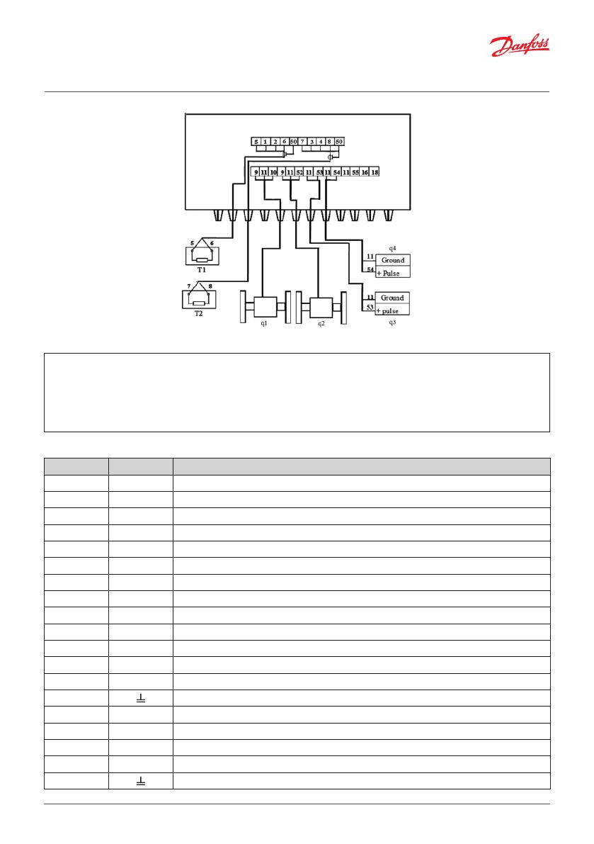
Electrical wiring diagram with 4-wire temperature sensors
Calculator
Terminal Marking Description
9 +U +3,6V power supply (only if mains supply)
11 -q1 Ground for 1-st flow sensor (-)
10 +q1 Pulse input signal from flow meter in supply pipe
11 -q2 Ground for flow sensor
52 +q2 Pulse input signal from flow meter in return pipe
11 -q3 Ground for 3-rd flow sensor (-)
53 +q3 Pulse input signal from 3-rd flow sensor (+)
11 -q4 Ground for 4-th flow sensor (-)
54 +q4 Pulse input signal from 4-th flow sensor (+)
5 T1 Current terminal for 1-st temperature sensor “+I”
1 T1 Voltage terminal for 1-st temperature sensor “+U”
2 T1 Voltage terminal for 1-st temperature sensor “-U”
6 T1 Current terminal for 1-st temperature sensor “-I”
50 Shield terminal (for 1-st temperature sensor etc.)
7 T2 Current terminal for 2-nd temperature sensor “+I”
3 T2 Voltage terminal for 2-nd temperature sensor “+U”
4 T2 Voltage terminal for 2-nd temperature sensor “-U”
8 T2 Current terminal for 2-nd temperature sensor “-I”
50 Shield terminal (for 2-nd temperature sensor etc. )
q1 - pulse input signal from flow meter in supply pipe
q2 - pulse input signal from flow meter in return pipe
q3, q4 - pulse inputs from water meters
T1 - temperature sensor in supply pipe
T2 - temperature sensor in return pipe
Note: Only required for selected calculator type should be connected
8 | © Danfoss | Energy Meters | 2020.01 BC266538737985en-000103
Installation Guide Infocal 9
Communication modules
Terminal Marking Description
76 Current output ground (-)
77 Iout1 1-st current output (+)
78 Iout2 2-st current output (+)
79 Pulse output ground (-)
80 Puls1 1-st pulse output (+)
81 Puls2 2-st pulse output (+)
24, (73) BUS M-Bus interface L1 signal (M-Bus , CL – -CL or RS232 – Rx (input))
25, (74) BUS M-Bus interface L2 signal (M-Bus , CL – +CL or RS232 – Tx (output))
75 BUS Ground for RS-232 interface “GND”
Power supply
To ensure constant pulse read out, recommended is connecting ground terminal 26 of 230V AC module with
terminal 11 of Infocal 9. Infocal 9 with battery is not affected.
Terminal Marking Description
26 Main ground
27 0 Neutral
28 L Mains power supply (230V AC)
3. Commissioning
3.1. Bleeding
1. Bleed the system until the flow rate display is steady.
2. Make sure no error codes are displayed.
3. Check the display for a plausible indication of flow rate and temperatures.
BC266538737985en-000103 © Danfoss | Energy Meters | 2020.01 | 9
Installation Guide Infocal 9
4. Display function overview
4.1. Display symbols description
Parameter and group numbers Operation mode
Measurement units
Group of parameters
V
alues
L1 L2 L3 L4 L5
4.2. Menu structure
Parameters shown Identification symbols
Integral values
L1
L2 L3 L4 L5
Instantaneous parameters values (L2) L1
L2
L3 L4 L5
Set day parameters and archive data values (L3) L1 L2
L3
L4 L5
Printing reports by standard printer (L4) L1 L2 L3
L4
L5
Configuration settings parameters (L5) L1 L2 L3 L4
L5
Parametrization (configuration) mode (SET) L1 L2
TEST
L3
L4 L5
Test mode (TEST) L1 L2
TEST
L3
L4 L5
Note: More detailed display description is available for download from www.danfoss.com.
10 | © Danfoss | Energy Meters | 2020.01 BC266538737985en-000103
Installation Guide Infocal 9
4.3. Error codes check
The calculator continuously analyzes operational modes, diagnoses and informs of errors in system.
General errors:
1-st heang system operaon error
2-nd heang system operaon error
Calculator error
Error display Error description
ErΣ: 0 No error. Normal mode.
ErΣ: 1 Warning! Estimated battery lifetime less than 6 months.
ErΣ: 5
Flow rate outside designated limits or temperature difference is under programmed
minimum allowed value (only when energy calculation algorithm “2 – special is applied).
ErΣ: 8 Flow or temperature sensor error.
Status of flow sensors:
Status of flow sensor q1
Status of flow sensor q2
Display Description
Er1: 0 No error. Normal mode.
Er1: 2 Flow rate is under programmed minimum allowed value
Er1: 4 Flow rate exceeds programmed maximum allowed value.
Er1: 8 Sensor failure (broken connection or disconnected power supply.
Status of flow
temperature sensors:
Status of sensor Θ1
Status of sensor Θ2
Display Description
Er2: 0 No error. Normal mode.
Er2: 1 Temperature difference is under programmed minimum allowed value.
Er2: 8 Sensor failure (open circuit or short circuit).
BC266538737985en-000103 © Danfoss | Energy Meters | 2020.01 | 11
Installation Guide Infocal 9
5. Disposal
This symbol on the product indicates that it will not be treated as household waste.
It must be handed over to the applicable take-back scheme for the recycling of elec-
trical and electronic equipment. For more detailed information about the recycling
of this product, please contact your local municipal office.
Item Material Disposal
Battery
D-cell lithium/thionyl chloride
3.5 g lithium
Approved deposit for lithium
batteries
PCBA with display
Coppered epoxy laminate components
soldered on, PC, TPE
Electronic waste
Other plastic parts PC, PPS, PEI, TPE Plastic recovery
12 | © Danfoss | Energy Meters | 2020.01 BC266538737985en-000103
  • Page 1 1
  • Page 2 2
  • Page 3 3
  • Page 4 4
  • Page 5 5
  • Page 6 6
  • Page 7 7
  • Page 8 8
  • Page 9 9
  • Page 10 10
  • Page 11 11
  • Page 12 12

Danfoss 187F9011 User guide

Type
User guide

Ask a question and I''ll find the answer in the document

Finding information in a document is now easier with AI