
DOC: BOS0481
D412 / D412+MC1 USER MANUAL
1 / 93
ENGLISH
D412 / D412W / +MC1
Roller Brake Tester
Garage Equipment Association
Boston Garage Equipment, 199 New Road, Rainham, Essex, RM13 8SJ, United Kingdom
T: +44 (0)1708 525585 F: +44 (0)1708 525408 info@boston-ge.com www.boston-ge.com
USER MANUAL

DOC: BOS0481
D412 / D412+MC1 USER MANUAL
2 / 93
ENGLISH
Copyright
Copyright © 2014 Boston Garage Equipment - All rights reserved worldwide.
All information contained in this document and any drawings, pictures, images and technical descriptions
which have been made available by Boston, remain the property of the company and may not, without
written permission from the company be used (except for the operation of equipment), duplicated in any
way or made available to third parties.
Disclaimer
Although every care has been taken during the preparation of this document, neither Boston or any other
company involved in its production and / or equipment production shall be liable for any damages derived
from the use of this documentation. Boston reserves the right to modify or improve its products and
literature at any time without prior notification. Any or all pictures and images in this document are for
demonstration purposes only.
This document may contain references to, or information about Boston products or services that are not yet
available. These references or information in no way mean that Boston intends to make such products
available.
This document may neither be partly or wholly duplicated, or distributed without prior authorisation from
Boston. Requests for further copies of this document or further information should be addressed to an
authorised agent, a Boston sales representative or to its e-mail address: info@boston-ge.com.
Technical and sales documentation is available on our Internet website: http://www.boston-ge.com.
Boston may have patents or applications for patents in progress involving the matters described in this
document. Supply of this document does not imply that any license to these has been granted.
Contact Details
Boston Garage Equipment
199 New Road
Rainham
Essex
RM13 8SJ
United Kingdom
Tel: +44 (0)1708 525585 Email: info@boston-ge.com
Fax: +44 (0)1708 525408 Web: www.boston-ge.com

DOC: BOS0481
D412 / D412+MC1 USER MANUAL
3 / 93
ENGLISH
Chapter 1 Introduction 5
Audience 5
Scope 5
Organisation 6
Layout Conventions 6
Related Documents 7
Chapter 2 Safety 8
General Safety Instructions 8
Maintenance Safety 9
Safety Features 9
Misuse 9
Chapter 3 Product Description 10
System Overview 10
D412B Roller Bed 12
MCU-090 (Master Control Unit) 14
GCP (Global Control Platform) 16
RFC-95 (RF Remote Control) 17
MC1 (Motorcycle Testing Cover Plate) 19
Chapter 4 General Operation 20
Power On (MCU-090) 20
Power On (BPC-091) 21
Menu Navigation 21
Mouse Control 22
Keyboard Control 23
Software Version 24
Chapter 5 Standard Brake Test 25
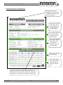
Vehicle Data Entry
26
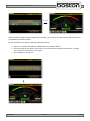
Display Layout 29
Placing Vehicle in Rollers 31
Vehicle Weight 32
Testing Front Axle 33
Testing for Imbalance 35
Testing Rear Axle 37
Contents

DOC: BOS0481
D412 / D412+MC1 USER MANUAL
4 / 93
ENGLISH
Testing the Parking Brake 37
Test Results and Printing 38
Testing 3 Wheeled Vehicles (3WV) 41
Testing Four Wheel Drive Vehicles (4WD) 42
Testing Motorcycles 45
Automated Brake Test 58
Saving Test Results 67
Chapter 6 Official Brake Tests 69
Official Tests - Data Entry 70
Manual Tests – 2WD Vehicles 74
Testing 3 Wheeled Vehicles (3WV) 79
Testing Four Wheel Drive Vehicles (4WD) 79
Testing Motorcycles 79
Official Automated Brake Test (ATL) 80
Chapter 7 DVSA Regulations UK 82
Brake Efficiency 82
Brake Imbalance 82
Efficiency Limits 83
Motorcycle Limits 84
Chapter 8 Troubleshooting and Maintenance 85
Chapter 9 Warranty / Guarantee 87
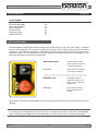
Chapter 10 Product Specifications 88
D412B Roller Bed Specification 88
RF-90 RF Remote Control Specification 89
BPC-091 Mini PC Specification 90
MCU-090 Control Unit Specification 91
CE Declaration 92
Contents

DOC: BOS0481
D412 / D412+MC1 USER MANUAL
5 / 93
ENGLISH
In This Chapter
Audience 5
Scope 5
Organisation 6
Layout conventions 6
Related documents 7
This manual is intended for the final users of the equipment who will operate and maintain the system
throughout its working life.
Boston Garage Equipment requires that operators of this equipment:
Have sufficient technical knowledge and experience to operate the equipment
Can recognize and prevent potential hazards
Have read and understood this manual
Have been adequately trained
Follow the procedure in this manual
The purpose of this manual is to:
Describe the operation of the system
Describe its operating principles and general construction
Explain safety features and safety precautions
Highlight possible hazards
Describe the operation procedures
Describe the maintenance procedures
Troubleshooting
Audience
Scope
Introduction
Chapter 1

DOC: BOS0481
D412 / D412+MC1 USER MANUAL
6 / 93
ENGLISH
This manual is organised into:
Safety – Describes safety features of the system and safety precautions to follow when operating
the system. Read this section before operation and maintenance.
Functional Description – Contains a functional description of the system.
Operating Instructions – Contains all the procedures necessary to operate the equipment safely.
Troubleshooting and Maintenance – Contains procedures to solve problems encountered during
operation and maintenance procedures that can be carried by the user.
Parts List – Contains parts lists and drawings.
In this manual we use a number of typographical conventions to highlight particularly important
information and to guide the user through the manual. This section lists these conventions.
Two types of list are used.-
1) Lists that are numbered (like this sentence) contain actions you must carry out in sequence.
In lists that use arrow points (like this sentence), the sequence is not critical.
NOTE
Text with additional information, such as expanded explanations, hints or reminders.
CAUTION
Indicates situations that can be dangerous or cause damage.
Commands (such as menu items and buttons) are bold. Menu names are also bold.
Example: On the remote control press 4.
Information that requires special attention is shown in italic.
Example: Use the Emergency Stop button only in emergencies.
Organisation
Layout Conventions

DOC: BOS0481
D412 / D412+MC1 USER MANUAL
7 / 93
ENGLISH
Document Name Document Number
SW900 User Manual BOS0320
RFC-95 User Manual BOS0423
Related Documents

DOC: BOS0481
D412 / D412+MC1 USER MANUAL
8 / 93
ENGLISH
In This Chapter
General Safety Instructions 8
Maintenance Safety 9
Safety Features 9
Misuse 9
In order to comply with your responsibilities under the Health and Safety at Work Act 1974, it is essential
that this Roller Brake Tester (RBT) and any optional accessories are sited, installed, operated, and
maintained by Boston Garage Equipment or your local authorised / approved distributor.
All persons installing, operating or maintaining the equipment and any optional accessories must be
familiar with the layout of the equipment, the safety precautions, the emergency shutdown
procedures and vehicle braking systems.
Appropriate training is required, prior to installing, using or maintaining the equipment.
The instructions in this manual must be strictly adhered to, to avoid injuries to personnel and
damage to the machine and vehicle.
Only a qualified technician should carry out work on the electrical system, and should follow
procedures pre-described by national standards.
Never remove or bypass any of the safety features.
Avoid any direct or indirect electrical contact.
The unit should be placed inside a rigid, flat and clean surface, protected against water, humidity
and weather influences.
Keep the operating environment clean and free of oil. Never leave loose objects around the RBT.
Never leave parked vehicles on the RBT overnight.
Make sure the remote control is stored safely when not in use.
The equipment may be operated only within its rated capacity. The equipment is designed for MOT
Class 1, 2, 3 & 4 vehicles.
The equipment should only be used when the operator has a good view of the whole machine.
During the test no person should stand close to the roller bed(s).
The testing area should be clear of personnel, tools and equipment before starting each stage of
the test.
Do not stand on, or walk over the rollers at any time.
Take precautions to extract exhaust in the workplace properly while testing.
Do not test a vehicle when there is insufficient light.
Never make any adjustments to the vehicle braking system when the vehicle is in the rollers.
When the RBT rollers are in operation, any key on the remote control or PC keyboard will
immediately stop the rollers, irrespective of their prescribed function.
In case of an emergency, all operations can be stopped immediately by pressing the emergency
stop button on the side of the control cabinet.
If the RBT is not working correctly, switch off immediately and refer to the user manual or contact
Boston or their local agent.
Always isolate the RBT from the power supply before maintenance.
Follow the maintenance specifications accurately.
Safety
Chapter 2
General Safety Instructions

DOC: BOS0481
D412 / D412+MC1 USER MANUAL
9 / 93
ENGLISH
In addition to the general safety instructions, the following instructions apply when carrying out
maintenance on the equipment:
Switch off the main electrical supply before opening any part of the equipment.
The equipment must only be operated within its rated capacity.
Protect the electrical parts of the equipment from water and humidity.
Only qualified technicians are permitted to do work on the electrical system of the equipment and
must follow procedures prescribed by national standards.
Many safety features are bypassed inside the service areas of the software. Only qualified service
personnel are permitted to use the service section of the software.
Any unauthorised modification or changes to the system will invalidate the CE-declaration and
equipment warranty.
The D412 RBT offers the following standard safety features to minimise personal risk as much as possible.
The RBT is provided with an emergency stop button on the side of the control cabinet by which any
active operation can be stopped immediately in case of an emergency. To release the emergency
stop button after operation, rotate the button.
The rollers of the RBT’s can only be started if the centre rotating measuring rollers are pressed
down, i.e. when there is a vehicle axle in the roller brake tester (except when 3-wheel or
motorcycle modes are selected).
By applying brake force and locking any wheels under test, the rollers will stop immediately.
Closed covers for the chain and electrical components are fitted as standard.
All electrical cabling is covered to reduce any direct danger or risk.
The RBT is ground wired to earth.
Cover plates are provided to cover the rollers when the brake tester is not in use.
Whenever the rollers of the RBT are in operation, any key press on the keyboard or remote control
will immediately stop the rollers irrespective of the assigned key function.
The RBT is designed for use as a brake tester for statutory testing of MOT Class 1, 2, 3 & 4 vehicles and for
brake diagnostic purposes only.
It must NOT be used for any other purpose e.g.
‘Running in’ of brake linings.
Brake adjustments.
Diagnosis of vehicle faults e.g., tyre examination etc.
Any purpose requiring the operator to be in the danger zone, other than to conduct a brake test
and/or maintenance and calibration purposes (authorised personnel only).
If access to any service area requires driving over the RBT then cover plates must be used
Maintenance Safety
Safety Features
Misuse

DOC: BOS0481
D412 / D412+MC1 USER MANUAL
10 / 93
ENGLISH
In This Chapter
System Overview 10
D412B Roller Bed 12
MCU-090 Multi Connection Unit 14
GCP Global Control Platform 16
RFC-95 RF Remote Control 17
MC1 Motorcycle Testing Cover Plate 20
The RBT is a well-known method for analysing the efficiency of the braking system of a vehicle.
There are several main components that comprise the D412 RBT, these are listed below and are covered in
detail later on this chapter.
D412B The steel chassis floor module containing the rollers and all sensors.
MCU-090 A wall mounted cabinet containing the cable connections from the roller bed, data
acquisition circuitry and operation control relay cards.
GCP Boston’s computer control system running the SW900 control software with
mouse, keyboard LCD display monitor and laser printer.
RFC-95 An RF Remote control for remote operation of the RBT from inside the vehicle.
MC1 A small cover plate that attaches to the roller bed to enable the safe testing of
smaller motorcycle wheels.
The mechanical floor unit contains two electrical motors, two independent sets of three measuring rollers, two
brake force transducers, additional safety sensors and an optional four point vehicle weighing system fitted to
the base or installation cartridge.
During testing, the brake forces induce reaction forces on the electric motor which in turn applies force to an
electric transducer with strain gauges. Through software, the sensors are monitored and the data collected is
converted into a reading and displayed on a monitor for the operator to see. The rotating brake rollers are
coated with a wear-resistant material which provides high friction values in both wet and dry conditions. The
roller diameters are sufficiently large to keep the tyre flexing to a minimum.
The third smaller roller on each side between the wheel supporting rollers has two functions:
The first is to detect if a vehicle is present in the roller bed (a built in safety device to prevent the motor
starting without a vehicle in place). For safety purposes, the motors will not start if both the left and
right small rollers are not pushed down for more than two seconds (except when 3-wheel mode or
motorcycle mode is selected).
The second function is to detect if tyre slip on the rollers does not exceed the maximum value.
The GCP control system can be configured in two ways, either wall mounted or fitted into a mobile trolley /
cabinet stand. The GCP that controls the RBT is not connected directly to the roller bed but to the MCU
(Master Control Unit) via USB.
Product Description
Chapter 3
System Overview

DOC: BOS0481
D412 / D412+MC1 USER MANUAL
11 / 93
ENGLISH
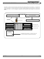
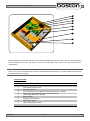
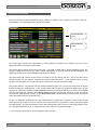
The MCU is a wall mounted connection panel which the mechanical floor unit is wired to. It contains the
various components to acquire data from the sensors during braking and control relays for starting and
stopping the rollers. It has an emergency stop button and main power switch located on one side of the
panel.
Emergency switch + Main switch
Wall mounted connection / control box
Measuring roller
Measuring roller
Slip detection roller
BSS2000
Side-Slip Meter
D412 Roller
Braketester
The BSS2000 Side-Slip Meter is a separate device and
can easily be added to the D412 Roller Braketester.
Wall mounted LCD display unit
GCP – Control System
Remote Control

DOC: BOS0481
D412 / D412+MC1 USER MANUAL
12 / 93
ENGLISH
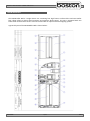
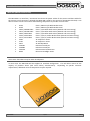
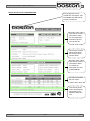
The D412B Roller Bed is a single chassis unit containing four high friction surface rollers and two smaller
free rolling rollers to detect wheel presence and measure wheel speed. The unit is equipped with two
brake force measurement sensors and can be fitted with an optional vehicle weighing system.
A general layout of the D412B Roller Bed is shown below.-
D412B Roller Bed

DOC: BOS0481
D412 / D412+MC1 USER MANUAL
13 / 93
ENGLISH
Component Table
Item
Description
Quantity
1
Tacho roller
2
2
Front roller
2
3
Chassis
1
4
Motor 230/400V 3kW
2
5
Connection PCB Enclosure
1
6
Connection Box Support Bracket
1
7
Force Transducer
2
8
Torque Arm
2
9
Bearing Housing
4
10
Chain Roller
4
11
Protection Plate
2
12
Side Covers
2
13
Detection Frame LEFT
1
14
Rear Roller
2
15
Centre Cover Plate
1
16
Connection PCB
1
17
Ground Connector
1
18
Drive Shaft Spacer
2
19
Spring Extension
2
20
Tacho Stop Block
2
21
Rubber Stop
2
22
Proximity Switch
2
23
Detection Frame RIGHT
1
24
End Chassis
2

DOC: BOS0481
D412 / D412+MC1 USER MANUAL
14 / 93
ENGLISH
The MCU-090 is an interface / connection box where the power cables for the motors and data cables for
the sensors are all connected. Although the MCU-090 is used for the control of the D412B roller bed, it can
also be used to connect and control the following components to provide a full test lane.-
• R102 Class 1,2 Motorcycle Roller Brake Tester
• R103 Class 1,2 Motorcycle Roller Brake Tester
• D402 / D402W+MC1 Class 1,2,3,4 Roller Brake Tester (Manual and Auto Testing)
• D412 / D412W+MC1 Class 1,2,3,4 Roller Brake Tester (Manual and Auto Testing)
• D403 / D403+MC2 Class 1,2,3,4 Roller Brake Tester (Manual and Auto Testing)
• D702 / D702+MC3 Class 1,2,3,4,5L,7 Roller Brake Tester (Manual and Auto Testing)
• D712 / D712+MC3 Class 1,2,3,4,5L,7 Roller Brake Tester (Manual and Auto Testing)
• S402 3T Suspension Tester
• S702 4T Suspension Tester
• SS02 4T Side-Slip Meter
• AGS200 Exhaust Gas Analyser
• AGS688 Exhaust Gas Analyser
• OPA100 Exhaust Diesel Smokemeter
• B502 Electronic Headlight Tester
NOTE
Some items listed above may be under development.
In most cases the MCU-090 will be supplied in standard configuration. This will allow control of the
majority of products above (and some others) simultaneously. Depending on specific customer
requirements, additional internal components may be required.
MCU-090 (Master Control Unit)

DOC: BOS0481
D412 / D412+MC1 USER MANUAL
15 / 93
ENGLISH
The MCU-090 is connected to the GCP using a standard USB A-B connection cable. Older versions of Boston
Control Platforms may also be used to control the MCU-090, check with your local distributor for
compatibility.
NOTE
There are no user serviceable parts inside the MCU-090 and all maintenance / repairs should be carried out
by approved Boston engineers.
Component Table
Item
Description
1
Connection Interface Card
2
Powered USB Hub
3
Data Acquisition Card 1 (Optional second card can be installed)
4
Relay Card 1 (Optional second card can be installed)
5
Low Voltage Connection Din Rail
6
Power Supply
7
Emergency Stop Button
8
Main Power Switch
9
High Voltage Relay Din Rail
2
8
5
3
6
4
1
9
7

DOC: BOS0481
D412 / D412+MC1 USER MANUAL
16 / 93
ENGLISH
The GCP is the computer control station that connects to the MCU-090 via USB. It is a separate unit and
can be supplied in different configurations, but in most cases it is wall mounted with a display monitor and
mouse / keyboard (GCP1). A breakdown of the GCP main standard supply components is listed below.-
Mini Industrial PC with Windows OS and Internal Wifi
Boston Software SW900
Optical PC Mouse
PC Keyboard
Widescreen LED Monitor
Laser Printer
Wall mount bracket or rolling stand
The GCP can also be supplied as a mobile unit using one of Boston’s rolling cabinet stands.
GCP3 - Circular Drum-Type Mobile Stand (as shown below)
GCP2 - Standard Mobile Stand
In all cases, the GCP can also be fitted with a second display monitor up to 60” in size. Please contact
Boston or your local sales / service agent for further information.
This manual only covers the Braketester software program; another manual is available separately detailing
the operation and functions of the SW900 software installed on the GCP.
BPC-0951 Mini PC
TRO-220 Mobile Stand
GCP (Global Control Platform)

DOC: BOS0481
D412 / D412+MC1 USER MANUAL
17 / 93
ENGLISH
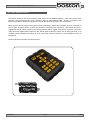
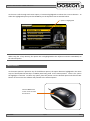
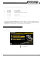
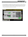
The remote control is the most commonly used control for the SW900 software. It has many of the same
functions as the keyboard but from a wireless range of approximately 50m. There is a separate User
Manual available for the Boston RF Remote Control, but the main functions are covered here.
Many remote controls operate using infra-red (IR) technology. Whilst being reliable, they are restricted to
‘line-of-sight’ operation which in some environments can make them impractical. The Boston RFC-95 is a
ruggedized control, ideally suited for the testing industry where rugged protection is required. It operates
using the latest Zigbee Radio Frequency (RF), which unlike IR doesn’t require line of sight operation. This
provides greater flexibility and allows it to be used from inside the vehicle to control different items of
equipment.
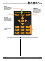
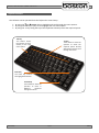
The RFC-95 button functions are shown below.
RFC-95 (RF Remote Control)

DOC: BOS0481
D412 / D412+MC1 USER MANUAL
18 / 93
ENGLISH
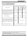
Button
Associated keyboard Function
ESC
ESCAPE
TAB
TAB
MM
MAIN MENU (SW900 Software only)
ARROW UP
ARROW UP
ARROW DOWN
ARROW DOWN
ARROW LEFT
ARROW LEFT
ARROW RIGHT
ARROW RIGHT
OK
ENTER
F1
FUNCTION KEY F1
F2
FUNCTION KEY F2
F3
FUNCTION KEY F3
F4
FUNCTION KEY F4
F5
FUNCTION KEY F5
F6
FUNCTION KEY F6
F7
FUNCTION KEY F7
F8
FUNCTION KEY F8
F9
FUNCTION KEY F9
‘TAB’ Key
This button duplicates
the ‘Tab’ key function on
the main keyboard.
‘ESC’ Button
This button duplicates
the ‘ESC’ key function
on the main keyboard.
‘MM’ Button
This button returns the
operator to the Main
Menu (only for Boston
SW-900 software).
Arrow Keys
These buttons duplicate
the arrow key functions
on the main keyboard.
‘F’ Keys
These buttons duplicate
the ‘F’ key functions on
the main keyboard.
‘OK’ Key
This button duplicates
the ‘ENTER’ key
function on the main
keyboard.
Transmission LED
The LED illuminates to
confirm any key press.

DOC: BOS0481
D412 / D412+MC1 USER MANUAL
19 / 93
ENGLISH
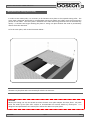
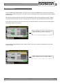
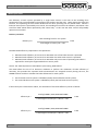
In order to test motorcycles, it is necessary to fit the MC1 cover plate to the required testing roller. The
cover plate is designed specifically to accommodate motorcycle wheels and safely cover the unused open
portion of the rollers. The cover plate is attached to the roller bed using two bolts and can be fitted very
quickly. It contains two hinges allowing the plate to ‘swing’ into place without the need to permanently
remove from the roller bed.
To fit the cover plate, refer to the illustration below.-
NOTE
The MC1 is a foot plate and is not intended for vehicles to drive over.
CAUTION
Motorcycle testing can only be carried out when the MC1 cover plate adapter has been fitted. The plate
limits the width of the open roller surface to accommodate the narrow wheels of motorcycles. It is
dangerous and prohibited to test motorcycles without the MC1 cover plate fitted.
MC1 (Motorcycle Testing Cover Plate)

DOC: BOS0481
D412 / D412+MC1 USER MANUAL
20 / 93
ENGLISH
In This Chapter
Power On (MCU-090) 20
Power On (BPC-091) 21
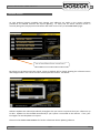
Menu Navigation 21
Mouse Control 22
Keyboard Control 23
Software Version 24
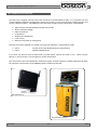
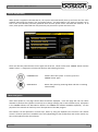
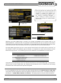
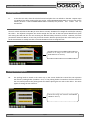
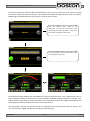
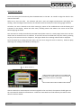
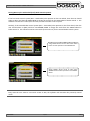
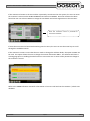
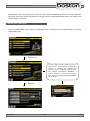
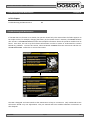
The MCU-090 has a Main Power switch and Emergency Stop button on the side of the cabinet. The Main
Power switch interrupts and isolates the power to the GCP control system and any other connected
equipment. The Emergency Stop button immediately stops all current operations and turns off the control
side of the system. It is usually left in the ‘running’ state and only used in the event of an emergency. The
operation of both these switches is shown below.-
Once power is applied to the MCU-090 the system is ready and waiting for instructions from the PC control
platform.
NOTE
In the wall-mount configuration, the power for the PC, monitor and printer is taken from the MCU-090.
When switching off the main power as described above, remember these items will also be switched off.
General Operation
Chapter 4
Power On (MCU-090)
MAIN POWER SWITCH - Isolates power from the
entire system and all other
connected equipment.
OPERATION - Rotate switch in clockwise /
anti-clockwise direction.
EMERGENCY STOP - Immediately stops all
operations and turns off
power to the control side
of the system.
OPERATION - Press switch to activate.
Rotate clockwise to de-
activate.
Page is loading ...
Page is loading ...
Page is loading ...
Page is loading ...
Page is loading ...
Page is loading ...
Page is loading ...
Page is loading ...
Page is loading ...
Page is loading ...
Page is loading ...
Page is loading ...
Page is loading ...
Page is loading ...
Page is loading ...
Page is loading ...
Page is loading ...
Page is loading ...
Page is loading ...
Page is loading ...
Page is loading ...
Page is loading ...
Page is loading ...
Page is loading ...
Page is loading ...
Page is loading ...
Page is loading ...
Page is loading ...
Page is loading ...
Page is loading ...
Page is loading ...
Page is loading ...
Page is loading ...
Page is loading ...
Page is loading ...
Page is loading ...
Page is loading ...
Page is loading ...
Page is loading ...
Page is loading ...
Page is loading ...
Page is loading ...
Page is loading ...
Page is loading ...
Page is loading ...
Page is loading ...
Page is loading ...
Page is loading ...
Page is loading ...
Page is loading ...
Page is loading ...
Page is loading ...
Page is loading ...
Page is loading ...
Page is loading ...
Page is loading ...
Page is loading ...
Page is loading ...
Page is loading ...
Page is loading ...
Page is loading ...
Page is loading ...
Page is loading ...
Page is loading ...
Page is loading ...
Page is loading ...
Page is loading ...
Page is loading ...
Page is loading ...
Page is loading ...
Page is loading ...
Page is loading ...
Page is loading ...
-
 1
1
-
 2
2
-
 3
3
-
 4
4
-
 5
5
-
 6
6
-
 7
7
-
 8
8
-
 9
9
-
 10
10
-
 11
11
-
 12
12
-
 13
13
-
 14
14
-
 15
15
-
 16
16
-
 17
17
-
 18
18
-
 19
19
-
 20
20
-
 21
21
-
 22
22
-
 23
23
-
 24
24
-
 25
25
-
 26
26
-
 27
27
-
 28
28
-
 29
29
-
 30
30
-
 31
31
-
 32
32
-
 33
33
-
 34
34
-
 35
35
-
 36
36
-
 37
37
-
 38
38
-
 39
39
-
 40
40
-
 41
41
-
 42
42
-
 43
43
-
 44
44
-
 45
45
-
 46
46
-
 47
47
-
 48
48
-
 49
49
-
 50
50
-
 51
51
-
 52
52
-
 53
53
-
 54
54
-
 55
55
-
 56
56
-
 57
57
-
 58
58
-
 59
59
-
 60
60
-
 61
61
-
 62
62
-
 63
63
-
 64
64
-
 65
65
-
 66
66
-
 67
67
-
 68
68
-
 69
69
-
 70
70
-
 71
71
-
 72
72
-
 73
73
-
 74
74
-
 75
75
-
 76
76
-
 77
77
-
 78
78
-
 79
79
-
 80
80
-
 81
81
-
 82
82
-
 83
83
-
 84
84
-
 85
85
-
 86
86
-
 87
87
-
 88
88
-
 89
89
-
 90
90
-
 91
91
-
 92
92
-
 93
93


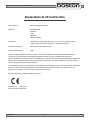
Boston D412 User manual
- Type
- User manual
- This manual is also suitable for
Ask a question and I''ll find the answer in the document
Finding information in a document is now easier with AI
Other documents
-
 Sun Mountain Micro Cart User manual
-
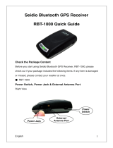 Seidio RBT-1000 User manual
-
TOA HY-BC1 Specification Data
-
 Sun Mountain Micro Cart User manual
-
Avid Technology VENUE D-Show Sidecar User manual
-
Rasonic RSB-BC2 User manual
-
-
 PPA BC1 - Plastic Chain Owner's manual
-
 Digital Tigers SideCar MMS Series User manual
-
NCR 7705 Kit Instructions


