Page is loading ...

803341NZ - HydroTap Taps Install Instructions 09.18 v2.11 Page 1 of 24
Installation Instructions
®
Zenith HydroTap Taps
HydroTap Classic
HydroTap Elite
HydroTap Arc/Cube
Classic All-In-One
Celsius All-In-One
Celsius Arc/Cube
Mixer Classic/Arc/Cube

Page 2 of 24 803341NZ - HydroTap Taps Install Instructions 09.18 v2.11
Notes

803341NZ - HydroTap Taps Install Instructions 09.18 v2.11 Page 3 of 24
1 - HydroTap Classic & Elite ................................................ 6
2 - HydroTap Arc / Cube ...................................................... 8
3 - Mixer Tap ...................................................................... 12
4 - Classic All-In-One Tap .................................................. 14
5 - Celsius All-In-One Tap .................................................18
6 - Celsius Arc / Cube ....................................................... 21
Contents

Page 4 of 24 803341NZ - HydroTap Taps Install Instructions 09.18 v2.11
Tap Options
A range of HydroTap taps are offered to suit the customer’s needs.
HydroTap Classic, Elite, HydroTap Arc and HydroTap Cube are standalone taps compatible with the
HydroTap undersink unit, offering instant boiling, chilled and/or sparkling water.
Classic, Arc and Cube Mixer Tap range may be used in conjunction with the standalone taps above to
provide mixed hot and cold water.
Classic All-In-One and Celsius All-In-One offer combinations of boiling, chilled and/or sparkling together
with an integral mains water mixer.

803341NZ - HydroTap Taps Install Instructions 09.18 v2.11 Page 5 of 24
Tap
Benchtop/Sinktop hole
diameter required
Recommended dispensing
distance
HydroTap Classic 35 mm 116 mm
Elite 35 mm 116 mm
HydroTap Arc/Cube 35 mm 171 - 174 mm (Extended)
Classic All-In-One 50 mm 211 mm
Celsius All-In-One 50 mm 242 - 250 mm
Celsius Arc/Cube 35 mm 220 mm
Mixer - Classic 35 mm 270 mm
Mixer - Arc/Cube 35 mm 220 mm
Note:
These instructions are provided for the installation of HydroTap taps only.
This book must be read in
conjunction with the undersink HydroTap Installation Manual and the User Manual.
For new installations, it is recommended to fit the tap prior to installing the undersink unit.
Special Tools Required:
In addition to normal tools, the following will be required:
•
35mm/50mm diameter sheet metal hole punch for sink tops (not supplied)
•
35mm/50mm diameter hole saw for timber bench tops (not supplied)
•
42mm AF tube spanner or wrench (not supplied) for fixing tap assembly (Celsius Arc/Cube)
Installation Specification
Dispensing distance
116
116
211

Page 6 of 24 803341NZ - HydroTap Taps Install Instructions 09.18 v2.11
1.2
BENCH TOP
Ø35mm
Single
Bowl
35mm
HOLE
Apply a light smear of silicon sealant on the underside
of the black plastic spacer, to ensure a watertight seal.
Fit the spacer and pass all the hoses, tubes and USB
cable through the 35mm hole. Position the tap so that
it discharges into the sink.
From under the sink/bench, t the stainless steel
washer and spider clamp to the all-thread rod, and
secure with the nut. The washer is formed similarly
to a spring washer. It will atten once the assembly is
tightened.
Note: feed each of the three tubes and USB cable
evenly in between the legs of the spider clamp.
Note: If the flow rate is too fast, insert the
Teflon restrictor into the silicon Hot Outlet tube
6mm NUT
SPIDER CLAMP
STAINLESS
STEEL WASHER
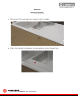
1 - HydroTap Classic & Elite
HydroTap Classic Elite
1.1
Position the tap such that it dispenses into the sink
bowl with ample clearance for a cup or tea pot.
Alternatively, the tap could be mounted away from the
sink using a font, available as an accessory.
Cut a 35mm hole in the bench / sink top.
BLACK
PLASTIC
SPACER
A
M6 ALL-THREAD
ROD
TEFLON FLOW
RESTRICTOR

803341NZ - HydroTap Taps Install Instructions 09.18 v2.11 Page 7 of 24
Installation Instructions - HydroTap Classic & Elite
Incoming
water
Blue hose to chilled
water outlet
Red hose to boiling
water outlet
Clear hose to Vent
1.3
Typical HydroTap Installation
RED
CLEAR
BLUE
BRAIDED
USB
CHILLED
OUTLET
MAINS
IN
MIXER
OUT
MIXER
IN
BOILING
OUT
BYPASS
IN
VENT
BYPASS
OUT
Note: All silicon
tubes must be cut
to size. They must
have a constant fall
back to the unit.
Note:
- Mains hose length
is 750mm
- Plug and cord
length is 1800mm
Position the under
sink unit close to
the outlet tap, within
reach of the hose
and cord lengths
supplied

Page 8 of 24 803341NZ - HydroTap Taps Install Instructions 09.18 v2.11
2 - HydroTap Arc/Cube
The HydroTap Arc/Cube has a spout that may be fixed in one of 6 angular positions and fixed in one of two
height positions. The spout is fixed and does not swivel.
NOTE: The tube kit must be fitted after the HydroTap has been mounted on the benchtop or sink. Refer to
the tube kit assembly instructions, supplied with the tap kit.
2.1 Adjust spout position
1. Remove the 2 x spout locating screws and lower the spout to expose the plastic spring clip
NOTE: The plastic spring clip has two internal dimples that may be positioned in the 6 upper or 6 lower,
pre drilled holes in the spout (see diagrams below and sections 2.2 & 2.3)
2. To reposition the spout, gently spread the plastic spring clip to release the dimples from the spout
holes. When released, slide the clip on the spout so that it ends up between the two rows of holes.
3. Rotate the plastic clip on the spout to orient the dimples, so they are in line with the newly selected
holes.
NOTE: When determining which of the 6 holes are required for the new spout height and orientation,
check the new plastic clip position will clear the undercut and that the wiring loom will not be pinched,
when assembled.
4. Slide the plastic clip up/down to engage with the selected holes, making sure the two dimples engage
simultaneously with the two selected holes.
NOTE: The clip will not fit correctly if one dimple engages before the other. Both dimples must engage at
the same time.
5. With the clip fitted to the newly selected holes,
carefully raise the spout (ensure the USB cable is a
neat fit in the undercut and is located between the
open ends of the clip) until the clip locating holes are
in line with the spout locating screws.
6. Replace the 2 x locating screws.
7. If mounting on an uneven surface, apply a light
smearing of silicon sealant on the O ring to ensure a
watertight fit. (See fig. 2.4)
8. Pass the assembly through the 35mm hole and
position the tap so it discharges into the sink.
9. Fit the lower rubber seal to the threaded extension.
10. Secure the tap in position with the metal washer and
nut.
11. Fit the tube kit, as supplied.
Spout locating
screws (2)
Plastic spring
clip
Upper locating
positions
Lower locating
positions
Clip locating
holes (2)
Undercut
for USB
Plastic spring clip
Dimples

803341NZ - HydroTap Taps Install Instructions 09.18 v2.11 Page 9 of 24
Installation Instructions - HydroTap Arc / Cube
A A
Left Hand Control Right Hand Control
B
C
C
B
50mm
2.2 Height adjustment (Fixed position options)
O-RING
LOWER
RUBBER
WASHER
METAL WASHER
NUT
2.4 Mounting
Cut a 35mm hole in the bench / sink top.
BENCH TOP
Ø35mm
NOTE: To reduce the risk of scalding, Position A should not be selected with Boiling Water units.
2.3 Angular adjustment (Fixed position options)

Page 10 of 24 803341NZ - HydroTap Taps Install Instructions 09.18 v2.11
John Guest fittings (insertion and removal)
NOTE: Be careful when cutting the poly tube so that there are no rough edges and that the tube is not distorted.
1. Use a sharp knife to ensure the tube has a clean, straight
edge. Do not cut at an angle.
2. Remove any swarf or unwanted material.
3. Push the tube into the John Guest fitting making sure all
connections to the John Guest fittings are pushed in past the
“O”ring to full depth, at least 15-16mm.
4. Check for a good joint by pulling back on the tube. If the tube
comes out of the fitting, repeat the above step.
5. To remove the tube, press the collet into the fitting and at the
same time pull back on the tube.
Installation Instructions - HydroTap Arc / Cube
2.5 Tube kit assembly
NOTE:
The L/H & R/H
positions of
the three way
silicon tube are
interchangeable
Type C
Chilled Sparkling
Used with BCS only
Type B
Chilled
Type A
Boiling
Type D
Sparkling
Type E
Chilled / Ambient
Red
Silicon
Blue
Silicon
Blue / White
LLDPE
White
LLDPE
Blue
LLDPE
Type F
S/S Tube
Three way
silicon tube
S/S tube
20mm
insertion
Fig. 1
Clamp Herbie
clip near the end
of the three way
silicon tube
Fig. 2
General Fitting Instructions
Once the ARC and CUBE HydroTaps have been secured to the benchtop or sink, it will be necessary to
connect the relevant tube kit to the three way silicon tube as follows: (See below for specific tube kit assembly
instructions)
•
Insert the 1/4” Blue and White JG tubes into their respective JG fittings as shown above (Type C-E)
•
Ensure all connectors and tubes, are pushed fully home into the JG fittings (see below).
•
Assemble tubes in accordance with the instructions overleaf. Check the insertion depth as shown in
Fig.1.
•
For Maximum grip on all three connectors, ensure the Herbie clip is clamped close to the end of the
three way silicon tube and aligned with the central axis, as shown in Figs.1 & 2
Axial alignment
of clips
Herbie clip
orientation:
align with axis

803341NZ - HydroTap Taps Install Instructions 09.18 v2.11 Page 11 of 24
Installation Instructions - HydroTap Arc / Cube
Important: The labels are printed on a clear lm. It is important to ensure that you do
not touch the adhesive side of the label when removing the label from the white backing
strip, to prevent nger marks visible after the label is positioned on the tap.
Procedure:
• Clean the area on the tap where you plan to mount the label i.e. Area 1 (Top) or
Area 2 (Left or Right Hand Side).
• Choose which label is appropriate for your tap.
• For BC; BA; B & CS labels, trim inside the blue line to the left of the chosen label,
• Locate the pre-cut edge on the white backing and peel the clear label away from the
white backing paper, to expose the adhesive on your chosen label.
• NOTE: DO NOT TOUCH THE ADHESIVE BACKING ON YOUR CHOSEN LABEL
• For the BCS label, do not trim any of the labels, just peel the backing paper from
the pre-cut edge to expose the adhesive on the BCS label.
• For the Chilled label, trim to the left of the CS label before peeling off the backing
paper
• After carefully peeling the white backing paper off the label, position one edge of the
clear label, on the tap. Make sure the label is centred and squarely positioned.
• Cut inside the blue line of the label, to free it from the strip.
• Press the label firmly in position.
Area 1
Area 2
BOILING
CHILLED
SPARKLING
BOILING
CHILLED
BOILING
AMBIENT
BOILING
CHILLED
SPARKLING
CHILLED
Pre-cut edge on
backing paper
Outer edge
Outer edge
2.6 Attach Label
Working from inside the cupboard, follow the directions for the relevant installation:
Boiling Kit:
Fit the Type A tube assembly into the L/H or R/H side of the three way silicon tube.
Fit the Type F tube into the other side of the three way silicon tube.
Boiling Ambient Kit:
Fit the Type A tube assembly into the L/H or R/H side of the three way silicon tube.
Fit the Type E tube assembly into the other side of the three way silicon tube.
Boiling Chilled Kit:
Fit the Type A tube assembly into the L/H or R/H side of the three way silicon tube.
Fit the Type B tube assembly into the other side of the three way silicon tube.
Chilled Kit:
Fit the Type B tube assembly into the L/H or R/H side of the three way silicon tube.
Fit the Type F tube into the other side of the three way silicon tube.
Chilled Sparkling Kit:
Fit the Type D tube assembly into the L/H or R/H side of the three way silicon tube.
Fit the Type E tube assembly into the other side of the three way silicon tube.
Boiling Chilled Sparkling Kit:
Fit the Type A tube assembly into the L/H or R/H side of the three way silicon tube.
Fit the Type C tube assembly into the other side of the three way silicon tube.
Finally, secure the Herbie clip around the base of the silicone tube by hand - note orientation of Herbie clip,
see Fig. 2. Then give a nal squeeze with pliers to ensure a tight t.
Blue lines

Page 12 of 24 803341NZ - HydroTap Taps Install Instructions 09.18 v2.11
Position the tap such that it dispenses into the sink bowl
with ample clearance for a cup or tea pot.
Cut a 35mm hole in the bench / sink top.
SINK TOP
35mm
BRAIDED HOSE x 3
White/No colour:
External mains water supply
Red band: Mixer OUT
Blue band: Mixer IN
3 - Mixer Tap
CLASSIC, ARC, CUBE
3.2
•
Fit the O-ring into the recess on the underside of the
Mixer tap. If mounting on an uneven surface, apply a
light smear of silicone sealant to the O-ring, to ensure a
watertight seal.
•
Pass the tap tubes and threaded extension through the
35mm hole and position the tap so that it discharges into
the sink.
•
Fit the lower rubber washer to the threaded extension.
•
Secure the tap in position with the metal washer and nut.
•
Affix the three hoses to the tap. Match the hose colours
to the coloured bands on the copper extension tubes.
Arc Mixer Tap
For use with
Classic or Arc HydroTap
NOTE: For low pressure installations
Replace the normal 804178-Aerator with an
805734-ow
straightener in the spout of a v
ented
Zenith mixer tap.
3.1
Classic Vented
Mixer Tap
For use with
Classic/Arc/Cube HydroTap
Cube Mixer Tap
For use with
Classic or Cube HydroTap
O-RING
LOWER
RUBBER
WASHER
METAL WASHER
NUT
804178 805734

803341NZ - HydroTap Taps Install Instructions 09.18 v2.11 Page 13 of 24
Installation Instructions - Mixer Tap
3.3 Typical HydroTap 4-in-1 Installation
COLD isolation valve
(not supplied)
HydroTap
Mixer
Connections
RED
CLEAR
BLUE
WHITE
Flow restrictor valve
and Tee piece
(supplied)
POWER
CORD
USB
CHILLED
OUTLET
MAINS
IN
MIXER
OUT
(Red)
MIXER
IN
(Blue)
BOILING
OUT
BYPASS
IN
VENT
BYPASS
OUT
Note:
- Mains hose length
is 750mm
- Plug and cord
length is 1800mm
Position the under
sink unit close to
the outlet tap, within
reach of the hose
and cord lengths
supplied
Note: All silicon
tubes must be cut
to size. They must
have a constant fall
back to the unit.
Note
:
The mixer tap requires a ow restrictor valve (supplied) to be tted in the cold water supply line,
from the isolation valve tee piece, to the mixer tap.
Blue hose to chilled
water outlet
Red hose to boiling
water outlet
Clear hose to Vent

Page 14 of 24 803341NZ - HydroTap Taps Install Instructions 09.18 v2.11
4 - Classic All-In-One Tap
4.2
• Fit the O-ring seal to the base of the tap. If mounting
on an uneven surface, apply a light smear of silicone
sealant to the O-ring, to ensure a watertight seal.
•
Pass the USB cable and tubes through the 50mm hole
and position the tap so that it discharges into the sink.
• Thread the cable and silicon tubes through the circular
clamp block (see figures 4.3 & 4.5) and fix with nut.
• Affix the braided hoses (see figures 4.4 & 4.5).
For A-I-O tap:
50mm hole
Double Bowl
4.1
SINK TOP
50mm
Classic All-In-One Tap
Vented or Mains
Position the tap such that it dispenses into the sink
bowl with ample clearance for a cup or tea pot.
Cut a 50mm hole in the bench / sink top.
CLAMP
BLOCK
Braided
hoses
Extension
tubes
Typical Vented assembly
O-ring

803341NZ - HydroTap Taps Install Instructions 09.18 v2.11 Page 15 of 24
Mains braided hose positions
RED: Hot IN from
hot water system
BLUE
Mains IN
4.3
Installation Instructions - Classic All-In-One Tap
Vented silicon tube positions
Mains silicon tube positions
Insert Silicon Tubes through Clamp Block (viewed from underneath)
BLUE mark
WHITE mark
BLUE mark RED mark
R
SILICON TUBES
USB CABLE
R
C
B
C
B
Working from inside the cupboard, screw the braided hoses to the extension tubes. Ensure the seals on
the end of the hoses are lubricated prior to assembly.
Check the correct position for Hot and Cold connections by matching the colours on the braided hoses
with the coloured markings on the copper extension tubes and on the clamp block (as indicated). Make
sure all tubes and hoses are firmly secured.
Test for leaks after all the connections have been secured.
Vented braided hose positions
4.4
Affix Braided Hoses through Clamp Block (viewed from underneath)
BLUE to HydroTap
Mixer IN
WHITE
Mains IN
RED from HydroTap
Mixer OUT
Thread the USB cable and silicon tubes through the circular clamp block. Check the tube colour alignment
with the diagram below.
Clamp the assembly in position using the threaded fixing nut (see fig. 4.5).

Page 16 of 24 803341NZ - HydroTap Taps Install Instructions 09.18 v2.11
4.5
Installation Instructions - Classic All-In-One Tap
FIXING NUT
CLAMP BLOCK O-RING
BLUE to Chiller
connection
CLEAR
to vent
RED to Boiling
connection
From Mixer
OUT
RED to Boiling
connection
BLUE to Chiller
connection
Mains IN
From HWS
connection
Mains IN
To Mixer
IN
R
R
C
B
B
Vented Mains
Assembled Clamp Block
Note:
If the ow rate is too fast, a teon ow restrictor is provided
with the tap.
• Cut the red silicon tube 75mm (minimum) from the bottom of
the base of the All-In-One tap.
• Insert the Teon Restrictor about 20mm into the upper seg-
ment of the red silicon tube which connects to the tap.
• Insert the black plastic outlet bush between the two pieces
of red silicon tubes that was cut.
TEFLON FLOW
RESTRICTOR
BLACK PLASTIC
OUTLET BUSH

803341NZ - HydroTap Taps Install Instructions 09.18 v2.11 Page 17 of 24
Installation Instructions - Classic All-In-One Tap
4.6
Typical All-In-One Mains Installation with Booster (optional)
Booster
Tee piece &
connector strainer
(supplied)
Booster
RED
CLEAR
BLUE
BRAIDED
USB
CHILLED
OUTLET
MAINS
IN
MIXER
OUT
MIXER
IN
BOILING
OUT
BYPASS
IN
VENT
BYPASS
OUT
Note:
- Mains hose length
is 750mm
- Plug and cord
length is 1800mm
Position the under
sink unit close to
the outlet tap, within
reach of the hose
and cord lengths
supplied
Note: All silicon
tubes must be cut
to size. They must
have a constant fall
back to the unit.

Page 18 of 24 803341NZ - HydroTap Taps Install Instructions 09.18 v2.11
5 - Celsius All-In-One Tap
5.1
BENCH TOP
Ø 50mm
5.2
•
Pass all the hoses, tubes and USB lead
through the 50mm hole.
•
Ensure the black rubber seal is correctly
positioned to give a water tight seal
•
Secure with the steel washer and large nut
from inside the cupboard space.
•
Connect silicon hoses to the 3-way tube as
shown in Fig. 5.3 & 5.4.
•
Affix the braided hoses for hot and cold
mains water supply.
For Celsius A-I-O
Tap 50mm hole
Double Bowl
O-RING SEAL
BLACK RUBBER
SEAL
STEEL WASHER
BRASS NUT
USB PLUG
HOT & COLD
BRAIDED HOSES
Position the tap such that it dispenses into the sink
bowl with ample clearance for a cup or tea pot.
Cut a 50mm hole in the bench / sink top.
Celsius All-In-One Tap

803341NZ - HydroTap Taps Install Instructions 09.18 v2.11 Page 19 of 24
FROM BOILING OUTLET
AT UNDERSINK UNIT
5.3 Plumbing Connection
FROM CHILLED OUTLET
AT UNDERSINK UNIT.
ADD SPARKLING, IF IN-
CLUDED (SEE FIG 5.4)
FROM STEAM VENT
OUTLET OF UNDERSINK
UNIT
3 WAYS MULTI
CHANNEL
BOTTOM END OF
3-WAY TUBE
3 STAINLESS
STEEL TUBES
STEAM
VENT
BOILING
OUTLET
CHILLED
OUTLET
BRASS NUT
USB PLUG
COLD MAINS HOT MAINS
JG STRAIGHT
CONNECTOR
BRAIDED HOSE
FOR MIXED
WATER
BOILING
STEAM
VENT
CHILLED
SPARKLING
JG Straight
Connector
LLDPE Tube
Y connector
5.4 BCS MODEL
Installation Instructions - Celsius All-In-One Tap
BC MODEL

Page 20 of 24 803341NZ - HydroTap Taps Install Instructions 09.18 v2.11
Installation Instructions - Celsius All-In-One Tap
5.5
Typical Celsius All-In-One Mains Installation with Booster (optional)
Booster
Tee piece and
connector strainer
(supplied)
Booster
RED
CLEAR
BLUE
BRAIDED
USB
CHILLED
OUTLET
MAINS
IN
MIXER
OUT
MIXER
IN
BOILING
OUT
BYPASS
IN
VENT
BYPASS
OUT
Note:
- Mains hose length
is 750mm
- Plug and cord
length is 1800mm
Position the under
sink unit close to
the outlet tap, within
reach of the hose
and cord lengths
supplied
Note: All silicon
tubes must be cut
to size. They must
have a constant fall
back to the unit.
/