Page is loading ...

PC-HELPER
N Series for USB
RS-422A/485 4ch Isolated Serial I/O Unit
COM-4PDHN-USB
User’s Guide
CONTEC CO., LTD.

COM-4PDHN-USB
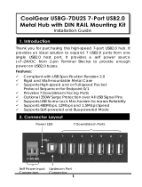
Check Your Package
Thank you for purchasing the CONTEC product.
The product consists of the items listed below.
Check, with the following list, that your package is complete. If you discover damaged or missing items,
contact your retailer.
Product Configuration List
- Product [COM-4PDHN-USB] …1
- Rubber feet…4
- 3-pin power connector …1
- 5-pin connector for RS-422A/485 communication…4
- AC cable (1.8m) …1
- USB cable (1.8m) …1
- USB cable attachment on the main product’s side (For Mini B connector side) …1
- AC adapter …1
- Disk *1 [COM Setup Disk] …1
- First step guide … 1
- Warranty Certificate …1
- Serial Number Label …1
*1 The bundled disk contains the driver software and User’s Guide (this guide).
Warranty Certificate
Serial Number Label
Product
Disk
[COM Setup Disk]
First step guide
USB cable (1.8m)
USB cable attachment
on the main product’s side
Rubber feet
5-pin connector
for RS-422A/485
communication
3-pin
power connector
AC cable
AC adapter
Warranty
Certificate

ii
COM-4PDHN-USB
Copyright
Copyright 2017 CONTEC CO., LTD. ALL RIGHTS RESERVED.
No part of this document may be copied or reproduced in any form by any means without prior written
consent of CONTEC CO., LTD.
CONTEC CO., LTD. makes no commitment to update or keep current the information contained in this
document. The information in this document is subject to change without notice.
All relevant issues have been considered in the preparation of this document. Should you notice an
omission or any questionable item in this document, please feel free to notify CONTEC CO., LTD.
Regardless of the foregoing statement, CONTEC assumes no responsibility for any errors that may appear
in this document or for results obtained by the user as a result of using this product.
Trademarks
MS, Microsoft, Windows and MS-DOS are trademarks of Microsoft Corporation. Other brand and
product names are trademarks of their respective holder.

COM-4PDHN-USB
iii
Table of Contents
Check Your Package .................................................................................................................................... i
Copyright ...................................................................................................................................................... ii
Trademarks ................................................................................................................................................... ii
Table of Contents ........................................................................................................................................ iii
1. BEFORE USING THE PRODUCT 1
About the Product ........................................................................................................................................ 1
Features ................................................................................................................................................. 1
Support Software .................................................................................................................................. 2
Accessories (Option) ............................................................................................................................ 2
Customer Support ........................................................................................................................................ 3
Web Site ................................................................................................................................................ 3
Limited One-Year Warranty ....................................................................................................................... 3
How to Obtain Service ................................................................................................................................ 3
Liability ........................................................................................................................................................ 3
Safety Precautions ....................................................................................................................................... 4
Safety Information................................................................................................................................ 4
Handling Precautions ........................................................................................................................... 4
Environment ......................................................................................................................................... 6
Inspection .............................................................................................................................................. 6
Storage .................................................................................................................................................. 6
Disposal................................................................................................................................................. 6
2. SETUP 7
What is Setup? ............................................................................................................................................. 7
Installing the driver .............................................................................................................................. 7
Step 1 Installing the Software ..................................................................................................................... 8
Step 2 Installing the Hardware .................................................................................................................... 9
Name of each parts ............................................................................................................................... 9
Component Functions ........................................................................................................................ 10
Setting Transmission Mode ............................................................................................................... 10
Setting of Terminator ......................................................................................................................... 11
How to supply power to the product ................................................................................................. 13
Connecting the Product ...................................................................................................................... 14
Setting with the Found New Hardware Wizard ............................................................................... 16
Step 3 Initializing the Software ................................................................................................................ 17
Step 4 Operation check.............................................................................................................................. 18
Check Method..................................................................................................................................... 18
Using the Diagnostic Program for Serial Communications Port .................................................... 19

iv
COM-4PDHN-USB
If Setup fails to be performed normally ................................................................................................... 20
3. INSTALLATION AND CONNECTING WITH EXTERNAL DEVICES 21
Installation Method .................................................................................................................................... 21
Mounting on a DIN Rail .................................................................................................................... 21
Desktop Installation ........................................................................................................................... 23
Wall Installation ................................................................................................................................. 23
Installation Using the Magnet ........................................................................................................... 24
Steel wall installation ......................................................................................................................... 25
Installation Conditions .............................................................................................................................. 26
Connection Method ................................................................................................................................... 28
Interface Connector ............................................................................................................................ 28
Connector Pin Assignment ................................................................................................................ 28
Types of Cable and Example Connections .............................................................................................. 29
4. FUNCTION 31
Communication Function .......................................................................................................................... 31
Serial Data Transmission ................................................................................................................... 31
Send and Receive Data Buffers ......................................................................................................... 31
Automatic RTS Control Functions.................................................................................................... 31
Setting the Baud Rate......................................................................................................................... 32
5. ABOUT SOFTWARE 33
About standard COM driver software ...................................................................................................... 33
About Sample programs ............................................................................................................................ 33
Uninstalling the Driver Libraries .............................................................................................................. 34
6. ABOUT HARDWARE 35
Hardware specification .............................................................................................................................. 35
Physical dimensions .................................................................................................................................. 38

1. Before Using the Product
COM-4PDHN-USB
1
1.
Before Using the Product
This chapter provides information you should know before using the product.
About the Product
This product is an USB2.0-compliant product designed for extending RS-422A/485 compatible serial
communication functionality on your PC.
This product supports a baud rate of up to 921,600bps and has separate 128-byte / 384-byte buffer
memory for transmit and receive.
It also comes with a Windows driver, which allows products to be used as OS-standard COM ports.
Features
- Max. 921,600bps RS-422A/485 Serial Communication
This product has 4 channel RS-422A/485-standard serial ports. Baud rates from 300 to 921,600bps can be
set for each port. When using the bundled “Standard COM Driver Software”, baud rates from 300 to
921,600bps can be set. When data is transferred at the high speed, it may not be transferred normally,
depending on the use environment such as the external device and cable length used.
- Possibly used as Windows-standard COM ports, using the bundled driver library
Comes with a driver software that allows the products to be used under Windows in the same way as
COM ports on the PC.
Under Windows, the product supports the OS-standard Win32 API communication function as well as
Visual Basic MSComm.
- Each channel is equipped with separate 128-byte / 384-byte FIFO buffers for transmit and receive.
These are FIFO format, useful for high speed communications and to reduce the load to the CPU when
transmitting/receiving.
- Compatible to USB1.1/USB2.0
Compatible to USB1.1/USB2.0 and capable to achieve high speed transfer at Full Speed (12 Mbps).
- Compact Design
Compact design, 188.0(W) × 78.0(D) × 30.5(H), features flexibility in installation.
- Adapting terminal connecters make it easy to connect and install the product
The terminal connectors (screw type) make it easy to connect and install the product.
- Capable of adapting a wide-range power (12- 24VDC)
The product is capable of dealing with a wide range of power in the differing environments.
Power connector also has a FG terminal.
- Diverse installations such as screw fastening, magnet (option), DIN rail are possible
Installation on the floor / wall /ceiling is possible by screw fastening, magnet (option), rubber feet, etc.
In addition, DIN rail mounting mechanism is equipped as standard with the product, making it easy to
install the product within the panel or the device.

1. Before Using the Product
2
COM-4PDHN-USB
Support Software
You should use CONTEC support software according to your purpose and development environment.
Standard COM Driver Software
COM Setup Disk
(Bundled)
Under Windows, this software allows you to use the serial ports on the converter as if they were standard
COM ports on the PC. By connecting additional products, you can use COM ports in the range COM1 -
COM256.
Under Windows, the serial ports can be accessed using the standard Win32 API communication routines
(CreateFile( ), WriteFile( ), ReadFile( ), and SetCommState( ), etc.) The serial ports are also compatible
with the Visual Basic communication control (MSComm).
Supports the communication class of .NET
Framework (SerialPort class).
For more details on the supported OS, applicable language and new information, please visit the CONTEC’s Web site.
Accessories (Option)
AC adaptor (Input : 90 - 264VAC, output : 12VDC 1.0A) : POA201-10-2
DIN rail mounting power supply 15[w] : CPS-PWD-15AW12-01 *1
(Input: 100 - 240VAC, output: 12VDC 1.3 A)
Magnets for installation (Four Piece Set) : CPS-MAG01-4
*1 This needs to be accompanied by AC cable. A user is encouraged to purchase our recommended AC
cable (sold separately).
* Check the CONTEC’s Web site for more information on these options.

1. Before Using the Product
COM-4PDHN-USB
3
Customer Support
CONTEC provides the following support services for you to use CONTEC products more efficiently and
comfortably.
Web Site
https://www.contec.com/
Latest product information
CONTEC provides up-to-date information on products.
CONTEC also provides product manuals and various technical documents in the PDF.
Free download
You can download updated driver software and differential files as well as sample programs available in
several languages.
Note! For product information
Contact your retailer if you have any technical question about a CONTEC product or need its price,
delivery time, or estimate information.
Limited One-Year Warranty
CONTEC products are warranted by CONTEC CO., LTD. to be free from defects in material and
workmanship for up to one year from the date of purchase by the original purchaser.
Repair will be free of charge only when this device is returned freight prepaid with a copy of the original
invoice and a Return Merchandise Authorization to the distributor or the CONTEC group office, from
which it was purchased.
This warranty is not applicable for scratches or normal wear, but only for the electronic circuitry and
original products. The warranty is not applicable if the device has been tampered with or damaged
through abuse, mistreatment, neglect, or unreasonable use, or if the original invoice is not included, in
which case repairs will be considered beyond the warranty policy.
How to Obtain Service
For replacement or repair, return the device freight prepaid, with a copy of the original invoice. Please
obtain a Return Merchandise Authorization number (RMA) from the CONTEC group office where you
purchased before returning any product.
* No product will be accepted by CONTEC group without the RMA number.
Liability
The obligation of the warrantor is solely to repair or replace the product. In no event will the warrantor be
liable for any incidental or consequential damages due to such defect or consequences that arise from
inexperienced usage, misuse, or malfunction of this device.

1. Before Using the Product
4
COM-4PDHN-USB
Safety Precautions
Understand the following definitions and precautions to use the product safely.
Safety Information
This document provides safety information using the following symbols to prevent accidents resulting in
injury or death and the destruction of equipment and resources. Understand the meanings of these labels
to operate the equipment safely.
DANGER indicates an imminently hazardous situation which, if not avoided, will
result in death or serious injury.
WARNING indicates a potentially hazardous situation which, if not avoided, could
result in death or serious injury.
CAUTION indicates a potentially hazardous situation which, if not avoided, may
result in minor or moderate injury or in property damage.
Handling Precautions
Do not use the product where it is exposed to flammable or corrosive gas. Doing so may result in an
explosion, fire, electric shock, or failure.
- Do not strike or bend this product.
Otherwise, this may malfunction, overheat, cause a failure or breakage.
- Do not touch this product's terminals (USB connector, D-SUB connector) with your hands.
Otherwise, this may malfunction, overheat, or cause a failure.
If the terminals are touched by someone's hands, clean the terminals with industrial alcohol.
- Do not close the ventilation hole(s) of this product by, for example, placing an object. This may
cause overheating, malfunction, and/or failure of the product.
- Do not touch the external connector when the power is on.
Otherwise this may malfunction, overheat, cause a failure due to static electricity.
- Make sure that your PC can supply ample power to all this product connected.
Insufficiently energized products could malfunction, overheat, or cause a failure.
- The specifications of this product are subject to change without notice for enhancement and quality
improvement.
Even when using this product continuously, be sure to read the manual and understand the contents.
- Do not modify this product. CONTEC will bear no responsibility for any problems, etc., resulting
from modifying this product.
- Regardless of the foregoing statements, CONTEC is not liable for any damages whatsoever
(including damages for loss of business profits) arising out of the use or inability to use this
CONTEC product or the information contained herein.
- If you use this product in a noisy environment, attach a ferrite core to USB cable to stabilize the
operation. When attaching a ferrite core, coil it around once or more near the connector while leaving
it open, and then close it.
DANGER
WARNING
C
AU
TION
DA
NGER
CA
UTION

1. Before Using the Product
COM-4PDHN-USB
5
- Regarding “CE EMC Directive Class A Notice”
The ferrite core must be installed in interface connecting cable so that this product may suit the
above-mentioned standard.
Name
Maker
Turn
Quantity
Installation Site
KRFC-6
KGS
1
1
on USB cable at product
KRFC-9
KGS
2
1
on FG cable at product
Image diagram
FCC PART 15 Class A Notice
EN55032 Class A Notice
Warning: Operation of this equipment in a residential environment could cause radio interference.
This equipment has been tested and found to comply with the limits for a Class A digital device,
pursuant to part 15 of the FCC Rules. These limits are designed to provide reasonable protection
against harmful interference when the equipment is operated in a commercial environment.
This equipment generates, uses, and can radiate radio frequency energy and, if not installed and
used in accordance with the instruction manual, may cause harmful interference to radio
communications. Operation of this equipment in a residential area is likely to cause harmful
interference in which case the user will be required to correct the interference at his own expense.
NOTE
FCC WARNING
Changes or modifications not expressly approved by the party responsible for compliance could void
the user's authority to operate the equipment.
Ferrite core
Cable
TURN : 1
TURN : 2
TURN : 3
TURN : 4

1. Before Using the Product
6
COM-4PDHN-USB
Environment
Use this product in the following environment. If used in an unauthorized environment, this product may
overheat, malfunction, or cause a failure.
Operating temperature
-20 - 60°C
Humidity
10 - 90%RH (No condensation)
Corrosive gases
None
Floating dust particles
Not to be excessive
Inspection
Inspect the product periodically as follows to use it safely.
Be certain that the ventilation holes of this product are not closed and also no dust or foreign matter is
adhered to them.
Storage
When storing this product, keep it in its original packing form.
(1) Put this product in the storage bag.
(2) Wrap it in the packing material, and then put it in the box.
(3) Store the package at room temperature at a place free from direct sunlight, moisture, shock, vibration,
magnetism, and static electricity.
Disposal
When disposing of the product, follow the disposal procedures stipulated under the relevant laws and
municipal ordinances.
- Check that the connector has no dust
or foreign matter adhering.
COM-4P DHN -US B
USB I/OTe rmin al
Isol ated R S-422A /485 4ch I/O Unit
V+ V-
C
AUTION

2. Setup
COM-4PDHN-USB
7
2.
Setup
This chapter explains how to set up this product.
What is Setup?
Setup means a series of steps to take before the product can be used.
Different steps are required for software and hardware.
Installing the driver
This section enables you to prepare the software and hardware by following each step in this chapter with
the bundled disk “COM Setup Disk”. You can use the diagnosis program later to check whether the
software and hardware function normally.
Step 1 Installing the Software
Step 2 Setting the Hardware
Step 3 Initializing the Software
Step 4 Operation Check

2. Setup
8
COM-4PDHN-USB
Step 1 Installing the Software
Install software.
Run [\USB\COM-4CN-USB\Setup.exe] from the bundled disk.
(1) The screens below show the installation.Click [next].
(2) Accept the license agreement, then click [Next>].
(3) The setup is completed.

2. Setup
COM-4PDHN-USB
9
Step 2 Installing the Hardware
When using the product in the Windows environment, the OS needs to recognize the peripheral devices.
This is called hardware installation.
If you are using more than one product, be sure to complete the first installation, then install the
next one.
Name of each parts
Figure 2.1. Name of each parts
USB cable
attachment
For PC
Interface connector
USB Type A
LED indicator
COM-4PDHN-USB
USB I/OT
erminal
Isol at ed RS
-422A/485 4ch I/O Unit
V+
V-
Interface connector
CH1
CH2
CH3 CH4
USB2.0 (mini-B type)
12-24VDC
SW1
SW2 SW3
SW4

2. Setup
10
COM-4PDHN-USB
Component Functions
LED indicator
LED
Meaning
Status
POWER (Green)
*1
Power status
OFF: Power has not been supplied.
ON: Power has been supplied.
RxD (Yellow)
Reception status
Output status indication
OFF : Data has not been received by the RS-422A/485
ON : When receiving data by the RS-422A/485
TxD (Green) Transmission status Input status indication
OFF : Data has not been sent by the RS-422A/485
ON : When sending data by the RS-422A/485
*1 LEDs light up when both the external power supply and the USB cable are connected. Only with one of them connected, the lights will
not be on.
Setting Transmission Mode
The data transfer mode setting switch is used to switch between full duplex and half duplex and to specify
whether to use RTS/CTS in full duplex mode. Set the appropriate data transfer mode for the device with
which you are communicating.
Bits 3 - 5 corresponded to each channel are used to set the data transfer mode. Always set the bit 6 to
OFF.
Setting Procedure
Table 2.1. Setting Transmission Mode
The CTS signal of each channel is controlled by self-looping the RTS signal of the corresponding channel
in the product.
1 2 3 4 5 6
TERM MODE
ON
TERM
MODE
ON
1 2 3
4 5 6
Setting
mode
(SW1 - 4)
Transmission
mode
Half duplex
Full duplex

2. Setup
COM-4PDHN-USB
11
Setting of Terminator
The terminator setting switch controls whether or not a terminator is inserted into each signal line. Set the
terminators on or off in accordance with the devices with which you are communicating. The terminators
on the product are 100Ω resistors.
Setting Procedure
If you wish to use a terminator of other than 100Ω, set the bit 1 and 2 of corresponded channels OFF, and
insert an external terminator. The diagrams below show examples of terminator installation for half and
full duplex setting.
Table 2.2. Setting of Terminator
- Half-duplex
Figure 2.2. Party line connection
SW1 - 4
1 2 3 4 5 6
TERM MODE
RxD
TxD
ON
Setting
method
Not inserted
[Term OFF]
Figure 2.2 B to C
(Other than both
terminators of the line)
[A or D]
Terminator
(Bit 9)
Terminator
(Bit 9)
(A) (D)(C)(B)
[B or C]
SW2 SW2
SW2
1
2
3
4
5
6
O
N
TERM
MODE
1
2
3
4
5
6
O
N
TERM MODE
1
2
3
4
5
6
O
N
TERM MODE
RxDTxD
RxDTxD
RxDTxD
Inserted
Not inserted
Not inserted
SW1 - 4
SW1 - 4
SW1 - 4

2. Setup
12
COM-4PDHN-USB
- Full -duplex
Figure 2.3. Example Connection Oneself loop to RTS and CTS in Full Duplex
The figure below shows the circuit associated with the data transfer mode setting switch and terminator
setting switch. Each channel shares the same switch and the bits to be set are vary.
Figure 2.4. Setting Switch Circuits
RxD
TxD
Terminator (Bit 9)
Terminator (Bit 7)
Terminator (Bit 7) Terminator (Bit 9)
TxD
RxD
SW2 SW2
1
2
3
4
5
6
O
N
TERM
MODE
1
2
3
4
5
6
O
N
TERM MODE
RxD
TxD
RxD
TxD
Inserted Not inserted
SW1 - 4
SW1 - 4
TxD+
TxD-
RxD+
RxD-
RTS
DCD
DTR
DSR
RI
CTS
SIN
SOUT
Terminator
1/2W 100Ω
2 1
Terminator
3 4 5 6
Data transfer mode

2. Setup
COM-4PDHN-USB
13
How to supply power to the product
Connect to the external power using the power input connector of this product (suitable cable is AWG28 -
16). Even when using the commercial DC output power supply, follow the instruction described here.
Signal name
Meaning
FG
Frame ground
Vi- Power supply (GND)
Vi+
Power supply (12 – 24VDC±10%)
When using the provided AC adapter [POA201-10-2], please connect directly to the input terminals.
When using the provided 3-pin connector (MC1,5/3-ST-3,5, suitable cable: AWG28 - 16) to supply
power to this product, strip the end of the suitable cable and connect it with the connector firmly using a
screw, then insert it to the terminals.
Figure 2.5. Connecting the AC Adapter POA201-10-2
-
First, connect 12 - 24VDC power supply to the product. Next, connect the USB cable to the PC.
Do not power on or off when using the product. When removing, first remove the USB cable, and
then disconnect 12 - 24VDC power supply.
-
When the USB module is not used, leave the AC adapter unplugged.
-
Continuously using the AC adapter heated affects its life.
-
Use the AC adapter not in a closed place but in a well-ventilated place not to be heated.
-
Do not remove the 3-pin power connector attached to the AC adapter.
12-24VDC
FG Vi- Vi+
- Connector used
MC1,5/3-G3,5 [PHOENIX CONTACT]
- Applicable connectors
MC1,5/3-ST3,5 [PHOENIX CONTACT]
POA-201-10-2
Power input connector
COM- 4PDHN-USB
USB I/O Te rm in al
Isol ated R S-422A /485 4ch I/O Unit
V+ V-
CAUTION

2. Setup
14
COM-4PDHN-USB
Connecting the Product
(1) Power on the PC first before connecting the product. Then, power on the product.
The power LEDs light up when both the external power supply and the USB cable are connected.
Only with one of them connected, the lights will not be on.
Figure 2.6. Power on the product
(2) Connect the product to USB port of the PC.
The product can also be connected through USB hub.
Figure 2.7. Connecting the PC
- It may cause a trouble in recognizing and operating the device according to the kind of USB hub.
- It is newly recognized as another COM port number when replacing the universal serial bus port and
putting on the USB hub and substituting it.
USB port
C
AUTION

2. Setup
COM-4PDHN-USB
15
(3) Sandwich the supplied USB cable with the USB cable attachment and connect to the product. This
makes the cable hard to disconnect.
Figure 2.8. Connecting the Product
- The USB cable attachment cannot be used excluding an attached cable.
- When the USB cable attachment is being used, do not perform removing and connecting the USB
cable on the product side repeatedly. This may damage the USB cable attachment or yourself.
CA
UTION
/