Nice Apollo TITAN12Li Swing Gate Operator User manual
- Category
- Garage Door Opener
- Type
- User manual
This manual is also suitable for

Nice
Titan
912L
Vehicular Swing Gate Operator
Revision 5.1.0.0_6-2017
Gate
Operators
The Titan 912L Gate Operator is intended for use with vehicular swing
gates. The Titan 912L Gate Operator can be used in Class I, Class II and
Class III applications.
Part# 10001700

This page intentionally left blank.

TABLE OF CONTENTS
CAUTIONS AND NOTES 1
EXTREMELY IMPORTANT 1
DEFINITIONS COMPLIANT TO UL325 1
1- OVERVIEW 1
1.1 - Titan Swing Gate Opener
1
1.2 - Titan Swing Gate Opener Specifications
1
2 - GATE INFORMATION 1
2.1 - ASTM F2200
1
2.2 - Gate latches
2
2.3 - Specific applications
2
2.4 - Swing gates
2
2.5 - General requirements
2
3 - SAFETY AND CAUTIONS 2
3.1 - Properly installed safety devices
2
3.2 - Safety signs, notices to personnel warning signs
2
3.3 - Gate system safety devices
3
3.4 - Infrared beams and warning signs
3
3.5 - Establish the location
3
3.6 - Read and follow all instructions
3
3.7 - Keep children away
3
3.8 - Test the gate system
3
3.9 - Keep gates properly maintained
3
4 - PRE-INSTALLATION NOTES 3
4.1 - Follow instructions
3
4.2 - Intended usage
3
4.3 - Warnings, cautions and notes
3
5 - INSTALLATION PROCEDURES 5
5.1 - Pivot arm installation
5
Fig u re 5- 1 PUL L TO OP EN INS TALLAT IO N
5
Fig u re 5- 2 VERTICAL P IVO T PO S ITIO N
5
5.2 - Push to open installation
6
Fig u re 5- 3 PUS H TO O P EN INS T A L LATIO N
6
5.3 - Actuator mounting
6
Fig u re 5- 4 ACTUATOR MO UNTING
6
Fig u re 5- 5 GATE BRACKET MO UNTING
6
5.4 - Manual release/manual operation
7
Fig u re 5- 6 MANUAL RELEASE DIS ENGAG E
7
Fig u re 5- 7 MAUAL RELEASE RE- ENGAG E
7
5.5 - Titan actuator wiring
8
Fig u re 5- 8 MAUAL RELEASE HANDLE
8
Fig u re 5- 9 WIRE HARNESS INS ERTIO N
8
Fig u re 5- 10 TITAN ACTUATO R WIRING
8
5.6 - Control board wiring
9
Fig u re 5- 11 WIRING DIAGRAM F OR 10 5 0 CO NTRO L BOARD
9
Fig u re 5- 12 WIRING DIAGRAM F O R 93 6 CO NT RO L BOARD
9
5.7 - Limit switch adjustment
10
F igure 5-13 LIM IT SWIT C H A D J UST M E N T
10
Fig u re 5- 14 LIMIT L ED LOCATION 10 5 0 CONTRO L BO ARD
10
Fig u re 5- 15 LIMIT L ED LOCATION 9 3 6 CONTRO L BO ARD
10
6 - GENERAL LAYOUT AND SAFETY ACCESS 11
Fig u re 6- 1 LAY OUT FO R IN- GRO UND LO O P S
11
Fig u re 6- 2 LAYO UT FOR PHO TO CELLS
11
7 - ACCESSORIES AND SENSORS 12
8 - INSPECTION AND OPERATION 13
9 - EMERGENCY VEHICLE ACCESS 13

1
• Vehicular Swing-Gate Operator (or system) - A vehicular
gate operator (or system) that controls a gate which swings
or rotates in a direction that is intended for use for vehicular
entrance or exit to a drive, parking lot, or the like.
• Gate - A moving barrier such as a Swinging, sliding, raising,
lowering, rolling, or like barrier that is a stand-alone passage
barrier or is that portion of a wall or fence system that
controls entrance and/or egress by persons or vehicles and
completes the perimeter of a defined area.
• Residential Vehicular Gate Operator - Class I - A vehicular
gate operator (or system) intended for use in a home of one
to four single family dwellings, or a garage or parking area
associated therewith.
• Commercial / General Access Vehicular Gate Operator -
Class II - A vehicular gate operator (or system) intended for
use in a commercial location or building such as a multi-
family housing unit (five or more single family units), hotel,
garages, retail store, or other buildings servicing the general
public.
• Commercial / General Access Vehicular Gate Operator -
Class III - A vehicular gate operator (or system) intended for
use in an industrial location, loading dock area, or other
location not intended to service the general public.
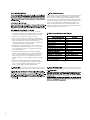
912L
The Titan 912L swing gate operator delivers the next generation of
easily installed, configured and maintained swing gate operators
from Nice. With a maximum gate capacity of 600 lbs and 20 ft,
this operator has a key lockable manual release, easily accessible
limit switch settings as well as simple in-the-field maintenance and
repair. The Titan gives dealers, installers and homeowners the
ability to take control of their access and security systems. This
operator includes a 2-year factory warranty against manufacturing
defects and lifetime customer support.
operator

2.2 - Gate latches
2.4 - Swing gates
and slide g control
point to
or
or slide
autono
periodic schedule.
2.5 - General requirements
countless
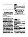
AUTOMATIC GATES ARE
NOT FOR PEDESTRIANS!
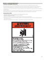
3 - SAFETY AND CAUTIONS
WARNING
IMPORTANT SAFETY INSTRUCTIONS
WARNING - TO REDUCE THE RISK OF INJURY OR DEATH READ AND
FOLLOW ALL INSTRUCTIONS.
3.1 - Properly installed safety devices
3.2 - Safety signs, notices to personnel warning signs
danger posed
t
lashing lamp that is
acti
te tim
2
This swing gate actuator is intended for those locations where vehicle traf-
(gate). The Titan 912L actuator is only to be used in conjunction with Nice
brand control boards. If the gate, actuator and control system are not fully
closed off from public access, the opening and closing of the gate system
may result in severe damage, injury or death.
In association with this gate actuator and this (these ) swing gate(s), at no
time should manual gate latches or locks be used. The forces applied to a
swing gate by the actuator could be in excess to those forces which are safe
for bystanders. Should unnecessary forces be applied to a gate system,
such as a manual lock or impediment, catastrophic failure of the gate,
actuator or control system could result in substantial damage, extensive
physical injury or death.
for vehicular traffic. They are powerful and
safety, security and longevity throughout the life of the system.
required for that specific installation. Care should always be used during
installation!
qualified service person make repairs to gate hardware.

main
them regu
application.
4.1 - Follow Instructions
4.2 - Intended usage
4.3 - Warnings, cautions and notes
can
can
incorporated in all installations.
tions.
and shoul
d
3.3 - Gate system safety devices
3.4 - Infrared beams and warning signs
3.5 - Establish the location
3.6 - Read and follow all instructions
3.7 - Keep children away
3.8 - Test the gate system
release.
3.9 - Keep gates properly maintained
i
technicians are not recommended.
4 - PRE-INSTALLATION NOTES
the application.
operator.
gate operation.
reach through gate
3
THIS ACTUATOR IS INTENDED FOR USE WITH VEHICULAR
SWING GATES ONLY, WHEN COMBINED WITH A NICE BRAND
CONTROL BOARD.
for these warnings, cautions and notes are intended to
an automatic gate system is installed.

4
4.3.53 All gate systems must utilize a monitored contact or non-contact
presence detection sensor.
4.3.55 Hardwired contact or non-contact sensors to signal the gate
actuator of entrapment conditions are recommended.

5
5 - INSTALLATION PROCEDURES
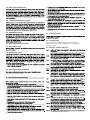
OVERHEAD VIEW
FIGURE 5 - 1 PULL TO OPEN INSTALLATION
FIGURE 5 - 2 VERTICAL PIVOT POSITION
VERTICAL POSITION OF PIVOT ARM
SIDE VIEW
The top edge of the Pivot Arm will be located 1/2”
below the center line for the gate bracket. The Pivot
Arm must be level when secured.
NOTE
If you have columns built around
your gate hinge post, check these
measurements for proper clearance
before proceeding with this pull to
open installation.
5.1 - Pivot Arm Installation
IMPORTANT
-
Never weld parts to the gate or posts when the operator circuit board is powered. Doing so may
damage the board beyond repair.
PULL TO OPEN INSTALLATION - PIVOT ARM INSTALLATION - Location of Pivot Point
The following instructions provide up to 105° of swing.
Measurements are taken from the center of pivot of the gate hinge.
The pivot arm needs to be securely mounted to the hinge post or equivalent mounting surface. It is recommended to weld
the pivot arm to a metal post. In order to achieve the correct articulation, geometry and rate of speed of the gate it is
critical that the measurements below are followed. The pivot arm may need to be cut to achieve the correct placement of
the actuator mounting hole. Measurements are taken from the center of pivot of the gate hinge.
Center line of
attachment point
for gate bracket
Hinge Post

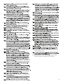
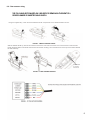
5.2 - Push to open installation
PIVOT ARM INSTALLATION - Location of Pivot Point
Measurements are taken from the center of pivot of the gate hinge.
The pivot arm needs to be securely mounted to the hinge post or equivalent mounting surface. It is recommended
to weld the pivot arm to a metal post. In order to achieve the correct articulation, geometry and rate of speed of the
gate it is critical that the measurements below are followed. The pivot arm may need to be cut to achieve the correct
placement of the actuator mounting hole. Measurements are taken from the center of pivot of the gate hinge.
DIRECTION OF OPENING
GATES CLOSED
HINGE POST HINGE POST
LEFT HAND SWING RIGHT HAND SWING
TOP VIEW
6”
11”
6”
11”
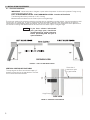
5.3 - Actuator mounting
Mount the actuator to the pivot arm as shown.
Please notice the washer goes below the actuator
The lock nut should be tight to prevent movement or
shifting when the actuator is running. This will also
prevent excessive “bounce” or “wobble” when the gate
stops moving.
FIGURE 5 - 3 PUSH TO OPEN INSTALLATION
FIGURE 5 - 4 ACTUATOR MOUNTING
6
FIGURE 5 - 5 GATE BRACKET MOUNTING

7
Manual Release In
Engaged Position
RUBBER
KEY
COVER
5.4 - Manual release/manual operation
1. Close handle
2. Rotate key 90° counterclock wise
and remove key.
3. Replace rubber key cover.
4. Operator is now in re-engaged in
Automatic Mode (manual
operation is not possible).
Manual Release Re-engage
FIGURE 5-7 MANUAL RELEASE RE-ENGAGE
1. Lift rubber key cover and insert
key into lock and rotate 90°
clockwise.
2. Lift handle
3. Actuator is now Disengaged
(manual operation is possible).
Manual Release Disengage
Manual Release in
Disengaged Position
90°
FIGURE 5-6 MANUAL RELEASE DISENGAGE

8
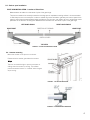
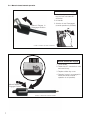
5.5 - Titan actuator wiring
Terminal Block
For Harness
Connections
With the release handle up, remove the screws from the limit cover and remove the cover. On the bottom of the actuator
loosen the strain relief nut and insert the wire into the actuator housing. The connections are on the top of the atuator behind
the limit assembly.
Using the supplied key, unlock the manual release handle. Lift upwards on the release handle as shown.
FIGURE 5 - 8 MANUAL RELEASE HANDLE
FIGURE 5 - 9 WIRE HARNESS INSERTION
THE FOLLOWING SECTION NEED ONLY BE USED FOR REWIRNG IN THE EVENT OF A
DESIRED LONGER OR SHORTER CABLE LENGTH.

9
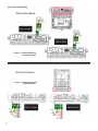
5.6 - Control board wiring
1050 Control Board
936 Control Board
FIGURE 5 - 11 WIRING DIAGRAM FOR
1050 CONTROL BOARD
FIGURE 5 - 12 WIRING DIAGRAM FOR
936 CONTOL BOARD

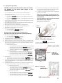
5.7 - Limit switch adjustment
10
1. From the manufacturer
, these units will be in the fully retracted position.
2. If the actuator is not mounted to the pivot arm, do so at this time, before
proceeding (see Sec. 5.3).
a. For a standard pull to open application, bring the gate leaf to the fully open
position.
b. For a reversed push to open application, bring the gate leaf to the fully closed
position.
3. Bring the bracket end of the actuator (with the gate bracket attached) into contact
with the gate and mark placement.
4. Remove the extension tube from the bracket and weld or bolt the bracket to the
gate using 3/8” bolts, lock washers and nuts.
5. Bolt the extension tube of the operator back into the gate bracket.
6. Disengage the actuator to allow for manual operation (see section 5.4).
7. Remove the top cover to expose the limit assembly.
8. Manually move the gate to the:
a. Fully closed position for pull to open applications
b. Fully open position for push to open applications
A clicking sound will be heard as this manual operation is
performed. This sound is the extend limit cog (blue) self-adjusting.
9. Manually move the gate back to the:
a. Fully open position for pull to open applications
b. Fully closed position for push to open applications
10. Re-engage the actuator to engage the drive train.
11. Plug the actuator into the control board (see Sec. 5.6).
12. Put the control board in hold-to-run (Learn) mode. (refer to control board manual)
13. Remove the plastic dual knob cover and turn the knob controlling the linear motion
of the retract limit cog (white) to bring it into contact with the limit switch. If this is
done correctly you will see:
a. With the 1050 control board
i. The LED below the motor connection port being used, illuminate green
indicating the open limit is active for a pull to open application.
ii. The LED below the motor connection port being used, illuminate red
indicating the closed limit is active for a push to open application.
b. With the 936 control board
i. The LED marked Limit 1 Open (or Limit 2 Open if using motor 2)
illuminate red indicating the open limit is active for a pull to open.
ii. The LED marked Limit 1 Close (or Limit 2 Close if using motor 2)
illuminate red indicating the close limit is active for a push to open.
14. Press and hold:
a. The close button until the close limit is activated for a pull to open application.
b. The open button until the open limit is activated for a push to open application.
15. If the location of the gate is not the location desired, disengage the actuator using
the manual release lever (sect 5.4), move the gate to the position desired and re-
engage the actuator.
16. Turn the knob controlling the linear motion of the extend limit cog (blue) to bring it
into contact with the limit switch. If this is done correctly you will see:
a. With the 1050 control board
i. The LED below the motor connection port being used, illuminate red
indicating the close limit is active for a pull to open application.
ii. The LED below the motor connection port being used, illuminate
green indicating the open limit is active for a push to open application.
b. With the 936 control board
i. The LED marked Limit 1 Close (or Limit 2 Close if using motor 2)
illuminate red indicating the Close limit is active for a pull to open.
ii. The LED marked Limit 1 Open (or Limit 2 Open if using motor 2)
illuminate red indicating the Open limit is active for a push to open.
FIGURE 5 - 13 LIMIT SWITCH ADJUSTMENT
Retract
adjustment
Extend
adjustment
Turning the knob in the direction shown above will move
the limit cog toward the limit switch
NOTE
18. If the location of the gate is not the location desired, engage
the manual release,move the gate to the position desired and
disengage the manual release, then repeat step 12.
19. Consult the control board manual for instruction regarding the
particular learn procedure.
Steps 9 thru 16 may need to be repeated if the open
and close positions established during the learn cycle
need adjustment.
*Once the operator has been learned and the location
of the limits is correct, replace the
dual knob cover and top cover.
FIGURE 5 - 14 LIMIT LED
LOCATION 1050
CONTROL BOARD
FIGURE 5 - 15 LIMIT LED
LOCATION 936
CONTROL BOARD
BEFORE continuing with this section, make sure to have
the MANUAL for the contol board specific to this
installation in hand.

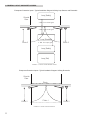
6- GENERAL LAYOUT AND SAFETY ACCESS
Entrapment Protection Inputs - Typical Installation Diagram Utilizing Loop Sensors and Photocells
Entrapment Protection Inputs - Typical Installation Diagram Utilizing Photocells
Loop (Safety)
Loop (Safety)
Loop (Shadow)
Loop (Exit)
4’ Min. from closed gate
4’ Min. from closed gate
4’ Min. from open gate
Photo 2 Photo 2
Outside
Gate
Outside
Gate
Photo
Photo 2 Photo 2
Photo 1
FIGURE 6 -1 LAYOUT FOR IN-GROUND LOOPS
FIGURE 6 -2 LAYOUT FOR PHOTOCELLS
1
1

SECTION 7 - ACCESSORIES AND SENSORS
EXTERNAL ENTRAPMENT PROTECTION
Non-contact and contact sensors must be installed individually or in combination with each other to provide external entrapment protection.
Care should be exercised to reduce the risk of nuisance tripping, such as when a vehicle trips the sensor while the gate is still moving, and one or more
contact sensors shall be located where the risk of entrapment or obstruction exists, such as the perimeter reachable by a moving gate or barrier.
A hardwired contact sensor shall be located and its wiring arranged so that the communication between the sensor and the gate operator is not subjected to
mechanical damage.
A wireless contact sensor such as one that transmits radio frequency (RF) signals to the gate operator for entrapment pr otection functions shall be located
where the transmission of the signals are not obstructed or impeded by building structures, natural landscaping or similar obstruction.
DURING INSTALLATION
• DISCONNECT POWER at the control panel before making any electric service power connection.
• Be aware of all moving parts and avoid close proximity to any pinch points.
• Know how to operate the manual release.
• Adjust the unit to use the minimum force required to operate the gate smoothly even during mid-travel reversing.
• Place controls a minimum of 8 feet away from the gate so that the user can see the gate and operate controls but cannot touch the gate or gate operator
while operating the controls.
• Warning signs must be placed on each side of the gate or in high-visibility areas to alert of automatic gate operations.
12

8- INSPECTION AND OPERATION
Proper inspection of all equipment is required to ensur e continuous
functionality, safety and to ensure reliable operation in all weather conditions.
Inspect electrical assemblies and wiring installations for damage, general
condition, and proper functioning to ensure the continued satisfactory
operation of the electrical system. Adjust, repair, overhaul, and test electrical
equipment and systems in accordance with the recommendations and
procedures in the gate operator system and/or component manufacturer’s
maintenance instructions.
Replace components of the electrical system that are damaged or defective
with identical parts, with manufacturer’s approved equipment, or its
equivalent to the original in operating characteristics, mechanical strength,
for and checks to be performed are listed below:
13
9 - EMERGENCY VEHICLE ACCESS
Contact us
Web: www.ApolloGateOpeners.com
Email: [email protected]
Phone: (800) 878-7829
Fax: (330) 650-9004
manually operated by engaging the manual release lever (see section 5.4).
-
 1
1
-
 2
2
-
 3
3
-
 4
4
-
 5
5
-
 6
6
-
 7
7
-
 8
8
-
 9
9
-
 10
10
-
 11
11
-
 12
12
-
 13
13
-
 14
14
-
 15
15
-
 16
16


Nice Apollo TITAN12Li Swing Gate Operator User manual
- Category
- Garage Door Opener
- Type
- User manual
- This manual is also suitable for
Ask a question and I''ll find the answer in the document
Finding information in a document is now easier with AI
Related papers
-
Nice Apollo 7300ETL-IL-1K Commercial Slide Gate Operator Installation guide
-
-
-
-
Nice Apollo CBOX936 Control Box Kit User manual
-
-
-
-
-
Other documents
-
Chamberlain LA400 Operating instructions
-
 Nice HySecurity SwingSmart CNX Swing Gate Operator Installation guide
-
Nice HySecurity SwingSmart CNX 20 User manual
-
 Nice HySecurity SlideSmart CNX Slide Gate Operator Installation guide
-
HySecurity CBOX Quick start guide
-
-
DKS 6003 Jan 2016 - July 2018 User manual
-
-
-
DoorKing 6006 User manual

