Si la lámpara viene con alambre a tierra. Conecter el
alambre a tierra de la lámpara al alambre a tierra de la caja
tomacorriente con un conector de alambres (no incluido)
espués de seguir los pasos anteriores. Nunca conectar el
alambra a tierra a los alambres eléctros negro o blanco.
18) Haga les conexiones de los alambres (no se proveen los
connectores.) La tabla de referencia de abajo indica las
conexiones correctas y los alambres correspondientes.
19) Levante el escudete hasta el cielorraso.
20) Asegure en el escudete en el lugar apretando el anillo
roscado en el ojal de collar roscado.
21) Baje el vidrio sobre el casquillo. Coloque la parte inferior del
vidrio en la taza casquillo.
1) Jale el alambre del artefacto a través del vástago del centro.
Rosque el extremo inferior del vástago del centro dentro del
acoplamiento en la parte superior del cuerpo del artefacto.
2) Pase el alambre del artefacto a través del agujero en la
sección inferior de la esfera. Coloque la sección inferior de
la esfera en la parte superior del vástago del centro.
3) Descienda el adorno en espiral lateral hacia el brazo del
artefacto. Pase el agujero en la parte inferior del adorno en
espiral sobre el espárrago roscado en la parte superior del
brazo.
4) Rosque la perilla redonda sobre el espárrago roscado.
NOTA: No apriete completamente la perilla redonda. Esto se
hará cuando todos los adornos en espiral laterales estén
ensamblados a los brazos.
5) Alinee el agujero en la parte superior del adorno en espiral
lateral con el agujero en el lado de la sección inferior de la
esfera. Rosque el espárrago de cabeza redonda dentro del
agujero en el adorno en espiral y dentro de la esfera. NOTA:
No apriete completamente el espárrago de cabeza esférica.
Esto se hará cuando todos los adornos en espiral laterales
estén ensamblados a los brazos.
6) Repita los pasos 3 – 5 para los adornos en espiral laterales
restantes.
7) Cuando todos los adornos en espiral laterales estén
ensamblados apriete completamente las perillas redondas y
los espárragos de cabeza esférica.
8) Jale el alambre a través del tubo roscado en el ensamblaje
del lazo superior. Atornille el tubo roscado en el ensamblaje
del lazo superior dentro del agujero en el centro de la
sección inferior de la esfera.
9) APAGUE LA ALIMENTACIÓN ELÉCTRICA.
IMPORTANTE: Antes de comenzar, NUNCA trate de trabajar
sin antes desconectar la corriente hasta que el trabajo se
termine.
a) Vaya a la caja principal de fusibles, o interruptor o caja
de circuitos de su casa. Coloque el interruptor de la
corriente principal en posición de apagado “OFF”.
b) Desatornille el (los) fusible (s), o coloque el interruptor o
interruptores del breaker en posición de apagado
“OFF”, que controla (n) la corriente hacia el artefacto o
habitación donde está trabajando.
c) Coloque el interruptor de pared en posición de apagado
“OFF”. Si el artefacto que se va a reemplazar tiene un
interruptor o cadena que se jala, colóquelos en la
posición de apagado “OFF”.
10) Seque el tubo roscado de la bolsa de piezas y atornille en el
ojal de collar roscado un minimo de 6 mm (1/4”). Inmovilice
en el lugar con la tuerca hexagonal.
11) Instale otra tuerca hexagonal en el tubo roscado casi
tocando la primera tuerca hexagonal. Ahora, atornille el tubo
roscado en la abrazadera de montaje. La abrazadera de
montaje se debe colocar con la rosca extruida mirando
hacia la caja de salida. El tubo roscado debe sobresalir
atrás de la abrazadera de montaje. Atornille la tercera tuerca
hexagonal en el extremo del tubo roscado que sobresale de
la parte posterior de la abrazadera de montaje.
12) Conecte la abrazadera de montaje a la caja de salida.
13) Destornille el anillo roscado del ojal de collar roscado deben
sobresalir aproximadamente la mitad. Ajuste el ojal del
collar roscado girando el conjunto hacia arriba a abajo, en la
abrazadera de montaje. Retire el escudete.
14) Después que encuentre la posición deseada, apriete la
tuerca hexagonal superior contra el fondo de la abrazadera
de montaje.
15) Después de encontrar la posición deseada, apriete ambas
tuercas hexagonales, la superior y la inferior, arriba contra
las partes superior e inferior de la abrazadera de montaje.
16) Pase el alambre eléctrico y el alambre de tierra a través de
los estabones de la cadena, a espacios maximos de 3
pulgadas. Pase el alambre a través del anillo roscado, el
escudete, el ojal de collar roscado, el tubo roscado y dentro
de la caja de salida.
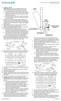
17) Instrucciones de conexión a tierra solamente para los
Estados Unidos. (Vea la ilustracion A o B).
A) En las lámparas que tienen el fleje, de montaje con un
agujero y dos hoyuelos realzados. Enrollar el alambre a
tierra de la caja tomacorriente alrededor del tornillo
verde y pasarlo por el aquiero.
B) En las lámparas con una arandela acopada. Fijar el
alambre a tierra de la caja tomacorriente del ajo de la
arandela acoada y tornillo verde, y paser por el fleje de
montaje.
Date Issued: 2/28/14 IS-43506-US
ARANDELA
CONCAVA
A
B
TIERRA DE LA
CAJA DE SALIDA
TORNILLO DE TIERRA,
VERDE
DEPRESIONES
TIERRA
ARTEFACTO
CONECTOR DE ALAMBRE
(NO SE PROVEE)
TIERRA DE LA
CAJA DE SALIDA
TORNILLO DE TIERRA,
VERDE
TIERRA
ARTEFACTO
Conectar el alambre de
suministro negro o rojo al
Conectar el alambre de
suministro blanco al
Negro Blanco
*Cordon paralelo (redondo y liso)
*Cordon paralelo (cuadrado y estriado)
Claro, marrón, amarillio o negro
sin hebra identificadora
Claro, marrón, amarillio o negro
con hebra identificadora
Alambre aislado (diferente del verde)
con conductor de cobre
Alambre aislado (diferente del
verde) con conductor de plata
*Nota: Cuando se utiliza alambre paralelo
(SPT I y SPT II). El alambre neutro es de forma
cuadrada o estriada y el otro alambre será de
forma redonda o lisa. (Vea la ilustracíón).
Hilo Neutral
SEE OTHER SIDE FOR ENGLISH TRANSLATIONS.
VEA EL OTRO LADO DE TRADUCCIONES AL INGLÉS.
We’re here to help 866-558-5706
Hrs: M-F 9am to 5pm EST
MOUNTING STRAP
ABRAZADERA DE MONTAJE
HEXNUT
TUERCA HEXAGONAL
THREADED PIPE
TUBO ROSCADO
CANOPY
ESCUDETE
THREADED RING
ANILLO ROSCADO
SCREW COLLAR LOOP
OJAL DE COLLAR
ROSCADO
FIXTURE BODY
CUERPO DEL ARTEFACTO
ARM
BRAZO
LOOP ASSEMBLY
ENSAMBLAJE DEL LAZO
CENTER STEM
VÁSTAGO DEL CENTRO
BALL
KNOB
PERILLA
REDONDA
BALL STUD
ESPÁRRAGO DE
CABEZA REDONDA
SPHERE
ESFERA
GLASS
VIDRIO
THREADED STUD
ESPÁRRAGO ROSCADO
SIDE SCROLL
ES;IRAL LATERAL