Sterling SP2275A-38S Installation guide

Type
Installation guide

This manual is also suitable for

Front
Edge
Level
Wall Jamb
Pencil
x2
Front
Edge
Wall Jamb
Expander Jamb
x2
Front
Edge
Screws
#8-18 x
1-3/4"
x2
Front Edge
Silicone Sealant
5/16" Drill
Bit
x2
3
1
2
Expander
Jamb
Adjustment Block
Wall Jamb
1/2"
(13 mm)
Tape
Screw
x4
Screw
#8 x 3-1/2"
Tin Snips
Masking Tape100% Silicone Sealant
Assorted Drill Bits
Hardware Pack
1080993**
1088417
Bushing
1088416
Pivot Pin
(Deep Bronze)
682040
(Matte Silver)
682039
Column
(Nickel)
(Brass)
(Silver)
682001
682011
682038
(Matte Silver)
(Nickel)
(Deep Bronze)
681546
(Silver)
681501
(Brass)
681511
681544
681545
Wall Jamb
1031813
Adjustment Block
Series
Number Label
(Matte Silver)
(Nickel)
(Deep Bronze)
919934
(Silver)
919918
(Brass)
919919
919932
919933
Bridge Member (Includes Seal 521307)
(Black)1049018-T
(Silver)
(Brass)
1049018-D
1049018-L
Screw
Door Panel*
(Includes Magnet 681301)
Side Panel*
Side Panel*
1031659-C
Screw
1031659-C
Screw
1077762
Anchor
1048208-A
Screw
1088418
Plug
1088771
Panel Cushion
681301
Magnet
681200
Magnet
521311
Seal
521307
Seal
521307
Seal
1052892-A
Washer
1088417
Bushing
1088416
Pivot Pin
(Matte Silver)
684131
Strike Post (Includes Magnet 681200)
(Nickel)
(Brass)
(Deep Bronze)
684132
(Silver)
684101
684110
684130
(Matte Silver)
684031
Flange (Includes Seal 521311)
(Nickel)
(Brass)
(Deep Bronze)
684032
(Deep Bronze)
682040
(Silver)
684001
684010
684030
(Matte Silver)
682039
Column
(Nickel)
(Brass)
(Silver)
682001
682011
682038
(Matte Silver)
(Nickel)
(Deep Bronze)
681546
(Silver)
681501
(Brass)
681511
681544
681545
Wall Jamb
(Black)1049018-S
(Silver)
(Brass)
1049018-J
1049018-K
Screw
Front
Edge
Front
Edge
3/4"
(19 mm)
3/4"
(19 mm)
Mark the location of the wall jambs. The front
edge should be 3/4” (19 mm) from the front edge
of the threshold.
Move the wall jambs into place and check the fit.
When needed, snip and file the bottom edges of
the wall jambs for a snug fit.
Align the front edge of the wall jambs with the
marks. Plumb the wall jambs. Mark the front
edges of the wall jambs and the wall jamb holes.
Remove the wall jambs. Drill 5/16” holes at each
mark and insert an anchor in each hole.
Slide an adjustment block onto each end of the
wall jambs, positioned over the first hole. Secure
in place with tape. Loosen the adjustment in each
adjustment block until it extends 1/2” (13 mm).
Apply a bead of silicone sealant to the groove
along the entire wall jamb.
Move a wall jamb into place with the sealant
groove against the wall, toward the outside of
the shower. Secure with three screws. Repeat for
other side.
Carefully lift the side panels onto the shower
ledge. Align the expander jamb on the panel with
the wall jamb.
Use a screwdriver to tighten or loosen the
adjustment blocks until they firmly and evenly
contact the wall frame.
Secure the wall panels in place with two screws.
SP2270 Series Neo-Angle Shower Doors
IMPORTANT! Do not cut the top track the same length as the bottom track.
Walls must be within 3/8” (10 mm) of plumb.
Cover the drain with tape to avoid loss of small parts.
Follow the silicone sealant manufacturer’s instructions for application and
curing time.
To watch this installation online; visit the product page at
www.sterlingplumbing.com.
For care and cleaning and other information; visit
www.sterlingplumbing.com/care-and-cleaning.
11187937-2-C
USA/Canada: 1-800-STERLING (1-800-783-7546)
México: 001-877-680-1310
1187937-2-C
Installation and Care Instructions
*Call Customer Care Center to order replacement parts.
**Finish/color code must be specifi ed when ordering.
Retain this document for future servicing.
Record model number from box for reference.
Model Number:______________
Required Tools Parts Identifi cation
2 3 4
7 86 9
1 5
10
WARNING: Risk of serious injury. Damage prior to installation can
result in glass shattering. Inspect the glass and all parts for damage
before installation.
WARNING: Risk of serious injury. Improper installation can result
in glass shattering. Follow all installation instructions.
WARNING: Risk of serious injury. Do not cut tempered glass.
Tempered glass will shatter if cut.
WARNING: Risk of serious injury. Shower door and side panels
can shatter. Regularly inspect the glass and all parts for damage,
missing, or loose parts.
WARNING: Risk of serious injury. Always wear safety glasses
while cutting and drilling.
NOTICE: Do not touch the edges of the tempered glass with tools or any
other hard objects. Do not set the unframed tempered glass directly on the
floor or any hard surface.
IMPORTANT! Leave this manual for the end user.
Read these instructions before installing or using this product.
SterlingPlumbing.com
1/4" (6 mm) Longer
Seal
1-1/4"
(32 mm)
Seal
Bridge Member
1-1/4"
(32 mm)
Flange
Flange
Strike Post
Front
Bridge Member
#8 x 1"
Magnet
Seal
Strike Post
Bridge Member
Front View
Flush Alignment
Flange
Bridge Member
100˚
100˚
Pivot
Side
Right PivotLeft Pivot
18-7/8"
(479 mm)
Pivot
Side
#8 x 5/8"
Groove
and
Flange
Groove
and
Flange
Bushing
Bushing
Plug
Plug
Plug
Seal here.
Seal here.
Pivot Side Strike Side
Bottom
Pivot Pin
Bushing
Nylon
Washer
Pivot Hole
Top Pivot Pin
Bushing
Seal here, outside only.
100% Silicone Sealant
Seal
Seal here.
Troubleshooting
Installation Recommended Action
1. The door does not fit. A. Confirm the correct receptor is installed.
2. The frame and/or door are not aligned and
plumb.
A. Perform the adjustment procedure in Steps 20 and 21.
3. The seal is deformed. A. Soak the seal in hot water. The seal will regain its shape.
Operation Recommended Action
1. There is leaking at the bottom of the door
frame.
A. Tighten the crossmembers and reseal.
2. There is leaking from the door area. A. Confirm the correct areas are sealed per Steps 18, 22, and 23. Reverse the pivot side of the door.
3. The door contacts the base when opened or
closed.
A. Remove the door and insert a second nylon washer on the bottom pivot pin. See Step 17.
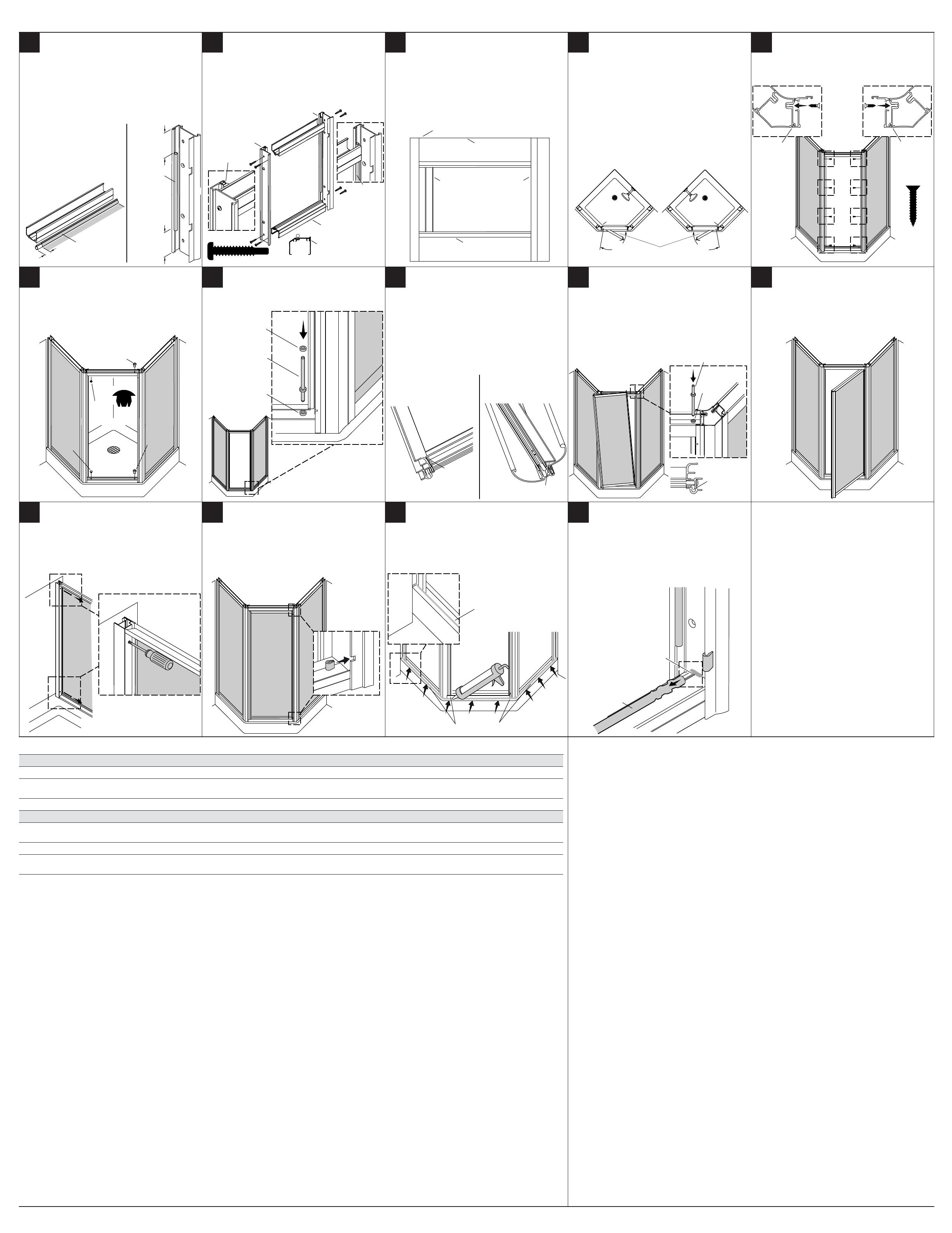
Cut the seal 1/4” (6 mm) longer than the bridge
member. Cut the final 1-1/4” (32 mm) of the seal
off each end of the flange.
On a work surface assemble the flange and strike
post to the bridge members with eight screws.
The flange should be on the pivot side of the
frame.
Confirm that the bridge members are flush with
the flange and the strike post. To adjust loosen
the screws and move the bridge member up or
down.
Determine right or left pivot side. Confirm there
are no obstructions in the door path. Illustrations
show right pivot throughout. Reverse for left side
pivot installations.
Make sure the grooves and flanges are engaged.
Secure with four screws on each side.
Insert two plugs on the magnet side and two
bushings on the pivot side.
Install the pivot pin and nylon washer. Seal the bottom of the door panel frame with
silicone sealant.
Lift the door panel, align the bottom pivot hole
and pin, and lower into place. Align the top pivot
hole and top bushing. Insert the long end of the
pivot pin from above.
Confirm the door is square to the framework.
Check for smooth operation. Adjust as needed.
To adjust, remove the screws and turn the
adjustment block screws until aligned. Reinstall
the screws.
Install a cushion into the two flange slots and
snap into place.
Outside the shower, apply 100% silicone sealant
to the entire shower door length along the
bottom.
Slide the seal back and apply a bead of silicone
sealant at each side of the door opening. Allow
the silicone sealant to cure 24 hours before using.
21187937-2-C ©2014 Kohler Co.
11 12
17
22
13
18
23
16
21
14
19
24
15
20
STERLING® Warranty – Bath and Shower Doors
5-Years Limited
SP2375 5100 Series 5300 Series 5400 Series 6300 Series 6500 Series
3-Years Limited
1500 Series 1900 Series 2200 Series 4600 Series 4700 Series 4800 Series 4900 Series 5900 Series
1-Year Limited
500 Series 600 Series 660 Series 670 Series 690 Series 950 Series 2300 Series 3100 Series
Based on the classification specified above, STERLING bath and shower doors are warranted to be free of
manufacturing defects within the time of the specified model’s limited warranty from date of sale.
Kohler Co. will, at its election, repair, rectify or replace a fixture when inspection by Kohler Co. discloses any such
defects occurring in normal usage within the time period of coverage stated above. Kohler Co. is not responsible
for removal or installation costs where replacement is indicated. Damages due to improper handling, installation or
maintenance are not considered manufacturing defects and are not covered by this warranty. This warranty is valid
for the original, consumer purchaser only.
To obtain warranty service, contact Sterling, either through your plumbing contractor, home center, wholesaler or
dealer, or by calling or writing Sterling, Consumer Services, 444 Highland Drive, Kohler, Wisconsin 53044, 1-800-
783-7546.
TO THE EXTENT PERMITTED BY LAW, ALL IMPLIED WARRANTIES INCLUDING THOSE OF
MERCHANTABILITY AND FITNESS FOR A PARTICULAR PURPOSE ARE HEREBY DISCLAIMED.
KOHLER CO. AND SELLER HEREBY DISCLAIM ANY LIABILITY FOR SPECIAL, INCIDENTAL, OR
CONSEQUENTIAL DAMAGES. Some states/provinces do not allow limitations on how long an implied warranty
lasts, or the exclusion or limitation of special, incidental or consequential damages, so these limitations and
exclusions may not apply to you. This warranty gives you specific legal rights. You may have other rights which
vary from state/province to state/province.
This is the exclusive written warranty for Kohler Co.
  • Page 1 1
  • Page 2 2
  • Page 3 3
  • Page 4 4
  • Page 5 5
  • Page 6 6

Sterling SP2275A-38S Installation guide

Type
Installation guide
This manual is also suitable for

Ask a question and I''ll find the answer in the document

Finding information in a document is now easier with AI