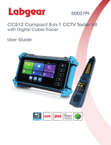
Security Tronix ST-ALLIN1-TEST2 Owner's manual

Category
Cable network testers
Type
Owner's manual
ST-ALLIN1-TEST2
USER MANUAL
www.securitytronix.comwww.nacebrands.com
Thank you for purchasing the SecurityTronix ST-ALLIN1-TEST2 CVI/TVI/AHD/SDI, Analog
and IP camera test monitor with network tester.
To use the ST-ALLIN1-TEST2 safely, please read the Safety Information carefully.
The manual should be kept with the ST-ALLIN1-TEST2 for reference.
Keep the S/N label for after-sale service within the warranty period. Please see the last page of the
manual for warranty information.
If you have any questions or problems while using the ST-ALLIN1-TEST2 camera tester, please
contact Securitytronix technical support department at (610) 429-0334
Visit our website http://www.securitytronix.com for additional information and up to date user
manuals.
DISCLAIMER: All applications and features of the ST-ALLIN1-TEST2 are intended for
use on your own networking equipment or with the written permission from the owner of
the equipment you are connecting to. You may not use the ST-ALLIN1-TEST2 to access
any IP cameras or any other networking equipment that you are not authorized to access.
This is illegal. Always check with your local, state and federal laws before using the
ST-ALLIN1-TEST2. SecurityTronix does not assume any liability for loss of data or
connecting to an unauthorized network device.
WARNING:
THIS PRODUCT CAN EXPOSE YOU TO POLYBROMINATED
BIPHENYLS, WHICH IS KNOWN TO THE STATE OF CALIFORNIA TO CAUSE
CANCER AND BIRTH DEFECTS OR OTHER REPRODUCTIVE HARM. FOR MORE
INFORMATION GO TO WWW.PROP65WARNINGA.CA.GOV
Table Of Contents
1 .Safety information ----------------------------------------------------------------------------------------------------- 1
2. IP Camera Tester Introduction --------------------------------------------------------------------------------------- 2
2.1 General ----------------------------------------------------------------------------------------------------------- 2
2.2 Packing list ------------------------------------------------------------------------------------------------------ 2
2.3 Function interface ---------------------------------------------------------------------------------------------- 3
3. Operation ---------------------------------------------------------------------------------------------------------------- 6
3.1 Installing the Battery ------------------------------------------------------------------------------------------- 6
3.2 Instrument connection ----------------------------------------------------------------------------------------- 7
3.2.1 IP camera connection ---------------------------------------------------------------------------------------- 7
3.2.2 Analog camera connection --------------------------------------------------------------------------------- 8
3.2.3 HD Coaxial camera connection --------------------------------------------------------------------- 9
3.2.4 HDMI IN --------------------------------------------------------------------------------------------- 10
3.3 OSD menu ----------------------------------------------------------------------------------------------------- 10
3.3.1 Lite mode& Normal mode ------------------------------------------------------------------------- 11
3.3.2 Drop-down Menu ------------------------------------------------------------------------------------ 14
3.3.3 Short cut-menu --------------------------------------------------------------------------------------- 15
3.3.4 Screen capture ---------------------------------------------------------------------------------------- 16
3.3.5 TesterPlay (Output an RTSP stream) ------------------------------------------------------------- 16
3.3.6 Rapid video ------------------------------------------------------------------------------------------- 17
3.3.7 IP discovery ------------------------------------------------------------------------------------------- 18
3.3.8 ONVIF test -------------------------------------------------------------------------------------------- 19
3.3.9 IP camera test ----------------------------------------------------------------------------------------- 32
3.3.10 HDMI IN --------------------------------------------------------------------------------------------- 35
3.3.11 CVBS (Composite Video Blanking & Sync)------------------------------------------------- 37
3.3.12 Color-bar generator (TV OUT) ------------------------------------------------------------------ 42
3.3.13 SDI Camera Test ----------------------------------------------------------------------------------- 43
3.3.14 CVI camera test ------------------------------------------------------------------------------------- 44
3.3.15 TVI camera test ------------------------------------------------------------------------------------- 46
3.3.16 AHD camera test ----------------------------------------------------------------------------------- 47
3.3.17 Network tool ---------------------------------------------------------------------------------------- 49
1IP address scan -------------------------------------------------------------------------------------- 49
2PING Test -------------------------------------------------------------------------------------------- 49
3Network test (Ethernet bandwidth test) --------------------------------------------------------- 50
4Port Flashing ----------------------------------------------------------------------------------------- 52
5DHCP server ----------------------------------------------------------------------------------------- 53
6Trace route ------------------------------------------------------------------------------------------- 54
7Link monitor ----------------------------------------------------------------------------------------- 55
3.3.18 Rapid IP Discovery -------------------------------------------------------------------------------- 55
3.3.19 PoE power / DC12V 2A and DC 5V 2A USB power output ------------------------------- 56
3.3.20 Cable Test ------------------------------------------------------------------------------------------ 57
3.3.21 RJ45 cable TDR test ------------------------------------------------------------------------------- 58
3.3.22 Cable Tracer ----------------------------------------------------------------------------------------- 61
3.3.24 PoE Voltage test ------------------------------------------------------------------------------------ 62
3.3.25 12V power input test ------------------------------------------------------------------------------- 63
3.3.26 Digital Multi-meter -------------------------------------------------------------------------------- 64
3.3.29 Audio Record --------------------------------------------------------------------------------------- 71
3.3.30 Data monitor ---------------------------------------------------------------------------------------- 72
3.3.31 Audio player ----------------------------------------------------------------------------------------- 72
3.3.32 Media Player ---------------------------------------------------------------------------------------- 73
3.3.33 RTSP Player ----------------------------------------------------------------------------------------- 74
3.3.34 Hik test tool------------------------------------------------------------------------------------------ 75
3.3.35 Dahua test tool -------------------------------------------------------------------------------------- 77
3.3.36 Update ------------------------------------------------------------------------------------------------ 80
3.3.37 Office ------------------------------------------------------------------------------------------------- 81
3.3.38 LED Flashlight -------------------------------------------------------------------------------------- 81
3.3.39 Browser ---------------------------------------------------------------------------------------------- 82
3.3.40 Notepad ---------------------------------------------------------------------------------------------- 83
3.3.41 System Setting -------------------------------------------------------------------------------------- 83
3.3.42 File explorer ----------------------------------------------------------------------------------------- 87
3.3.43 Theme ------------------------------------------------------------------------------------------------ 89
3. 4 Audio test ----------------------------------------------------------------------------------------------------- 91
3.5 HDMI output -------------------------------------------------------------------------------------------------- 92
3.6 PoE power output --------------------------------------------------------------------------------------------- 92
3.7 DC12V 2A power output ----------------------------------------------------------------------------------- 93
4. Specifications --------------------------------------------------------------------------------------------------------- 94
4.1 General Specifications --------------------------------------------------------------------------------------- 94
4.2 Multi-meter specifications ---------------------------------------------------------------------------------- 97
Page.1.
1 .Safety information
The ST-ALLIN1-TEST2 is intended for use in compliance with applicable codes and laws.
Do not expose to moisture.
Do not drop.
The tester should not be charged over 8 hours.
The tester should not be used in an environment with any flammable gasses or chemicals.
Do not disassemble the ST-ALLIN1-TEST2 meter except to change the battery.
Do not use any chemical cleaning products to clean the test meter. Use a dry cloth.
Do not use during an electrical storm.
Digital Multi-meter safety
Prior to taking any measurements, be sure you are using the correct range, function and input jack.
Red is positive, black is negative.
Never exceed the protection limit values for each range of measurement.
While measuring a live circuit, do NOT touch any unused terminals.
If the value to be measured is unknown while using the manual range, set the range selector to the
highest position.
Always be careful when working with AC or DC voltages to avoid injury or death. Keep your fingers
behind the probe barriers while measuring. Do NOT touch the metal probes while taking any
measurements.
Never perform any capacitance measurements unless the capacitor has been fully discharged.
Page.2.
2. ST-ALLIN-TEST2 Introduction
2.1 General
The ST-ALLIN1-TEST2 is designed for maintenance and installation of IP cameras, analog cameras,
TVI, CVI, AHD, SDI/EX-SDI cameras, as well as testing 4K H.264 /4K H.265 cameras via mainstream.
The 1280x800 resolution enables it to display network HD cameras and analog cameras in high
resolution. The unit supports many ONVIF PTZ and analog PTZ controls.
This tester is also a great tool for Ethernet network testing. It can test PoE power voltage, PING, and
perform IP address searching. The separate blue cable tracer can be used to locate individual connected
cables from a bundle of cables, and test LAN cables for proper connection termination. Other functions
include providing 24W PoE power to your IP camera, HDMI IN and OUT, CVBS loop test, LED
Flashlight, 12V DC 2A power output, and much more. Its portability, user-friendly design, and many
other functions make the ST-ALLIN1-TEST2 an essential tool for all installers and technicians.
2.2 Packing list
1) ST-ALLIN1-TEST2
2) 12VDC 2A power adapter
3) Network cable tester
4) Polymer lithium ion battery (7.4V DC 5400mAh)
5) BNC cable
6) Multi-meter test leads one pair of red and black
7) 12V DC Output Power cable
8) 3.5mm Audio cable
9) Safety lanyard
10) Tool bag
11) Manual
12) 8GB SD card
Page.3.
2.3 Function interface
Page.4.
1
Press for more than 2 seconds to turn the unit on or off. Quick press to put the
display into sleep mode.
2
Press to call the menu.
3
Press for up to 4x digital zoom.
4
Far focus: Adjust the focus for a “far” field of view.
5
Near focus: Adjust the focus for a “near” field of view.
6
TELE: zoom in the image.
7
WIDE: zoom out the image.
8
Confirm the setting of a parameter, open or enlarge the aperture.
9
Return or cancel while setting a parameter in the menu, close or decrease the
aperture.
10
Upward, set function or add parameter. Tilt PTZ camera upward.
11
Rightward, select the parameter whose value will be changed. Add the value of the
parameter. Pan PTZ camera right.
12
Downward, set function or reduce the value of the parameter. Tilt PTZ cameras
downward.
13
Leftward, select the parameter whose value will be changed. Pan PTZ cameras left.
14
Confirm key, (Long press to take a screen shot).
15
Return/Close: Return or cancel while setting a parameter in the menu, close or
decrease the aperture.
17
Charge indicator. Lights red while the battery is being charged. Once charging is
complete, the indicator turns off automatically.
18
RS485 data transmission indicator. Lights red while data is being transmitted.
19
Data received indicator. Lights red while the data is being received.
20
Power indicator. Lights green while the tester is powered on by the adapter.
Page.5.
Top interface
Bottom interface
21
12VDC 2A power output
22
HDMI IN
23
CVBS IN/AHD /TVI/CVI Coaxial interface
24
Video signal outputBNC interface/ cable tracer interface
25
LED lamp
26
RS485 Interface: RS485communication for PTZ
27
SDI input (BNC interface)
28
HDMI output interface
29
Micro SD card, (comes with 8GB card, supports up to 32GB)
30
UTP cable port: UTP cable tester port/ Cable tracer port
31
PSE power sourcing equipment. Tests PoE voltage.
Page.6.
32
PoE power supply output or LAN test port (Use to test PoE or non-PoE IP camera)
33
Audio output and earphone interface
34
Audio input
35
USB 5V 2A power output (used only for power, not data)
36
12VDC 2A charging interface
37
12VDC 2A power output, for DC power output
3. Operation
3.1 Installing the Battery
The ST-ALLIN1-TEST2 includes a lithium ion polymer rechargeable battery. Please remove and
retain the plastic tab that disconnects the battery pack from the tester. Re-install this tab when
transporting the unit or for long term storage.
You do not need to disconnect the battery during normal use
Pressing the key continuously can power on or off the tester.
Notice: Please use the original battery and charger for the tester.
When the battery icon is full or the charge indicator turns off automatically, this indicates
battery charging is complete.
Notice: When the Charge Indicator turns off, the battery is approximately 90% charged.
Charging time can be extended for about 1 hour without damaging the battery.
Notice: Press the key for several seconds to force the unit to restart in the event of an
abnormal operation.
Notice: the red and black multi-meter leads must be inserted into the correct ports.
Page.7.
Warning: Instrument communication port voltage must not exceed 6V as exceeding this may
damage the tester.
Warning: DO NOT insert multi-meter leads in the
Current terminals to measure voltage.
3.2 Instrument connection
3.2.1 IP camera connection (not using built in PoE)
Power an IP camera with an independent power supply, then connect the IP camera to the
ST-ALLIN1-TEST2 LAN port. If the link indicator of the LAN port is green and the data indicator
flickers, it means the IP camera and the ST-ALLIN1-TEST2 are communicating. If the two indicators
don’t flicker, check if the IP camera is powered on and the network cable is functioning properly.
Note: 1) If the IP camera requires PoE power, connect the IP camera to the LAN port, then click
on the POE Power Output app. Click on the POE power icon to turn PoE Power on or off. Note: the
camera will not respond immediately, as it needs time to fully boot up before transmitting a signal.
2) If using the ST-ALLIN1-TEST2 to test PoE voltage, please make sure the DC power out
is turned off. Connect the IPC to the LAN port, and the PSE IN port to the PoE switch being tested. In
Page.8.
this configuration, the IPC will be powered by the POE switch, and NOT the ST-ALLIN1-TEST2. Do
NOT activate DC power with a PoE switch connected to the LAN port.
Warning: PoE switch or PSE (power sourcing equipment) can only be connected to “PSE IN”
port, otherwise this will damage the unit.
3.2.2 Analog camera connection
(1)) Connect the camera's video output to the VIDEO IN port. The image will display once the camera
is powered on, and the PTZ app is opened.
(2) ST-ALLIN1-TEST2 “VIDEO OUT” interface connects to the video input of a separate monitor (if
required).
(3) If applicable, connect the camera or the PTZ dome’s RS485 controller cable to the tester’s RS485
interface. (Note: ensure that RS485 cable polarities are not reversed)
Page.9.
3.2.3 High Definition over Coax camera connection
SDI, CVI, TVI, and AHD cameras are classified as HDoC (High Definition over Coax) cameras. The
following instruction on how to connect a HDoC camera to the tester applies to CVI, TVI, SDI, and
AHD cameras.
(1) Connect the HDoC camera's video output to the appropriate “AHD CVI TVI” or “HD-SDI EX-SDI”
interface on the top of the tester. The image will display on the screen once the camera is powered, and
the appropriate TVI/CVI/AHD/SDI app is opened.
(2) If applicable, and the camera does not support CoC (Control over Coax), connect the camera or the
PTZ dome’s RS485 controller cable to the tester’s RS485 interface. (Note: ensure that RS485 cable
polarities are not reversed)
Page.10.
3.2.4 HDMI IN
You can connect a DVR or other HDMI source to the ST-ALLIN1-TEST2 meter to use a portable
HDMI monitor. The image will display once the device is connected, powered, and the HDMI In app is
opened.
3.3 OSD menu
Press the key 2 seconds to turn on.
Press the key again to turn off.
Short press the key to enter sleep mode, press it again to resume.
If the tester behaves abnormally and cannot be turned off, Press the key for several seconds to
force a restart.
Page.11.
3.3.1 Lite mode& Normal mode
Lite mode: A different GUI style that makes the apps organized into groups.
In Lite mode, Press the icons several seconds to drag and drop them to other folders.
In Lite mode, click the hand icon in the lower right corner to release the icon lock and
re-organize the apps within that folder to your liking.
Page.12.
Normal mode
Tap the screen and slide left or right to change menus.
In normal mode, press the icon for several seconds to enter management mode. You can change the
icon locations as well as move them to the quick access tool bar below.
You can move the icons to any page or create new pages. This functionality allows you to best
customize the interface to your needs.
Page.13.
Create New Folder: Drag an icon to the folder in the top right corner and enter a folder name. The Icon
will be placed in the newly named folder.
Press the folder several seconds to change the folder name or to move the icons out of a folder. The
folder will be deleted automatically if no icons are inside it.
Select Icons to move. If done, click
Page.14.
3.3.2 Drop-down Menu
Press and slide down at the top-right corner to open the drop-down menu. The drop-down menu
includes POE power output, IP settings, HDMI IN, CVBS, LAN, settings etc.
HDMI: Click HDMI to enter the HDMI IN mode to display an input from a HDMI source. You
can dual test IP & HDMI or Analog & HDMI at the same time.
CVBS: Click the “CVBS” icon to enter the CVBS testing mode.
TV OUT: Click TV OUT to open a floating window featuring the color bar generator. When
you connect a video source over BNC, it will display in this window.
LAN: Display network port or WIFI connection real-time statistics. This will show download
speeds and other network parameters.
Settings: Enter settings menu.
IP: Enter IP Settings menu.
Power Output: Quickly turn on or off PoE power output.
Page.15.
3.3.3 Short cut-menu
You can call the shortcut menu by pressing the physical button.
Press the “ button to turn it on or off or switch functions, then press or the app name
to enter the selected app, or press outside the pop up menu to exit.
You can manually select any application in the app list to be included in the shortcut menu. Long press
the icon in the “All application” list to move it to the Shortcut menu. Long pressing the icon in the
“Shortcut menu” will remove it from that list.
  • Page 1 1
  • Page 2 2
  • Page 3 3
  • Page 4 4
  • Page 5 5
  • Page 6 6
  • Page 7 7
  • Page 8 8
  • Page 9 9
  • Page 10 10
  • Page 11 11
  • Page 12 12
  • Page 13 13
  • Page 14 14
  • Page 15 15
  • Page 16 16
  • Page 17 17
  • Page 18 18
  • Page 19 19
  • Page 20 20
  • Page 21 21
  • Page 22 22
  • Page 23 23
  • Page 24 24
  • Page 25 25
  • Page 26 26
  • Page 27 27
  • Page 28 28
  • Page 29 29
  • Page 30 30
  • Page 31 31
  • Page 32 32
  • Page 33 33
  • Page 34 34
  • Page 35 35
  • Page 36 36
  • Page 37 37
  • Page 38 38
  • Page 39 39
  • Page 40 40
  • Page 41 41
  • Page 42 42
  • Page 43 43
  • Page 44 44
  • Page 45 45
  • Page 46 46
  • Page 47 47
  • Page 48 48
  • Page 49 49
  • Page 50 50
  • Page 51 51
  • Page 52 52
  • Page 53 53
  • Page 54 54
  • Page 55 55
  • Page 56 56
  • Page 57 57
  • Page 58 58
  • Page 59 59
  • Page 60 60
  • Page 61 61
  • Page 62 62
  • Page 63 63
  • Page 64 64
  • Page 65 65
  • Page 66 66
  • Page 67 67
  • Page 68 68
  • Page 69 69
  • Page 70 70
  • Page 71 71
  • Page 72 72
  • Page 73 73
  • Page 74 74
  • Page 75 75
  • Page 76 76
  • Page 77 77
  • Page 78 78
  • Page 79 79
  • Page 80 80
  • Page 81 81
  • Page 82 82
  • Page 83 83
  • Page 84 84
  • Page 85 85
  • Page 86 86
  • Page 87 87
  • Page 88 88
  • Page 89 89
  • Page 90 90
  • Page 91 91
  • Page 92 92
  • Page 93 93
  • Page 94 94
  • Page 95 95
  • Page 96 96
  • Page 97 97
  • Page 98 98
  • Page 99 99
  • Page 100 100
  • Page 101 101
  • Page 102 102
  • Page 103 103
  • Page 104 104
  • Page 105 105

Security Tronix ST-ALLIN1-TEST2 Owner's manual

Category
Cable network testers
Type
Owner's manual

Ask a question and I''ll find the answer in the document

Finding information in a document is now easier with AI