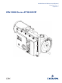
EIM - Series 2000/M2CP (E796) Owner's manual
- Type
- Owner's manual
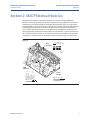
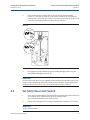
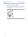
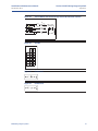
EIM - Series 2000/M2CP (E796) is a modular control package for actuators. It is used to control the operation of valves, sluice gates, and dampers. The M2CP can be configured to meet the specific requirements of each application. Some of the features of the M2CP include:
- Multiple control options, including pushbuttons, remote control, and computer control
- Torque and position limit switches to protect the actuator and valve from damage
- A variety of feedback options, including analog, digital, andHART®
- The ability to be used in a variety of applications, including industrial, commercial, and residential


-
 1
1
-
 2
2
-
 3
3
-
 4
4
-
 5
5
-
 6
6
-
 7
7
-
 8
8
-
 9
9
-
 10
10
-
 11
11
-
 12
12
-
 13
13
-
 14
14
-
 15
15
-
 16
16
-
 17
17
-
 18
18
-
 19
19
-
 20
20
-
 21
21
-
 22
22
-
 23
23
-
 24
24
-
 25
25
-
 26
26
-
 27
27


EIM - Series 2000/M2CP (E796) Owner's manual
- Type
- Owner's manual
EIM - Series 2000/M2CP (E796) is a modular control package for actuators. It is used to control the operation of valves, sluice gates, and dampers. The M2CP can be configured to meet the specific requirements of each application. Some of the features of the M2CP include:
- Multiple control options, including pushbuttons, remote control, and computer control
- Torque and position limit switches to protect the actuator and valve from damage
- A variety of feedback options, including analog, digital, andHART®
- The ability to be used in a variety of applications, including industrial, commercial, and residential
Ask a question and I''ll find the answer in the document
Finding information in a document is now easier with AI
Related papers
-
EIM MCP (E1195) Owner's manual
-
-
-
-
-
-
-
-
-
Baldor 15H SERIES 15H User manual
Other documents
-
Emerson EIM 2000 Series Installation and Maintenance Manual
-
Kohler K-15850-4M-CP Installation guide
-
-
Ralph Lauren RL 3320 Installation guide
-
Omron E2K-F User manual
-
-
Johnson Controls VA-9070 User manual
-
-
Linear VS-GSWG Series Installation guide
-
 PS Automation PSR-E50 Operating Instructions Manual
