Setting Up Your
Dell EMC PowerVault ME4
Series Storage System
© 2019 Dell Inc. or its subsidiaries.
2019-10
1 Before you begin
WARNING: Before you set up and operate your Dell EMC storage system,
review the safety instructions that came with it.
Unpack storage system equipment
An ME4 Series storage system includes:
2 Mount the enclosures
WARNING: Potential injury: chassis is heavy.
Use at least two people to mount a 2U chassis. Use a mechanical lift to mount a 5U chassis.
The rack may fall over if allowed to become top-heavy. Load the rack from the
bottom up with the heaviest chassis at the bottom.
Secure the controller enclosure to the rack using the mounting screws located in the
plastic bag.
2U enclosure
1. Remove the rack mounting rail kit from the box and inspect for damage:
a. Set each location pin at the rear of the rail into a rear rack post hole. Attach the bracket
to the rear rack post: use the washers and screws supplied. Leave the screws loose.
b. Extend the rail to fit between the front and rear rack posts, and attach the
bracket to the front rack post using the washers and screws supplied.
c. Tighten the two clamping screws located along the inside of the rear section of
the rack bracket.
d. Repeat the above sequence of steps for the companion rail.
2. Install the enclosure into the rack:
a. Keeping the enclosure level, carefully insert the chassis slides into the rack rails
and push fully in.
b. Tighten the mounting screws in the rear kit brackets.
Scan to see how-to videos, documentation,
and troubleshooting information.
Quick Resource Locator
Dell.com/QRL/Storage/ME4series
Figure 1. 2U enclosure
Figure 3. 2U rack mount
Figure 4. 5U rack mount
Figure 2. 5U enclosure
c. Remove the enclosure until it reaches the end and hard stops approximately 400 mm
(15.75 inches). Tighten the mounting screws on the front of the rail kit bracket.
d. Return the enclosure to the fully home position.
5U enclosure
The 5U enclosure is shipped without the disks installed. Before mounting, also
remove the rear panel modules to reduce the enclosure weight.
1. With the preassembled rails at their shortest length, locate the rail location
pins inside the front of the rack, and extend the length of the rail assembly to
position the rear location pins. Ensure the pins are fully inserted in the square or
round holes in the rack posts.
2. Fully tighten all clamping screws and middle slide locking screws.
3. Ensure the four rear space clips (not shown) are fitted to the edge of the rack post.
4. Slide the enclosure until it is fully seated on its rails.
A B C
1
2
7
6
8
3
4
5
9
Item Description Item Description
1 Front rack post - square hole 6 Clamping screw (B)
2 Rear rack post - square hole 7 2U enclosure fastening screw (C)
3 Left rail 8 Clamping screw (B)
4 Rail location pins
9
Exploded view of Ops panel cover, to
show left ear ange fastening screw (A)
5 Locking screw
Item Description Item Description
1 Fastening screws (A) 6 Middle slide locking screws
2 Left rail 7 Rear left portion of 5U chassis
3 Rear rack post - square hole 8 Front rack post - square hole
4 Clamping screw (B)
Front left portion of 5U chassis
shown for reference
5 Rail location pins
A B C
8
3
4
1
7
2
5
6
1
4
9
Figure 6. 5U dual–controller cabling (reverse method)
Figure 5. 2U dual–controller cabling: maximum 10 enclosures (reverse method)
0A
1A
2A
3A
0B
1B
2B
3B
0A
1A
2A
9A
0B
1B
2B
9B
5. Fasten the front and rear of the enclosure using the enclosure fastening screws.
CAUTION: Once the enclosure is mounted, dispose of the lifting straps.
The straps are not suitable for reuse.
Reinsert the rear panel modules, and install the disks into the drawers accessed from
the front panel per the instructions in the
Dell EMC PowerVault ME4 Series
Storage System Deployment Guide
.
Expansion cables (1 per expansion module)
Optional enclosure bezel with key (1 per
2U enclosure)
I/O module blank (2U single-controller
storage system only)
Disk drive blank (if 2U storage system is
not fully populated)
Appropriate rackmount kit for 2U or 5U
enclosure
Documentation
2U or 5U enclosure
Power cables (2)
Separately packaged disk drives (5U
enclosure only)
Fibre Channel or iSCSI SFP+ transceivers or
cables (1 per host port)
Host cables (1 per controller module host port)
Develop a configuration plan
Before installing the storage hardware, develop a conguration plan where you can
record host server information, switch information, and network information.
Consider plans for multipath/failover
Redundancy is provided by multipathing, which allows alternate paths if a data path
fails. It is recommended to use multipathing, so that volumes are mapped to ports in
more than one Fibre Channel or iSCSI fabric.
Connect optional expansion enclosures
You can connect a maximum of nine 2U expansion enclosures or three 5U expansion
enclosures to a 2U or a 5U controller enclosure. A 2U controller enclosure can be connected
to a mixture of 2U12 and 2U24 expansion enclosures, or 5U84 only. A 5U controller enclosure
can only be attached to 5U expansion enclosures. Each expansion enclosure includes two
expansion modules.
Figure 5 shows reverse cabling of a dual-controller 2U enclosure and supported
2U expansion enclosures configured with dual expansion modules. Figure 6 shows
reverse cabling of a dual-controller 5U enclosure and supported 5U expansion
enclosures configured with dual expansion modules. Reverse cabling allows any
expansion enclosure to fail—or be removed—while maintaining access to other
enclosures. The middle SAS ports on expansion modules are not used.
3 Connect to the management
network
Each controller’s network port must be connected to a management network.
The network port provides access to management interfaces and is used to send
notifications, SNMP traps, and support data. See figures 7 and 8.
1. Connect an RJ45 Ethernet cable to the network port on each controller.
2. Connect the other end of each Ethernet cable to a network that your
management host can access (preferably on the same subnet).
Notes, cautions, and warnings
NOTE: Indicates important information that helps you make better use of your
product.
CAUTION: Indicates potential damage to hardware or loss of data
and tells you how to avoid the problem.
WARNING: Indicates a potential for property damage, personal
injury, or death.
Figure 7. 2U SAN connections
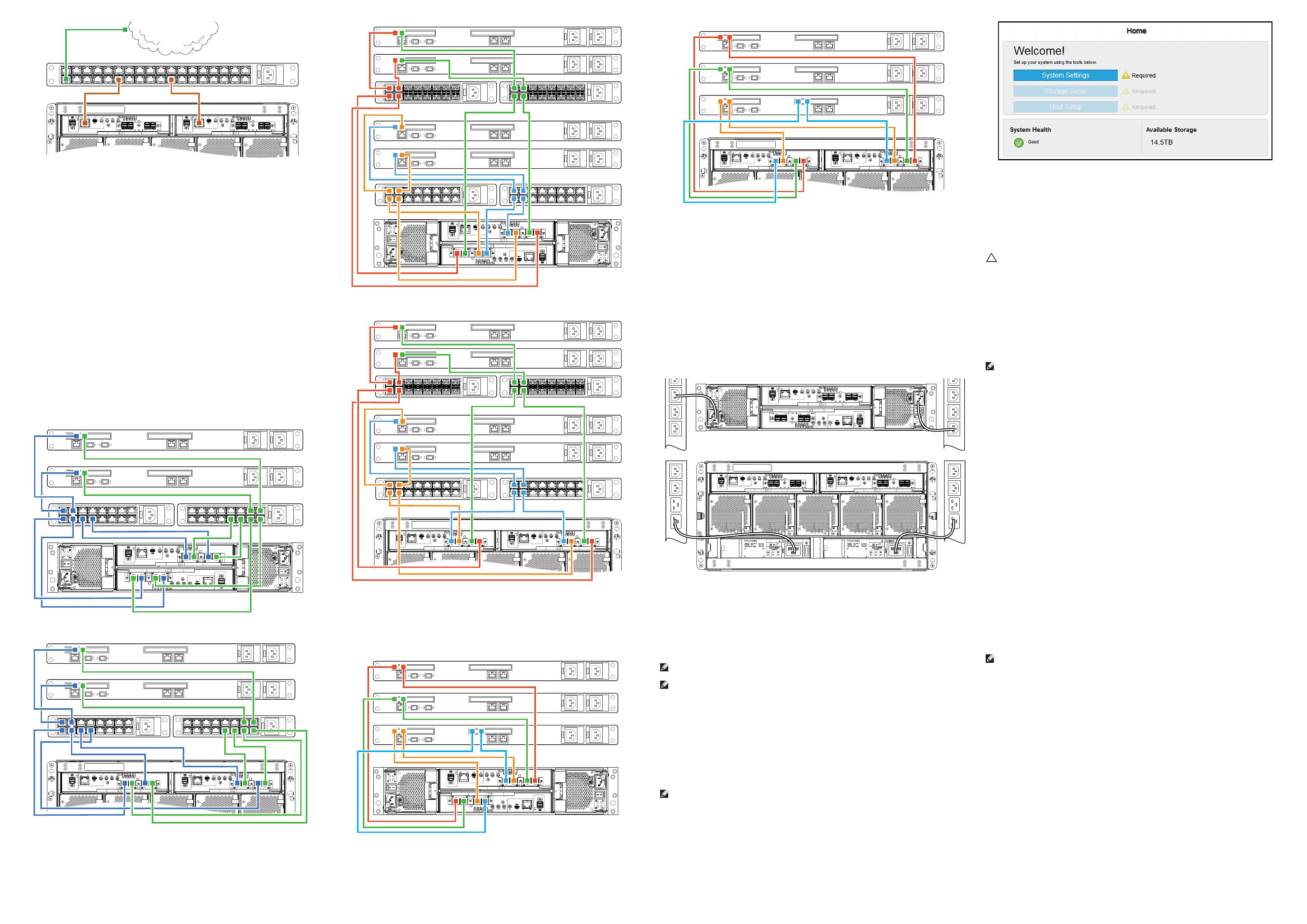
Figure 10. 5U switch attached FC or iSCSI host server connections
Figure 9. 2U switch attached FC or iSCSI host server connections
Figure 11. 2U switch attached FC/iSCSI hybrid host server connections
Figure 13. 2U direct attached SAS host server connections
Figure 14. 5U direct attached SAS host server connections
Figure 8. 5U SAN connections
Figure 16. 5U AC connections
Figure 17. Welcome! screen
Figure 12. 5U switch attached FC/iSCSI hybrid host server connections
SAS
Install and connect each HBA directly to the host ports on the two controllers shown
in figures 13 and 14.
5 Connect power cables and
power on the storage system
When powering on, ensure the enclosures are powered on and associated with
data hosts, in the following order (see figures 15 and 16):
1. Power on any network switches, routers, or other standalone components.
2. Power on any expansion enclosures. Wait until the expansion enclosures are
completely powered up before powering on the controller enclosure.
3. Power on the controller enclosure.
4. Power on the host servers (if powered down for maintenance purposes).
Once powered on, the System Power LED on the 2U Ops panel or the Power on/
Standby LED on the 5U Ops panel turns green.
4 Cable host servers to the
storage system
The storage system can connect to host servers directly or optionally through
switches. For information about switch-attach cabling, see the
Dell EMC
PowerVault ME4 Series Storage System Deployment Guide
. For a list of
supported HBAs or iSCSI network adapters, see the Dell EMC PowerVault ME4
Series Storage System Support Matrix.
Fibre Channel
Install and connect each HBA to a switch that is connected to the host ports
on the two controllers shown in figures 9-12. In hybrid examples, one server and
switch manages FC traffic, and another server and switch manages iSCSI traffic.
For FC, each initiator must be zoned with a single or multiple host ports only
(single initiator/single target or single initiator/multiple target of the same device).
iSCSI
Install and connect each HBA to a switch that is connected to the host ports on
the two controllers shown in figures 9-12.
For iSCSI, use either dedicated switches for iSCSI traffic, or use VLANs when
switches are used for different kinds of IP traffic.
6 Configure the storage system
Temporarily set the management host NIC to a 10.0.0.x. address or to the same IPv6 subnet
to enable communication with the storage system.
Use Mozilla Firefox 57 and later, Google
Chrome 57 and later, or Microsoft Internet Explorer (IE) 10 and 11 browsers to configure the
storage system.
NOTE:
HTTPS must be used to access the storage system during deployment.
NOTE:
Do not turn on more than one unconfigured controller enclosure at a time to
avoid IP conflicts.
In a supported web browser:
1. Type https://10.0.0.2 to access controller A on an IPv4 network.
Type https://fd6e:23ce:fed3:19d1::1 to access controller A on an IPv6 network.
2. Click Get Started. If a license agreement is displayed, click Accept.
3. Set a new username and password for the storage system, then click Apply and
Continue.
4. The Welcome! panel is displayed (figure 17).
NOTE:
If you have a single controller storage system you must select Yes, set my
system to operate with only a single controller on the System Health panel.
5. When first accessing Storage Manager, perform a firmware update before configuring
your storage system. After the firmware update is complete, the Welcome! panel guides
you through system setup, storage setup, and host setup.
7 Perform host setup
For more information about performing host setup, see the
Dell EMC PowerVault
ME4 Series Storage System Deployment Guide
. For a list of supported HBAs or
iSCSI network adapters, see the
Dell EMC PowerVault ME4 Series Storage System
Support Matrix.
CAUTION: Ensure that you assign the correct IP addresses to the HBAs
or network adapters on an iSCSI host. Assigning IPs to the wrong ports
can cause connectivity issues.
Windows and Linux hosts
Install the HBAs or network adapters and make sure that the latest supported BIOS
and drivers are installed.
Attach the hosts to the storage system and install MPIO or DM Multipathing on the
hosts before performing the following steps:
NOTE:
Configure only one host at a time.
Fibre Channel
1. Write down the FC WWN of each HBA to complete the Host Setup Wizard
2. From the Storage Manager interface, run the Host Setup Wizard.
3. Configure MPIO or DM Multipathing for the volumes on the host.
iSCSI
1. Assign IP addresses to each iSCSI port to match the subnets for each
redundant path.
2. Write down the IQNs for each ISCSI initiator/HBA to complete the Host Setup
Wizard.
3. If needed, install and configure the iSCSI software initiator on the host.
4. If using the iSCSI software initiator, it should connect pairs of target/initiator
addresses for multipath using the initiator applet or CLI.
5. Configure MPIO or DM Multipathing for the volumes on the host.
SAS
1. Write down the SAS WWN of each HBA to complete the Host Setup Wizard.
2. From the Storage Manager interface, run the Host Setup Wizard.
3. Configure MPIO or DM Multipathing for the volumes on the host.
VMware ESXi Hosts
Install the HBAs or network adapters and make sure that the latest supported BIOS
and drivers are installed.
Attach the hosts to the storage system before performing the following steps:
NOTE:
Configure only one host at a time.
Fibre Channel
1. Write down the FC WWN of each HBA to complete the Host Setup Wizard.
2. From the Storage Manager interface, run the Host Setup Wizard.
iSCSI
1. If using network adapters, create a VMkernel port for each adapter (one
VMkernel per vSwitch).
2. Assign IP addresses for each adapter port to match the subnets for each
redundant path.
3. If using network adapters, add the VMkernel ports to the iSCSI software initiator.
4. Write down the IQNs for each ISCSI initiator/HBA to complete the Host Setup
Wizard.
5. From the Storage Manager interface, run the Host Setup Wizard.
SAS
1. Write down the SAS WWN of each HBA to complete the Host Setup Wizard.
2. From the Storage Manager interface, run the Host Setup Wizard.
For more detailed information, go to https://www.dell.com/support
Figure 15. 2U AC connections
For more detailed setup information, see the
Dell EMC PowerVault ME4 Series
Storage System Deployment Guide
and
Dell EMC PowerVault ME4 Series Storage
System Administrator’s Guide
at https://www.dell.com/storagemanuals.
  • Page 1 1
  • Page 2 2

Ask a question and I''ll find the answer in the document

Finding information in a document is now easier with AI