Page is loading ...

FLECK SXT TIMER
SERVICE MANUAL
waterpurification.pentair.com

TABLE OF CONTENTS
TABLE OF CONTENTS ..........................................................2
JOB SPECIFICATION SHEET ................................................2
TIMER FEATURES ................................................................3
TIMER OPERATION ..............................................................4
MASTER PROGRAMMING MODE CHART ............................5
MASTER PROGRAMMING MODE .........................................6
MASTER PROGRAMMING MODE
continued ........................................ 7
MASTER PROGRAMMING MODE
continued ........................................ 8
USER PROGRAMMING MODE .............................................. 9
DIAGNOSTIC PROGRAMMING MODE ................................10
2510/2750/2850S TIMER ASSEMBLY ................................. 11
9000/9100/9500 TWIN TANK TIMER ASSEMBLY ...............12
3/4-INCH PLASTIC TURBINE METER ASSEMBLY .............13
PLASTIC PADDLE METER ASSEMBLY ...............................14
3/4-INCH BRASS PADDLE METER ASSEMBLY .................15
1-INCH BRASS PADDLE METER ASSEMBLY ....................16
1-INCH STAINLESS STEEL METER ASSEMBLY ................ 17
INLINE PLASTIC TURBINE METER ASSEMBLY ................18
1-1/2 INCH BRASS METER ASSEMBLY ............................ 19
1-1/2 INCH STAINLESS STEEL METER ASSEMBLY .......... 20
3/4-INCH, 1-INCH or 1-1/2 INCH PADDLE WHEEL METER
CAP ASSEMBLY ..................................................................21
TROUBLESHOOTING .......................................................... 22
2510SXT WIRING DIAGRAM ............................................... 23
2750SXT/2850SXT WIRING DIAGRAM ................................24
9000SXT/9100SXT/9500SXT WIRING DIAGRAM ................25
SERVICE ASSEMBLIES ......................................................26
JOB SPECIFICATION SHEET
Job Number: ______________________________________________
Model Number: ____________________________________________
Water Hardness: __________________________________ ppm or gpg
Capacity Per Unit: __________________________________________
Mineral Tank Size: ___________ Diameter: ________Height: ________
Salt Setting per Regeneration: ________________________________
1. Type of Timer:
A. 7 Day or 12 Day
B. Meter Initiated
2. Downflow: Upflow Upflow Variable
3. Meter Size:
A. 3/4-inch Turbine
B. 3/4-inch Paddlewheel
C. 1-inch Turbine
D. 1-inch Paddlewheel
E. 1-1/2 inch Turbine
F. 1-1/2 inch Paddlewheel
G. Generic ______Pulse Count _______ Model ____________
4. System Type:
A. System #4: 1 Tank, 1 Meter, Immediate, or
Delayed Regeneration
B. System #4: Time Clock
C. System #4: Twin Tank
5. Timer Program Settings:
A. Backwash: ______________________________ Minutes
B. Brine and Slow Rinse:_____________________ Minutes
C. Rapid Rinse: ____________________________ Minutes
D. Brine Tank Refill: ________________________ Minutes
E. Pause Time: ____________________________ Minutes
F. Second Backwash: _______________________ Minutes
6. Drain Line Flow Control: gpm
7. Brine Line Flow Controller: gpm
8. Injector Size#:
9. Piston Type:
A. Hard Water Bypass
B. No Hard Water Bypass
CALIFORNIA PROPOSITION 65 WARNING
WARNING:
This product contains chemicals known to
the State of California to cause cancer or
birth defects or other reproductive harm.
2 • FLECK
SXT Timer Service Manual

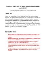
TIMER FEATURES
Parameter
Display
Data
Display
PM
Indicator
Flow Indicator
x1000 Indicator
Service
Icon
Programming
Icon
Extra Cycle
Button
Up
Button
Down
Button
Error/
Information
Icon
Figure 1
Features of the SXT:
• Power backup that continues to keep time and the
passage of days for a minimum of 48 hours in the event
of power failure. During a power outage, the control
goes into a power-saving mode. It does not monitor
water usage during a power failure, but it does store the
volume remaining at the time of power failure.
• Settings for both valve (basic system) and control type
(method used to trigger a regeneration).
• Day-of-the-Week controls.
• While in service, the display alternates between time of
day, volume remaining or days to regeneration, and tank
in service (twin tank systems only).
• The Flow Indicator flashes when outlet flow is detected.
• The Service Icon flashes if a regeneration cycle has
been queued.
• A Regeneration can be triggered immediately by
pressing the Extra Cycle button for five seconds.
• The Parameter Display displays the current Cycle Step
(BW, BF, RR, etc) during regeneration, and the data
display counts down the time remaining for that cycle
step. While the valve is transferring to a new cycle step,
the display will flash. The parameter display will identify
the destination cycle step (BW, BF, RR, etc) and the data
display will read “----”. Once the valve reaches the cycle
step, the display will stop flashing and the data display
will change to the time remaining. During regeneration,
the user can force the control to advance to the next
cycle step immediately by pressing the extra
cycle button.
Setting the Time of Day
1. Press and hold either the Up or Down buttons until the
programming icon replaces the service icon and the
parameter display reads TD.
2. Adjust the displayed time with the Up and Down buttons.
3. When the desired time is set, press the Extra Cycle button
to resume normal operation. The unit will also return to
normal operation after 5 seconds if no buttons are pressed.
Queueing a Regeneration
1. Press the Extra Cycle button. The service icon will flash to
indicate that a regeneration is queued.
2. To cancel a queued regeneration, press the Extra
Cycle button.
Regenerating Immediately
Press and hold the Extra Cycle button for five seconds.
42637 Rev D
FLECK
SXT Timer Service Manual • 3

TIMER OPERATION
Meter Immediate Control
A meter immediate control measures water usage and
regenerates the system as soon as the calculated system
capacity is depleted. The control calculates the system
capacity by dividing the unit capacity (typically expressed
in grains/unit volume) by the feedwater hardness and
subtracting the reserve. Meter Immediate systems
generally do not use a reserve volume. However, in twin
tank systems with soft-water regeneration, the reserve
capacity should be set to the volume of water used during
regeneration to prevent hard water break-through. A Meter
Immediate control will also start a regeneration cycle at the
programmed regeneration time if a number of days equal
to the regeneration day override pass before water usage
depletes the calculated system capacity.
Meter Delayed Control
A Meter Delayed Control measures water usage and
regenerates the system at the programmed regeneration
time after the calculated system capacity is depleted. As
with Meter Immediate systems, the control calculates the
system capacity by dividing the unit capacity by the feedwater
hardness and subtracting the reserve. The reserve should be
set to insure that the system delivers treated water between
the time the system capacity is depleted and the actual
regeneration time. A Meter Delayed control will also start a
regeneration cycle at the programmed regeneration time if a
number of days equal to the regeneration day override pass
before water usage depletes the calculated system capacity.
Time Clock Delayed Control
A Time Clock Delayed Control regenerates the system on a
timed interval. The control will initiate a regeneration cycle
at the programmed regeneration time when the number of
days since the last regeneration equals the regeneration day
override value.
Day of the Week Control
This control regenerates the system on a weekly schedule.
The schedule is defined in Master Programming by setting
each day to either “off” or “on.” The control will initiates a
regeneration cycle on days that have been set to “on” at the
specified regeneration time.
Control Operation During Regeneration
During regeneration, the control displays a special
regeneration display. In this display, the control shows the
current regeneration step number the valve is advancing
to, or has reached, and the time remaining in that step.
The step number that displays flashes until the valve
completes driving to this regeneration step position. Once all
regeneration steps are complete the valve returns to service
and resumes normal operation.
Pressing the Extra Cycle button during a regeneration cycle
immediately advances the valve to the next cycle step position
and resumes normal step timing.
Control Operation During Programming
The control only enters the Program Mode with the valve in
service. While in the Program Mode, the control continues
to operate normally monitoring water usage and keeping
all displays up to date. Control programming is stored in
memory permanently, eliminating the need for battery
backup power.
Manually Initiating a Regeneration
1. When timer is in service, press the Extra Cycle button for
5 seconds on the main screen.
2. The timer advances to Regeneration Cycle Step #1
(Backwash), and begins programmed time count down.
3. Press the Extra Cycle button once to advance valve to
Regeneration Cycle Step #2 (Brine Draw/Rinse).
4. Press the Extra Cycle button once to advance valve to
Regeneration Cycle Step #3 (Rapid rinse).
5. Press the Extra Cycle button once to advance valve to
Regeneration Cycle Step #4 (Brine Refill).
6. Press the Extra Cycle button once more to advance the
valve back to in service.
NOTE: If the unit is a filter or upflow, the cycle step order
may change.
NOTE: A queued regeneration can be initiated by
pressing the Extra Cycle button. To clear a queued
regeneration, press the Extra Cycle button again
to cancel. If regeneration occurs for any reason
prior to the delayed regeneration time, the manual
regeneration request shall be cleared.
Control Operation During A Power Failure
The SXT includes integral power backup. In the event of power
failure, the control shifts into a power-saving mode. The control
stops monitoring water usage, and the display and motor shut
down, but it continues to keep track of the time and day for a
minimum of 48 hours.
The system configuration settings are stored in a non-volatile
memory and are stored indefinitely with or without line power.
The Time of Day flashes when there has been a power failure.
Press any button to stop the Time of Day from flashing.
If power fails while the unit is in regeneration, the control will
save the current valve position before it shuts down. When
power is restored, the control will resume the regeneration
cycle from the point where power failed. Note that if power fails
during a regeneration cycle, the valve will remain in it’s current
position until power is restored. The valve system should
include all required safety components to prevent overflows
resulting from a power failure during regeneration.
The control will not start a new regeneration cycle without
line power. If the valve misses a scheduled regeneration due
to a power failure, it will queue a regeneration. Once power is
restored, the control will initiate a regeneration cycle the next
time that the Time of Day equals the programmed regeneration
time. Typically, this means that the valve will regenerate one
day after it was originally scheduled. If the treated water
output is important and power interruptions are expected, the
system should be setup with a sufficient reserve capacity to
compensate for regeneration delays.
4 • FLECK
SXT Timer Service Manual

MASTER PROGRAMMING MODE CHART
CAUTION
Before entering Master Programming, please contact your local professional water dealer. To enter Master
Programming, set time to 12:01 PM.
Master Programming Options
Abbreviation Parameter Option
Abbreviation
Options
DF Display Format
GAL Gallons
Ltr Liters
VT Valve Type
dF1b Downflow/Upflow Single Backwash
dF2b Downflow Double Backwash
Fltr Filter
UFbd Upflow Brine First
UFtr Upflow Filter
Othr Other
CT Control Type
Fd Meter (Flow) Delayed
FI Meter (Flow) Immediate
tc Time Clock
dAY Day of Week
NT Number of Tanks
1 Single Tank System
2 Two Tank System
TS Tank in Service
U1 Tank 1 in Service
U2 Tank 2 in Service
C Unit Capacity Unit Capacity (Grains)
H Feedwater Hardness Hardness of Inlet Water
RS Reserve Selection
SF Percentage Safety Factor
rc Fixed Reserve Capacity
SF Safety Factor Percentage of the system capacity to be used as a reserve
RC Fixed Reserve Capacity Fixed volume to be used as a reserve
DO Day Override The system’s day override setting
RT Regen Time The time of day the system will regenerate
BW, BD, RR, BF
Regen Cycle Step
Times
The time duration for each regeneration step. Adjustable from
OFF and 0-199 minutes.
NOTE: If “Othr” is chosen under “Valve Type”, then R1, R2,
R3, etc, will be displayed instead
D1, D2, D3, D4, D5,
D6, & D7
Day of Week Settings
Regeneration setting (On or OFF) for each day of the week on
day-of-week systems
CD Current Day The current day of the week
FM Flow Meter Type
P0.7 3/4" Paddle Wheel Meter
Gen Generic or Other Meter
P2.0 2" Paddle Wheel Meter
t1.5 1.5" Turbine Meter
P1.5 1.5" Paddle Wheel Meter
t1.2 1.25" Turbine Wheel Meter
t1.0 1" Turbine Meter
P1.0 1" Paddle Wheel Meter
t0.7 3/4" Turbine Meter
K Meter Pulse Setting Meter pulses per gallon for generic/other flow meter
NOTE: Some items may not be shown depending on timer configuration. The timer will discard any changes and exit Master
Programming Mode if any button is not pressed for sixty seconds.
FLECK
SXT Timer Service Manual • 5

MASTER PROGRAMMING MODE
When Master Programming Mode is entered, all available
option setting displays may be viewed and set as needed.
Depending on current option settings, some parameters
cannot be viewed or set.
Setting the Time of Day
1. Press and hold either the Up or Down buttons until the
programming icon replaces the service icon and the
parameter display reads TD.
2. Adjust the displayed time with the Up and Down buttons.
3. When the desired time is set, press the Extra Cycle
button to resume normal operation. The unit will also
return to normal operation after five seconds if no
buttons are pressed.
Figure 2
Entering Master Programming Mode
Set the Time of Day display to 12:01 P. M. Press the Extra
Cycle button (to exit Setting Time of Day mode). Then press
and hold the Up and Down buttons together until the pro-
gramming icon replaces the service icon and the display
format screen appears.
Exiting Master Programming Mode
Press the Extra Cycle button to accept the displayed settings
and cycle to the next parameter. Press the Extra Cycle but-
ton at the last parameter to save all settings and return to
normal operation. The control will automatically disregard
any programming changes and return to normal operation if
it is left in Master Programming mode for 5 minutes without
any keypad input.
Resets
Soft Reset
Press and hold the Extra Cycle and Down buttons for 25
seconds while in normal Service mode. This resets all
parameters to the system default values. Not reset are the
volume remaining in meter immediate or meter delayed
systems and days since regeneration in the time clock sys-
tem.
Master Reset
Hold the Extra Cycle button while powering up the unit. This
resets all of the parameters in the unit. Check and verify the
choices selected in Master Programming Mode.
1. Display Format (Display Code DF)
This is the first screen that appears when entering Master
Programming Mode. The Display Format setting specifies
the unit of measure that will be used for volume and how
the control will display the Time of Day. This option setting
is identified by "DF" in the upper left corner of the screen.
There are two possible settings.
Display Format
Setting
Unit of Volume Time Display
GAL U.S. Gallons 12-Hour AM/PM
Ltr Liters 24-Hour
Figure 3
2. Valve Type (Display Code VT)
Press the Extra Cycle button. Use the display to set the Valve
Type. 5800 is the only currently available valve type.
3. Regenerant Flow (Display Code RF)
Press the Extra Cycle button. The Regenerant Flow Setting
specifies the type of cycle that the valve follows during regen-
eration. Note that some valve configurations are built with
specific subcomponents. Ensure the valve is configured prop-
erly before changing the Regenerant Flow setting. This option
setting is identified by "RF" in the upper left corner of the
screen. There are eight possible settings.
Abbreviation Parameter
dF1b Standard Downflow Single Backwash
dF2b Standard Downflow Double Backwash
Fltr Filter
dFFF Downflow Fill First
UFbd Upflow Brine First
UFFF Upflow Fill First
UFlt Upflow Filter
O-dF Other Downflow
O-UF Other Upflow
Figure 4
4. Control Type (Display Code CT)
Press the Extra Cycle button. Use this display to set the
Control Type. This specifies how the control determines when
to trigger a regeneration. For details on how the various
options function, refer to the Control Operation section of this
service manual. This option setting is identified by "CT" in the
upper left corner of the screen. There are four possible set-
tings.
6 • FLECK
SXT Timer Service Manual

MASTER PROGRAMMING MODE
CONTINUED
Abbreviation Parameter
Fd Meter (Flow) Delayed
FI Meter (Flow) Immediate
tc Time Clock
dAY Day of Week
Figure 5
5. Unit Capacity (Display Code C)
Press the Extra Cycle button. Use this display to set the Unit
Capacity. This setting specifies the treatment capacity of the
system media. Enter the capacity of the media bed in grains
of hardness when configuring a softener system, or desired
volume capacity when configuring a filter system. This
option setting is identified by "C" in the upper left corner
of the screen (or by "V' if volume capacity for a filter). The
Unit Capacity parameter is only available if the control type
has been set to one of the metered options. Use the Up and
Down buttons to adjust the value as needed.
Figure 6
Range: 1-999.9 x 1000 grains/gallon (mg/liter)
6. Feed Water Hardness (Display Code H)
Press the Extra Cycle button. Use this display to set the Feed
Water Hardness. Enter the feed water hardness in grains
per gallon or degrees for softener systems. This option set-
ting is identified by "H" in the upper left corner of the screen.
The feed water hardness parameter is only available if the
control type has been set to one of the metered softener
options. Use the Up and Down buttons to adjust the value as
needed.
Figure 7
Range: 1-199 grains (degrees)
7. Reserve Selection (Display Code RS)
Press the Extra Cycle button. Use this display to set the Safety
Factor and to select the type of reserve to be used in your sys-
tem. This setting is identified by "RS" in the upper left corner of
the screen. The reserve selection parameter is only available
if the control type has been set to one of the metered options.
There are three possible settings.
Abbreviation Parameter
SF Safety Factor
rc Fixed Reserve Capacity
cr Variable Reserve
Figure 8
8. Safety Factor (Display Code SF)
Press the Extra Cycle button. Use this display to set the Safety
Factor. This setting specifies what percentage of the system
capacity will be held as a reserve. Since this value is expressed
as a percentage, any change to the unit capacity or feed water
hardness that changes the calculated system capacity will
result in a corresponding change to the reserve volume. This
option setting is identified by "SF" in the upper left corner of
the screen. Use the UP and Down buttons to adjust the value
from 0 to 50% as needed.
Figure 9
Range: 0-50%
9. Fixed Reserve Capacity (Display Code RC)
Press the Extra Cycle button. Use this display to set the
Reserve Capacity. This setting specifies a fixed volume that will
be held as a reserve. The Reserve Capacity cannot be set to a
value greater than one-half of the calculated system capacity.
The Reserve Capacity is a fixed volume and does not change
if the unit capacity or feed water hardness are changed. This
option setting is identified by "RC" in the upper left corner of
the screen. Use the Up and Down buttons to adjust the value as
needed.
Figure 10
Range: 0-half of the calculated system capacity
FLECK
SXT Timer Service Manual • 7

MASTER PROGRAMMING MODE
CONTINUED
10. Variable Reserve (Display Code CR)
Press the Extra Cycle button. Use this display to set the
Variable Reserve. This setting is formulated to adjust the
reserve dependant on the previous calendar day's water
usage. During each regeneration, the reserve will change
based on the old reserve capacity and the previous day's water
usage. This option setting is identified by "CR" in the upper left
corner of the screen.
Figure 11
11. Day Override (Display Code DO)
Press the Extra Cycle button. Use this display to set the Day
Override. This setting specifies the maximum number of days
between regeneration cycles. If the system is set to a timer-
type control, the day override setting determines how often
the system will regenerate. A metered system will regenerate
regardless of usage if the days since last regeneration cycle
equal the day override setting. Setting the day override value
to "OFF" disables this function. This option setting is identified
by "DO" in the upper left corner of the screen. Use the Up and
Down buttons to adjust the value as needed.
Figure 12
Range: Off-99 days
12. Regeneration Time
Press the Extra Cycle button. Use this display to set the
Regeneration Time. This setting specifies the time of day the
control will initiate a delayed, manually queued, or day over-
ride regeneration. This option setting is identified by "RT" in
the upper left corner of the screen. Use the Up and Down but-
tons to adjust the value as needed.
Figure 13
13. Regeneration Cycle Step Times
Press the Extra Cycle button. Use this display to set the
Regeneration Cycle Step Times. The different regeneration
cycles are listed in sequence based on the valve type selected
for the system, and are identified by an abbreviation in the
upper left corner of the screen. The abbreviations used are
listed below.
Abbreviation Cycle Step
BD Brine Draw
BF Brine Fill
AD Air Draw
BW Backwash
RR Rapid Rinse
SV Service
If the system has been configured with the "Other" valve type,
the regeneration cycles will be identified as C1, C2, ..., C20.
Cycle steps can be programmed in any order using the Up or
Down buttons with the following selections. Up to 20 individual
cycles can be set. Time for each cycle can be set from 0 to 199
minutes. Setting a cycle step time to 0 will cause the control
to skip that step during regeneration, but keeps the following
steps available. Use the Up and Down buttons to adjust the
value as needed. Press the Extra Cycle button to accept the
current setting and move to the next parameter. Program the
last cycle step as LC which forces the valve back to the service
position.
Abbreviation Cycle Step
RR Rapid Rinse
BD Brine Draw
SR Slow Rinse
BW Backwash
RF Refill
SP Service Position
LC Last Cycle
Figure 14
Range: 0-199 minutes
14. Day of Week Settings
Press the Extra Cycle button. Use this display to set the regen-
eration schedule for a system configured as Day of Week con-
trol. The different days of the week are identified as D1, D2,
D3, D4, D5, D6, and D7 in the upper left corner of the display.
Set the value to "ON" to schedule a regeneration or "OFF" to
skip regeneration for each day. Use the Up and Down buttons
to adjust the setting as needed. Press the Extra Cycle button
to accept the setting and move to the next day. Note that the
control requires at least one day to be set to "ON" If all 7 days
are set to "Off", the unit will return to Day 1 until one or more
days are set to "ON".
Figure 15
8 • FLECK
SXT Timer Service Manual

MASTER PROGRAMMING MODE
CONTINUED
15. Current Day (Display Code CD)
Press the Extra Cycle button. Use this display to set the cur-
rent day on systems that have been configured as Day of Week
controls. This setting is identified by "CD" in the upper left
corner of the screen. Use the Up and Down buttons to select
from Day 1 through Day 7.
Figure 16
16. Flow Meter Type (Display Code FM)
Press the Extra Cycle button. Use this display to set the type
of flow meter connected to the control. This option setting is
identified by "FM" in the upper left corner of the screen. Use
the Up and Down buttons to select one of the eight available
settings.
Abbreviation Description
P0.7 3/4" Paddle Wheel Meter
t0.7 3/4" Turbine Meter
P1.0 1" Paddle Wheel Meter
t1.0 1" Turbine Meter
P1.5 1.5" Paddle Wheel Meter
t1.5 1.5" Turbine Meter
P2.0 2" Paddle Wheel Meter
Gen Generic or Other non-Fleck Meter
t1.2 1.25" Turbine Meter
Figure 17
17. Meter Pulse Setting (Display Code K)
Press the Extra Cycle button. Use this display to specify the
meter pulse setting for a non-standard flow meter. This option
setting is identified by "K" in the upper left corner of the
screen. Use the Up and Down buttons to enter the meter con-
stant in pulses per unit volume.
Figure 18
K Range: 0.1 to 999.9 pulses per gallon.
18. Relay Setting (Display Code RE)
Press the Extra Cycle button. Use this display to enable the
relay output. This option setting is identified by "RE" in the
upper left corner of the screen. Use the Up and Down buttons
to enable the relay using either time based (tb) or flow based
(Fb). Only one method can be used at a time.
For time based, set the desired Start Time (ST) and End Time
(ET). Time ranges available are determined by the Regen Cycle
Step Times. For flow based, set the desired Volume Interval
(VO) and Time On (TO).
Figure 19
Figure 20
ST Range: 0 to total number of cycles minus 1
Figure 21
ET Range: Start time to total of all cycles
Figure 22
Figure 23
VO Range: 1 to Total Gallon Capacity
Figure 24
TO Range: 1 to 7200 (minutes)
19. End of Master Programming Mode
Press the Extra Cycle button to save all settings and exit
Master Programming Mode.
FLECK SXT Timer Service Manual • 9

4. Press the Up button. Use this display to view the Hours in
Service since the last regeneration cycle. This option setting
is identified by "HR" in the upper left corner of the screen.
Figure 27
5. Press the Up button. Use this display to view the Volume
Used since the last regeneration cycle. This option setting
is identified by "VU" in the upper left corner of the screen.
Figure 28
6. Press the Up button. Use this display to view the Reserve
Capacity. This option setting is identified by "RC" in the
upper left corner of the screen.
Figure 29
7. Press the Up button. Use this display to view the Total
Volume data. This option is identified by "TV" in the upper
left corner of the screen.
8. Press the Up button. Use this display to view the Software
Version. This option setting is identified by "SV" in the upper
left corner of the screen.
Figure 30
9. Press the Extra Cycle button to end Diagnostic
Programming Mode.
VIEWING DIAGNOSTIC DATA
The SXT control records and maintains diagnostic data to
assist with servicing and troubleshooting the water treatment
system.
Abbreviation Parameter Description
FR Flow Rate Displays the current outlet
flow rate.
PF Peak Flow Rate Displays the highest flow
rate measured since last
regeneration.
HR Hours in Service Displays the total hours
that the unit has been
in service since last
regeneration.
VU Volume Used Displays the total volume
of water treated by the unit
since last regeneration.
RC Reserve Capacity Displays the system's
reserve capacity calculated
from the system capacity,
feed water hardness, and
safety factor.
TV Totalizer Volume Displays the total volume
of water used by the unit
since last installation or
last reset.
SV Software Version Displays the software
version installed on the
controller.
NOTE:
Some items may not be shown depending on control
configuration. The control will discard any changes
and exit the Diagnostics View if a button is not pressed
for 60 seconds.
Diagnostics View Steps
1. Press the Up and Extra Cycle buttons for five seconds while
in service.
2. Use this display to view the current Flow Rate. This option
setting is identified by "FR" in the upper left corner of the
screen.
Figure 25
3. Press the Up button. Use this display to view the Peak Flow
Rate since the last regeneration cycle. This option setting is
identified by "PF" in the upper left corner of the screen.
Figure 26
10 • FLECK
SXT Timer Service Manual

Item No. QTY Part No. Description
1 ..............1 ...... 13881 ..............Bracket, Hinge Timer
3 ..............1 ...... 14265 ..............Clip, Spring
4 ..............1 ...... 27172 ..............Stand-off, Timer, 2510SXT,
2750SXT
5 ..............1 ...... 21363 ..............Screw, Hex HD, M4 X 12 MM
7 ..............1 ...... 27168 ..............Bracket, Timer,
2510SE/2750SXT
8 ..............3 ...... 13296 ..............Screw, Hex Washer,
6-20 X 1/2
9 ..............1 ...... 42778 ..............Timer, SXT, 2510/2750, DF
9A ............ 1 ...... 19889 ..............Housing, Circuit Board
9B ............1 ...... 42196 ..............Circuit Board, SXT
9C ............ 1 ...... 42635-01 .........Cover, Front, SXT, Square
9D ............1 ...... 42637 ..............Label, Display, SXT
9E ............ 1 ...... 42864 ..............Wire Harness, SXT
Not Shown:
......................... 44144 ..............Transformer, US, 120/24V,
40VA, CEC
......................... 43340 ..............Transformer, Japan, 100/24V,
40 VA
2510/2750/2850S TIMER ASSEMBLY
42778 Rev E
9
3
4
1
2
7
5
9A
9B
9C
9D
8
9E
FLECK SXT Timer Service Manual • 11

9000/9100/9500 TWIN TANK TIMER
ASSEMBLY
Item No. QTY Part No. Description
1 ..............1 ...... 13881 ..............Bracket, Hinge Timer
2 ..............2 ...... 11384 ..............Screw, Phillips, 6-32 X 1/4
3 ..............1 ...... 42732 ..............Bracket, Timer, 9000SXT
4 ..............2 ...... 13296 ..............Screw, Hex Washer Hd,
6-20 X 1/2
5 ..............1 ...... 14265 ..............Clip, Spring
6 ..............1 ...... 42733 ..............Stand-off, Timer, 9000SXT
7 ..............1 ...... 42777 ..............Timer, SXT, D/F, 9000/9100/9500
7A ............ 1 ...... 19889 ..............Housing, Circuit Board
7B ............1 ...... 42196 ..............Circuit Board, SXT
7C ............ 1 ...... 42635-01 .........Cover, Front, SXT, Square
7D ............1 ...... 42637 ..............Label, Display, SXT
8 ..............1 ...... 19474-01 .........Harness, SXT
Not Shown:
......................... 44147 ..............Transformer, US, 120/24V, 9.6VA
......................... 41475 ..............Transformer, Euro, 230/24V, 9.6VA
......................... 43212 ..............Transformer, Aust, 230/24V, 9.6VA
......................... 43340 ..............Transformer, Japan, 100/24V,
9.6VA
42777 Rev D
1
2
4
3
5
6
7A
7B
7C
7D
7
8
12 • FLECK SXT Timer Service Manual

3/4-INCH PLASTIC TURBINE METER
ASSEMBLY
19797 Rev A
Item No. QTY Part No. Description
1 ..............1 ...... 19791-01 .........Meter Cable Assembly,
16 inch long with connector
2 ..............2 ...... 19569 ..............Clip, Flow Meter
3 ..............2 ...... 13314 ..............Screw, Slot Ind Hex,
8-18 x .60
4 ....................... 19797 ..............Meter, 3/4" Turbine, No Clips/Screws
5 ....................... 60626 ..............Meter, 3/4" Turbine, with Clips/Screws
5
4
FLECK SXT Timer Service Manual • 13

PLASTIC PADDLE METER ASSEMBLY
Item No. QTY Part No. Description
1 ..............1 ...... 14716 ..............Meter Cap Assy, NT
(includes items 2, 3, and 4)
2 ..............1 ...... 13874 ..............Cap, Meter, Electronic
3 ..............1 ...... 13847 ..............O-ring, -137, Std, Meter
4 ..............1 ...... 17798 ..............Screw, Slot Hex Washer
Head
5 ..............1 ...... 19121-01 .........Meter Cable Assy, SXT,
Paddle (not included in P/N
60086-50)
6 ..............1 ...... 13821 ..............Body, Meter, 5600
7 ..............1 ...... 13509 ..............Impeller, Meter
8 ..............4 ...... 12473 ..............Screw, Hex Wsh, 10-24 x
5/8
9 ..............4 ...... 13255 ..............Clip, Mounting
10 ............4 ...... 13314 ..............Screw, Slot Ind Hex, 8-18 x
0.60
11 ............4 ...... 13305 ..............O-ring, -119
12 ............1 ...... 14613 ..............Flow Straightener
13 ............1 ...... 60086-50 .........Meter, 3/4", Paddlewheel,
Electronic
5
8
1
2
7
6
9
10
3
4
11
BR60086 Rev E
13
14 • FLECK SXT Timer Service Manual

3/4-INCH BRASS PADDLE METER
ASSEMBLY
Item No. QTY Part No. Description
1 ..............1 ...... 11206 ..............Gasket, Fitting
2 ..............1 ...... 13942 ..............Retainer, Nut
3 ..............1 ...... 11207 ..............Nut, Special, Quick Connect
4 ..............1 ...... 13906 ..............Body, Meter, 3/4-inch
5 ..............1 ...... 13509 ..............Impeller, Meter
....... 13509-01 .........Impeller, Celcon
6 ..............1 ...... 13847 ..............O-ring, -137 Std/560CD,
Meter
7 ..............1 ...... 14716 ..............Meter Cap Assy, ET/NT
8 ..............1 ...... 12473 ..............Screw, Hex Wsh, 10-24 x 5/8
9 ..............1 ...... 60618 ..............Meter Assy, 3/4", Brass, Elec,
Paddlewheel
10 ............1 ...... 19121-01 .........Meter Cable Assembly,
18 inch long with connector
1
2
3
4
5
6
7
8
9
10
FLECK SXT Timer Service Manual • 15

12
11
1-INCH BRASS PADDLE METER ASSEMBLY
Item No. QTY Part No. Description
1 ..............1 ...... 14959 ..............Body, Meter, 2750
2 ..............1 ...... 13882 ..............Post, Meter Impeller
3 ..............1 ...... 13509 ..............Impeller, Meter
4 ..............1 ...... 13847 ..............O-ring, -137, Std/560CD,
Meter
5 ..............1 ...... 14716 ..............Meter Cap Assy, ET/NT
6 ..............4 ...... 12112 ..............Screw, Hex Hd Mach,
10-24 x 1/2
7 ..............1 ...... 14960 ..............Flow Straightener, 1-inch
8 ..............1 ...... 13287 ..............O-ring, -123
9 ..............1 ...... 14961 ..............Fitting, 1-inch Quick Connect
10 ............1 ...... 14962 ..............Nut, 1-inch Meter, Quick
Connect
11 ............1 ...... 60613 ..............Meter Assy, 1", Brass, Elec,
Paddlewheel
12 ............1 ...... 19121 ..............Meter Cable Assembly
....... 19121-08 .........Meter Cable Assembly,
35 inch long with connector
....... 19121-09 .........Meter Cable Assembly,
100 inch long with connector
....... 19121-10 .........Meter Cable Assembly,
304 inch long with connector
16 • FLECK
SXT Timer Service Manual

1-INCH STAINLESS STEEL METER ASSEMBLY
Item No. QTY Part No. Description
1 ..............1 ...... 62049-01 .........Service Kit,
1 inch & 1-1/2 inch Meter,
Standard Range
1 ...... 62049-02 .........Service Kit,
1 inch & 1-1/2 inch Meter,
Extended Range
2 ..............1 ...... 61932-10 .........Meter Assy, 1 inch, Inline,
Stainless Steel, NPT,
Standard Range
1 ...... 61932-11 .........Meter Assy, 1 inch, Inline,
Stainless Steel, NPT,
Extended Range
1 ...... 61932-20 .........Meter Assy, 1 inch, Inline,
Stainless Steel, BSP,
Standard Range
1 ...... 61932-21 .........Meter Assy, 1 inch, Inline,
Stainless Steel, BSP,
Extended Range
3 ..............1 ...... 44022 ..............Union, 1 inch, NPT
(Optional on models with
electronic controls)
1 ...... 44023 ..............Union, 1 inch, BSP
(Optional on models with
electronic controls)
1
3
2
4
4 ..............1 ...... 19791 ..............Meter Cable Assembly
....... 19791-02 .........Meter Cable Assembly,
28 inch long with connector
....... 19791-04 .........Meter Cable Assembly,
100 inch long with connector
....... 19791-05 .........Meter Cable Assembly,
304 inch long with connector
Item No. QTY Part No. Description
FLECK
SXT Timer Service Manual • 17

INLINE PLASTIC TURBINE METER ASSEMBLY
Item No. QTY Part No. Description
1 ..............1 ...... 17542 ..............Flow Straightener
2 ..............2 ...... 40576 ..............Clip, H, Plastic, 7000
3 ..............1 ...... 40577 ..............Turbine Meter Assy, 7000
4 ..............1 ...... 41555 ..............Body, Remote Meter
5 ..............2 ...... 40951 ..............O-ring, -220
6 ..............2 ...... 40563 ..............Connector, 1-inch NPT,
7000
7 ..............2 ...... 40563-10 .........Connector, 1-inch BSP,
7000
8 ..............2 ...... 40565 ..............Connector, 1-1/4 inch NPT,
7000
9 ..............2 ...... 40565-10 .........Connector, 1-1/4 inch BSP,
7000
10 ............2 ...... 41242 ..............Connector, 1-inch &
1-1/4 inch Sweat
11 ............2 ...... 41243 ..............Connector, 1-1/4 & 1-1/2
inch Sweat
12 ............2 ...... 41596 ..............Connector, Brass, 1-inch
NPT
13 ............2 ...... 41596-10 .........Connector, Brass, 1-inch
BSP
14 ............2 ...... 41597 ..............Connector, Brass, 1-1/2
inch NPT
15 ............2 ...... 41597-10 .........Connector, Brass, 1-1/2
inch BSP
Item No. QTY Part No. Description
16
16 ............1 ...... 19791 ..............Meter Cable Assembly
....... 19791-02 .........Meter Cable Assembly,
28 inch long with connector
....... 19791-04 .........Meter Cable Assembly,
100 inch long with connector
....... 19791-05 .........Meter Cable Assembly,
304 inch long with connector
Not Shown
....... 61560 ..............Meter Assy, 1-1/2", Inln, No Thrd
....... 61560-01 .........Meter Assy, 1", NPT, Elec
....... 61560-02 .........Meter Assy, 1", Inln, BSP, Elec
....... 61560-03 .........Meter Assy, 1-1/4", Inln, NPT, Elec
....... 61560-04 .........Meter Assy, 1-1/4", Inln, BSP, Elec
....... 61560-05 .........Meter Assy, 1" & 1-1/4", Inln, Sweat
....... 61560-06 .........Meter Assy, 1-1/4" & 1-1/2", Inln
....... 61560-07 .........Meter Assy, 1", Inln, NPT, Elec
....... 61560-08 .........Meter Assy, 1", Inln, BSP, Elec
....... 61560-09 .........Meter Assy, 1-1/2" Inln, NPT, Elec
....... 61560-10 .........Meter Assy, 1-1/2", Inln, BSP, Elec
....... 61560-11 .........Meter Assy, 3/4", Inln, NPT, Elec
....... 61560-12 .........Meter Assy, 3/4", Inln, BSP, Elec
....... 61560-13 .........Meter Assy, 1-1/2", Inln, NPT
....... 61560-14 .........Meter Assy, 1-1/2", Inln, BSP
18 • FLECK SXT Timer Service Manual

1-1/2 INCH BRASS METER ASSEMBLY
Item No. QTY Part No. Description
1 ..............1 ...... 17569 ..............Body, Meter, 2850/9500
2 ..............1 ...... 13882 ..............Post, Meter Impeller
3 ..............1 ...... 13509 ..............Impeller, Meter
1 ...... 13509-01 .........Impeller, Celcon, Hot Water
4 ..............1 ...... 13847 ..............O-Ring, -137, Std/560CD,
Meter
5A ............ 1 ...... 14038 ..............Meter Cap Assy, STD
Range, Plastic
5B ............1 ...... 15150 ..............Meter Cap Assy, Ext Range,
Plastic
6 ..............4 ...... 12112 ..............Screw, Hex Hd Mach, 10-24
x 1/2 18-8 Stainless Steel
7 ..............1 ...... 17542 ..............Flow Straightener,
1-1/2
inch
8 ..............1 ...... 12733 ..............O-Ring, -132
9 ..............1 ...... 17544 ..............Fitting, 1-1/2
inch Quick
Connector
10 ............1 ...... 17543 ..............Nut, 1-1/2 inch, Q/C
11 ..................... 60610-01 .........Meter Assy, 1-1/2 inch, NPT,
STD, Brass, Paddlewheel
....... 60610-01NP....Meter Assy, 1-1/2
inch
Inline, NPT, STD Brass
Body, Nickel Plated,
Paddlewheel
....... 60610-01HW ... Meter Assy, 1-1/2
inch
Inline, NPT, STD Brass, Hot
Water, Paddlewheel
....... 60610-21 .........Meter Assy, 1-1/2 inch, BSP,
STD, Brass, Paddlewheel
....... 60610-21NP....Meter Assy, 1-1/2
inch
Inline, BSP, STD, Brass
Body, Nickel Plated,
Paddlewheel
....... 60611-01 .........Meter Assy, 1-1/2
inch
Inline, NPT, STD, Brass
Body, Paddlewheel, Sleeve
to 1-inch
....... 60611-01NP....Meter Assy, 1-1/2
inch
Inline, NPT, STD Nickel
Plated, Paddlewheel,
Sleeve to 1-inch
....... 60611-23 .........Meter Assy, 1-1/2
inch Inline, BSP, STD,
Paddlewheel, Sleeve to
1-inch
....... 60611-23NP....Meter Assy, 1-1/2 inch
Inline, BSP/MET STD,
Nickel Plated, Paddlewheel,
1-inch Sleeve
12 ..................... 60610-02 .........Meter Assy, 1-1/2 inch, NPT,
STD, Brass Paddlewheel
....... 60610-02NP....Meter Assy, 1-1/2 inch
Inline, NPT, EXT Nickel
Plate, Paddlewheel
....... 60610-02HW ... Meter Assy, 1-1/2
inch Inline,
NPT, EXT Brass, Hot Water,
Paddlewheel
....... 60610-22 .........Meter Assy, 1-1/2 inch, BSP,
EXT, Brass, Paddlewheel
....... 60610-22NP....Meter Assy, 1-1/2 inch Inline,
BSP EXT, Brass Body, Nickel
Plate, Paddlewheel
....... 60611-02 .........Meter Assy, 1-1/2 inch
Inline, NPT, EXT Brass Body,
Paddlewheel, Sleeve to
1-inch
....... 60611-02NP....Meter Assy, 1-1/2 inch Inline,
NPT, EXT Nickel Plated,
Paddlewheel, Sleeve to
1-inch
....... 60611-22 .........Meter Assy, 1-1/2 inch
Inline, BSP, EXT Brass Body,
Paddlewheel, Sleeve to
1-inch
....... 60611-22NP....Meter Assy, 1-1/2
inch
Inline, BSP, EXT, Nickel,
Paddlewheel, Sleeve to
1-inch
13 ............1 ...... 19121 ..............Meter Cable Assembly
....... 19121-08 .........Meter Cable Assembly,
35 inch long with connector
....... 19121-09 .........Meter Cable Assembly,
100 inch long with connector
....... 19121-10 .........Meter Cable Assembly,
304 inch long with connector
Not Shown
1 ...... 17790 ..............Sleeve, Meter, 1 1/2
inch x
1-inch
1 ...... 15218 ..............Meter Cap Assy, STD Range,
Brass, Hot Water
1 ...... 15237 ..............Meter Cap Assy, EXT Range,
Brass, Hot Water
Item No. QTY Part No. Description
1
2
3
4
6
1211
7
8
9
10
5A
5B
FLECK SXT Timer Service Manual • 19

Item No. QTY Part No. Description
1 ..............1 ...... 62049-01 .........Service Kit,
1 inch & 1-1/2 inch Meter,
Standard Range
1 ...... 62049-02 .........Service Kit,
1 inch & 1-1/2 inch Meter,
Extended Range
2 ..............1 ...... 61933-10 .........Meter Assy, 1-1/2 inch,
Inline, Stainless Steel, NPT,
Standard Range
1 ...... 61933-11 .........Meter Assy, 1-1/2 inch,
Inline, Stainless Steel, NPT,
Extended Range
1 ...... 61933-20 .........Meter Assy, 1-1/2 inch,
Inline, Stainless Steel, BSP,
Standard Range
1 ...... 61933-21 .........Meter Assy, 1-1/2 inch,
Inline, Stainless Steel, BSP,
Extended Range
3 ..............1 ...... 44024 ..............Union, 1-1/2 inch, NPT
(Optional on models with
electronic controls)
1 ...... 44025 ..............Union, 1-1/2 inch, BSP
(Optional on models with
electronic controls)
1
3
2
4
1-1/2 INCH STAINLESS STEEL METER ASSEMBLY
4 ..............1 ...... 19791 ..............Meter Cable Assembly
....... 19791-02 .........Meter Cable Assembly,
28 inch long with connector
....... 19791-04 .........Meter Cable Assembly,
100 inch long with connector
....... 19791-05 .........Meter Cable Assembly,
304 inch long with connector
Not Shown (optional)
1 ...... 62072 ..............Meter Sleeve,
1-1/2 inch to 1 inch (optional)
Item No. QTY Part No. Description
20 • FLECK SXT Timer Service Manual
/