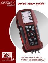
UEi C163 User manual

Category
Measuring, testing & control
Type
User manual
1-800-547-5740 • Fax: (503) 643-6322
www.ueitest.com • Email: [email protected]
INSTRUCTION MANUAL
ENGLISH
C163
Residential / Commercial Combustion Analyzer with Heat Exchanger Test
C
o
m
b
u
s
t
i
o
n
A
n
a
l
y
z
e
r
C
O
C
O
2
T
E
M
P
Status
v3
Aux
O2/Eff CO/CO2 Temp
Exch Test
C163
BACKED BY
2
FUNCTIONS
Measures: CO, CO2, Flue Temperature, Inlet temperature
Calculates:
O2, Differential Temperature, CO/CO2 Ratio, Efficiency (Net, Gross, High C), Excess Air,
CO/CO2, Losses, Differential
Pressure
FEATURES
TABLE OF CONTENTS
Functions .............................................2
Features ..............................................2
General Specifications ................................3
Important Safety Warnings. . . . . . . . . . . . . . . . . . . . . . . . . . . . .3
Symbols ..............................................4
Analyzer Overview ..................................4-5
Overview ...........................................6
Pre Test Checklist ...................................6
Setting Inlet Temperature ...........................6
Analyzer Connections ...............................6
Emptying & Cleaning the In-Line Water Trap .........7
Changing The Particle Filter .........................7
Quick Start ..........................................7
Fresh Air Purge ......................................7
Over-Range Pump ...................................7
Measuring Flue Gases ...............................7
Display Parameters ................................8-9
Status Screen .......................................9
Status Bar ..........................................10
Status Bar Icons ...................................10
Status Bar Icon Layout ..............................10
Status Bar Menu Options ............................10
Status Bar Options Table ............................10
Menu ............................................10-11
Using the Menu ...................................10
Menu Items .......................................11
Stored Logs Memory ............................. 11-13
Menu Options .....................................12
Viewing Stored Logs ................................12
Log View Menu Options .............................12
Navigating Stored Logs .............................12
Log Navigation Menu Options ........................13
Pressure/Temperature Testing ...................13-14
Pressure Testing (if Pressure Fitted) ....................13
Pressure Measurement Good Practice ..................13
Large Bore Tubing Issues ............................13
Heat Exchanger Test ..................................14
Viewing/Printing .....................................14
Printouts ...........................................15
Specifications ......................................16
Certification ........................................16
Where to Test ...................................17-18
What Results are Generally Acceptable ............18
What Results Are Generally Acceptable ................18
Typical Excess Air Level .............................18
Powering Off .......................................19
Post Test ...........................................19
General Maintenance ..............................19
Cold Weather Precautions ..........................19
Replacing the Batteries ............................20
Annual Service & Recertification ...................20
Recertification Services ............................21
Returning Your Analyzer ............................21
Where to Send Your Analyzer .......................21
Other Important Factors Relating to Combustion ....22
Combustion Measurement Terms ...................22
Net Temperature ...................................22
Draft ............................................22
Efficiency .........................................22
Combustion Efficiency Calculations ....................22
CO Air Free .......................................22
Disposal ............................................24
Cleaning ...........................................24
Storage .............................................24
Warranty ...........................................24
EOS Technology
Over-Range Protection Pump
NOx Filtered CO Sensor
Large 6 line Backlit Display
Water Trap Indicator
High Altitude Compensation
Wireless BT Module
Low Flow Detection
Memory: 30 logs
3
GENERAL SPECIFICATIONS
IMPORTANT SAFETY WARNINGS
Read entire Safety Notes section regarding potential hazard and proper instructions before using this analyzer. In this manual the
word “WARNING” is used to indicate conditions or actions that may pose physical hazards to the user. The word “CAUTION” is used to
indicate conditions or actions that may damage this instrument. This analyzer must only be used in well-ventilated locations by trained
and competent persons after due consideration of all potential hazards.
WARNING
To ensure safe operation and service of the tester, follow these instructions. Failure to observe these warnings can result in severe
injury or death.
WARNING
• Do not use this analyzer during electrical storms or in wet weather.
• To avoid false readings, charge batteries if a low battery indicator appears. (If fitted with rechargeable batteries)
• Always adhere to national and local safety codes. Use proper personal protective equipment (PPE).
WARNING
This analyzer extracts combustion gases that may be toxic in relatively low concentrations. These gases are exhausted from the back
of the analyzer.
WARNING
This analyzer is designed for trade professionals who are familiar with the hazards of their trade. Observe all recommended safety
procedures that include proper lockout utilization and use of personal protective equipment that includes safety glasses, gloves and
flame resistant clothing.
Users of portable gas detectors are recommended to conduct a “bump” check before relying on the unit to verify an atmosphere is free
from hazard. A ‘bump” test is a means of verifying that an instrument is working within acceptable limits by briefly exposing to a known
gas mixture formulated to change the output of all the sensors present.
NOTE: This is different from a calibration where the instrument is also exposed to a known gas mixture but is allowed to settle to a
steady figure and the reading adjusted to the stated gas concentration of the gas of the test gas.
Operating Temperature: 0˚ to 113˚F (-18˚ to 45˚C)
Storage Temperature: 0˚ to 113˚F (-18˚ to 45˚C)
Operating Humidity: 15% to 90% R.H.
Back light: Yes
Dimensions: 8.54 x 4.18 x 1.86 inch
Item Weight: 1.5 lb
Calibration: Recommended Annually
Certification: CE Conformity, RoHS, REACH Compliant,
AHRI 1260 standard
Battery Type: NiMH (AA) 3
Accuracy: ± (% of reading + # of least significant digits)
4
ANALYZER OVERVIEW
A. Infrared Printer Port
B. On/ Off (Power) Button
C. 6 Line Backlit Display
Press any button to turn Back light on (will turn off after 10 seconds of inactivity)
D. Protective Rubber Boot With Magnets
E. Status Bar
F. Data Hold Button: Short press to hold current data
G. Pump Toggle Button: Long press to toggle pump on and off
H. UP Button
Short press to navigate “UP”
I. Save Log Button: Long press to store data
J. Print Report Button: Short press to a report (will enter a print option if both Wireless Module is fitted)
K. Down Button
Short press to navigate “DOWN”
L. Enter Button: Long press to store data
Short press select current option displayed
Long press to activate some menu items
M. Rotary Selector Dial
N. Particle Filter (inside water trap)
O. Water Trap
P. LED Water Trap Full Indicator
Q. Serial Number: (under protective boot)
R. Sensors Fitted: (label under Protective Boot) Indicates Sensors fitted in unit
S. Battery Compartment: (under Protective Boot)
T. Grip Indentation: Indentation for fingers to grip analyzer
U. Water Trap Drain Plug (Red plug; take caution NOT to damage plug when removing protective boot)
V. Battery Charge USB Adapter Connection
W. Temperature Connections
Flue Probe Temperature: T1
Inlet Temperature: T2
X. Flue Gas Inlet Connection
Y. Pressure Ports (C163 & C164 Only)
Pressure Port 1
Pressure Port 2
SYMBOLS
Low battery Degrees Fahrenheit
Degrees Celsius Pump Status
Pump Start Pump Stop
Hold Printing
Navigate Down Navigate Up
Enter Key Save Log
5
ANALYZER OVERVIEW (CONT.)
A
C
o
m
b
u
s
t
i
o
n
A
n
a
l
y
z
e
r
C
O
C
O
2
T
E
M
P
Status
v3
Aux
O2/Eff CO/CO2 Temp
Exch Test
C163
Serial No.
Sensors
Fitted:
CO CO2 NO O2
B
C
D
E
F
G
H
I
J
K
L
M
P
O
N
S
U
T
R
Q
WV X
Narrow Pin MUST be on the
Right hand side.
Flue Probe Temperature Plug
(Plugs into T1)
Flue Probe
Gas Inlet Plug
Red Connector
(plugs into Flue
Gas Inlet)
T2 T1
P2 P1
Y
6
OVERVIEW
The direct measurement of CO2 is achieved using UEi’s own EOS technology sensor. CO2 is set to zero in fresh air automatically after
the initial 60 second countdown.
If “ZERO CO2” is indicated, ensure the unit is in outside fresh air before selecting the “Purge” option.
It is very important that re-zeroing is done in outside fresh air as indoor CO2 levels are affected by human breath.
The analyzer has a protective rubber boot with magnets for hands-free operation and is supplied with a probe with an integral
temperature sensor.
A low flow detection system warns of a low flow and switches the pump off, this also helps prevent water ingress from overfilled water
traps.
A large 6 line display provides the user with relevant information based on current activity including instrument status via the new
intelligent Status Bar. All data can be printed via the infrared printer.
These analyzers use a new data storage system allowing the user to store the maximum number of logs of interest to them, rather than
be restricted to an allowance of particular logs.
The memory can store up to 30 logs of any combination of Combustion, AUX or Pressure/Temperature tests.
10 characters can be added to Line 1 of the header, 6 characters to Line 2 of Header of the printouts.
The C163 and C164 all have a Wireless Connection that connects to a Free App, Kane Wireless Printer, available through iOS® and
Android.
PRE TEST CHECKLIST
SETTING INLET TEMPERATURE
ANALYZER CONNECTIONS
Turn on and zero the analyzer, without the flue probe connected, to use ambient temperature
Connect the flue probe thermocouple to T1 during zero countdown use for inlet ducted system
Connect a thermocouple to T2 to measure second temp source
Clean particle filter
Water trap and probe line are empty of water
Power on and zero
All hose and thermocouple connections are properly secured
Flue gas probe is sampling ambient FRESH air
Water trap is fitted correctly to the instrument
Flue temperature plug is connected
Ensure water trap plug is inserted correctly
WARNING
Turning the pump off while the probe is in the flue will leave toxic gases inside the analyzer. Once
data has been printed or copied, it is advisable to purge the unit with fresh air as soon as possible.
To do this remove the probe from the flue and turn ON pump. Always allow the readings to return to
zero (20.9% for O2) prior to shutting the unit off. The meter will not switch off until the CO reading is
below 20 ppm.
CAUTION!
The probe will be hot from flue gases. Remove the probe from the flue and allow it to cool naturally.
Do not immerse the probe in water, as this will be drawn into the analyzer and damage the flue
probe and the pump and sensors. NOTE: Take care when
inserting the temperature
probes as the pins are
polarized. Insert with the
smaller pin (+) to the right.
T2 T1
P2 P1
7
Remove the protective rubber boot
Slide the water trap unit from the analyzer
Remove the particle filter from its’ spigot and replace
Slide the water trap back into position and replace the protective rubber boot
FRESH AIR PURGE
WARNING
Each time the analyzer is turned on it will perform a 60 second air purge, this is to clear the gas
sampling path (including probe, if connected). For these reasons it is very important that the analyzer
be in outside fresh air when powered on.
When in the Rotary Dial positions AUX, Flue 1 or Flue 2 ; Press the Up or Down Buttons, scroll to CO2
Zero. On the Purge option, short press the ENTER Button, and a 60 second Purge will begin.
STATUS
FLUE 1
AUX
FLUE 2
TEMP
C
o
m
b
u
s
t
i
o
n
A
n
a
l
y
z
e
r
C161
C
O
C
O
2
T
E
M
P
EMPTYING & CLEANING THE IN-LINE WATER TRAP
CHANGING THE PARTICLE FILTER
QUICK START
Turn on the analyzer by pressing the On/Off Button for 2 seconds until the unit activates. As described the analyzer will perform a 60
second turn on purge. Once completed simply select the reading desired by the position of the rotary dial.
MEASURING FLUE GASES
After the initial countdown is finished and the analyzer is properly setup, put its’ flue probe in the appliance’s sampling point. The tip of
the probe should be at the center of the flue. Use the flue probes depth stop cone to set the position.
With balanced flues, make sure the probe is positioned into the flue so no air can “back flush” into the probe.
CAUTION!: Ensure the flue probe handle does not get hot!
20”
Boiler
Flue
Remove the rubber plug
Allow the water to drain out
Re-insert the rubber plug
OVER-RANGE PROTECTION PUMP
The analyzer’s intelligent protection system will automatically activate the over-range protection pump once an over-gas condition is
detected above 2000ppm. When activated the main sampling pump will be shut down, allowing the sample system to be purged with
fresh air. Once readings have returned to a safe level, the protection pump will shut down and the main pump will reactivate.
8
DISPLAY PARAMETERS
The large display is backlit with 6 lines, the last line is the Status Bar line.
Menu Screen
Time (settable parameter; HH:MM:SS, displayed in 24 hour clock format)
Date (settable parameter; DD:MM:YY)
Header (settable parameter; 16 character, 2 line; 10 characters can be added to Line 1 of the header, 6 characters to Line 2)
IR Print (KMIRP2 or IRP-2)
˚C/˚F (settable parameter)
NOx Ref (settable parameter; select 0.0% to 20.0%)
Gas Unit (settable parameter; select between ppm(n), ppm, mg/kWh(n), mg/kWh, mgm3(n), mgm3)
Language (settable parameter; select between English, Espanol, Francais)
EFF (Efficiency - settable parameter; select between Nett or Gross
O2 Ref (settable parameter; select 0.0% to 20.0%)
Logs (if logs are saved, options displayed; COMB., AUX, PRS/TMP, MEM)
Code (for Authorized Service Personnel only)
AUX Screen
(Default selections can be changed by user to desired selections; select between O2, CO, NO, Display Fuel Type, CAL, XAIR, LOSS,
EfGc, ATM, Ti, ∆T, T2, T1, CO2, COa, or COn, P1, P2)
Default Selections Are:
O2 (displayed in %)
COn (displayed in p)
CO2 (displayed in %)
NOn (displayed in p)
NOxn (displayed in p)
Flue 1 Screen
Default Selections Are:
O2 (displayed in %)
COn (displayed in p)
CO2 (displayed in %)
NOn (displayed in p)
NOxn (displayed in p)
9
Flue 2 Screen
CO (displayed in ppm)
COa (O2++ displayed in ppm)
CO2 (displayed in %)
Loss (displayed in %)
XAIr (Excess Air, O2++ displayed in ppm)
Temp/Prs Screen
Default Selections Are:
T1 (displayed in F or C)
T2 (displayed in F or C)
∆T (displayed in F or C)
P (displayed in unit selected; mBar, InH20, hPa, mmHg, PSI, kPa, Pa, mmH20)
Exch Test Screen
Default Selections Are:
O2 (displayed in %)
COn (displayed in p)
CO2 (displayed in %)
NOn (displayed in p)
NOxn (displayed in p)
STATUS SCREEN
Select “Status” on the dial to view the following:
Current fuel selection. Use status bar to change fuel selection.
Select between: Pellets, Light Oil, Heavy Oil, LPG, Butane, Propane, Natural Gas, Bio Oil
Ambient temperature around the analyzer.
Current atmospheric pressure (mBar).
Shows number of days until next calibration is due.
User Interface
The large six-line display will indicate 5 lines and the status bar (see pg. 10) the backlight will activate on each button press and turn off
after 10 seconds of no activity. Navigation through the various start options and menu system is via the 3 button dedicated Up, Down &
Enter Buttons. Button presses are categorized short press and long press
Status Bar
The Status Bar provides the user with a concise indication of the instrument status, it incorporates an intelligent system that
understands what the user is currently viewing on the display offering appropriate menu items as well as standard menu items.
Navigation through the Status Bar options is achieved via the and buttons when the Status Bar is visible on the display.
STATUS
FLUE 1
AUX
FLUE 2
TEMP
C
o
m
b
u
s
t
i
o
n
A
n
a
l
y
z
e
r
C161
C
O
C
O
2
T
E
M
P
10
STATUS BAR
Status Bar Icons
The icons are designed to provide quick and simple instrument status information without having to navigate complicated menu
systems or detract from the job at hand.
Status Bar Icon Layout
Status Bar Menu Options
The Status Bar will offer the user Menu items based on the Selector Dial setting.
Status Bar Options Table
Dial Position
Status Info Available STATUS AUX FLUE 1 FLUE 2 TEMP/PRS
TIME 44444
FLUE SELECTED 44444
DATE 44444
CO2 ZERO EDIT 4 4 ZERO PRS
PRS UNIT
Date Option Date Displayed as
MENU
Using the Menu
The Menu position on the Rotary Dial allows for the customization of the default settings for the analyzer as per the user’s
requirements. Navigation through the Menu system is via the dedicated user’s interface buttons (Up, Down, Enter).
As you navigate up or down through the Menu, the items will scroll accordingly, eventually back to the beginning.
Rotate Selector Dial to MENU to set up or customize your settings.
Selected parameter are centered, highlighted with arrow icons on either side.
Use and buttons to scroll menu options.
Press to a select a parameter to edit. Press button to scroll fields to change.
Press and buttons to change field contents.
Press to enter content selected.
Pump
Pump
Sending Data
Battery
Pump on
Pump paused
Indicates data is being transmitted to either the
App or the Printer
Battery Status indication
STATUS
FLUE 1
AUX
FLUE 2
TEMP
C
o
m
b
u
s
t
i
o
n
A
n
a
l
y
z
e
r
C161
C
O
C
O
2
T
E
M
P
11
Menu Items
MENU Sub Menu OPTIONS/COMMENTS
Time HH:MM:SS 24 Hour Format (e.g. 7AM = 0:00:00, 7PM = 19:00:00)
Date DD/MM/YY
Header LINE 1 Customer info displays on print outs
LINE 2 Customer info displays on print outs
EXIT
IR Print KMIRP Select to print to KMIRP
IRP-2 Select to print to IRP-2
Temperature Scale ˚C Select ˚F or ˚C.
˚F
Gas Unit ppm
ppm(n)
mg/m3
mg/m3(n)
mg/kWh
mg/kWh(n)
Language English
Espanaol
Francais
Efficiency Gross
Nett
O2 ref Used for "Normalized" readings. Default set to 3%, can be adjusted up or down.
Logs VIEW View current memory usage and view stored Logs
DELETE ALL
EXIT
Code Password protected for authorized service agents only/ LEAVE SET TO "0000".
STORED LOGS MEMORY
The UEi utilizes a shared memory system much like a computer hard drive. The different Log types are stored sequentially until the
shared memory area is full. This means the Log types are not restricted to a smaller number of memory locations as the full memory
capacity is available as required for Logs of any type.
To view the current memory usage status simply navigate to menu -----> LOGS, press the button to select the Log desired.
Number of stored Combustion Logs
Number of stored Auxiliary Logs
Number of stored Temperature Logs and “Pressure if fitted”
Total Memory Used
Menu Options
To veiw entire Log, results must be printed to App or through IR printer.
View stored Logs, this will enter the secondary menu to select the type of log to view (will only
appear if data available). (Results must be printed to app or through IR printer)
Delete all stored Logs. To delete “long press” the button (will only appear if data available).
Exit back to the Main Menu
STATUS
FLUE 1
AUX
FLUE 2
TEMP
C
o
m
b
u
s
t
i
o
n
A
n
a
l
y
z
e
r
C161
C
O
C
O
2
T
E
M
P
12
Viewing Stored Logs
Once the view has been selected from the Logs Menu the following screen will be displayed:
List of available Logs (Navigation and selection via the , and buttons).
Log View Menu Options
View stored Combustion Logs (Option will appear if Logs are available).
View stored Auxiliary Logs (Option will appear if Logs are available).
Number of stored Temperature Logs and “Pressure if fitted” (Option will appear if
Logs are available).
Exit back to previous menu
Navigating Stored Logs
Once the desired Log type to view has been selected, the first available stored Log will be displayed.
Log Number
Log time and date (this line will alternate between time and date of Log)
Log readings (information is specific to Log type)
Navigation Menu options (Results must be printed to app or through IR printer)
To veiw entire Log, results must be printed to App or through IR printer.
Log Navigation Menu Options
Print the currently selected Log
Navigate to the next available Log of the selected type (Option will only appear if there is more than
one Log).
Navigate to the previously selected Log of the selected type (Option will only appear if there is more
than one Log).
Exit back to the previous menu.
STATUS
FLUE 1
AUX
FLUE 2
TEMP
C
o
m
b
u
s
t
i
o
n
A
n
a
l
y
z
e
r
C161
C
O
C
O
2
T
E
M
P
13
TEMPERATURE TESTING
Select the Temperature Rotary Dial position.
STATUS
FLUE 1
AUX
FLUE 2
TEMP
C
o
m
b
u
s
t
i
o
n
A
n
a
l
y
z
e
r
C161
C
O
C
O
2
T
E
M
P
Use the T1 connection for the Flue Probe temperature sensor
Use the T2 connection for the Inlet temperature sensor
Real time temperature difference
Real time pressure reading (pressure will only show is fitted)
PRESSURE TESTING
WARNING
Never attempt to take a pressure reading without knowing the maximum pressure that might be present.
This instrument’s pressure transducer is rated at 2.3in H20 with a maximum pressure over range of 11.8in H20.
Using the black connectors and the manometer hose. Connect P1 for a single pressure or P1 and P2 for differential pressure.
STATUS
FLUE 1
AUX
FLUE 2
TEMP
C
o
m
b
u
s
t
i
o
n
A
n
a
l
y
z
e
r
C161
C
O
C
O
2
T
E
M
P
Use the T1 connection for the Flue Probe temperature sensor
Use the T2 connection for the Inlet temperature sensor
Real time temperature difference
Real time pressure reading (pressure will only show is fitted)
PRESSURE MEASUREMENT GOOD PRACTICE
WARNING
Before using the analyzer to measure the pressure of a gas/air ratio valve, read the boiler manufacturer’s manual thoroughly. If in
doubt, contact the boiler manufacturer. After adjusting a gas/air ratio valve, it is essential the CO, CO2, CO/CO2 ratio readings are with-
in the boiler manufacturer’s specified limits.
LARGE BORE TUBING ISSUES
If using larger bore tubing when performing pressure tests:
Push tubing over the rim of the This may not produce a gas tight seal.
spigot to ensure a gas tight seal.
14
In Heat Exch Setup Screen, select Fuel type (Natural Gas, Bio Oil, Heavy Oil, Pellets, Light Oil, LPG,
Butane, Propane)
HEAT EXCHANGER TEST
NOTE: Test results; O2, CO and Excess Air will show on the printout.
There are many methods to test heat exchanger integrity. One of these is to observe the Excess Air, O2 and CO readings both before
and after the blower turns on. If the heat exchanger is sealed your O2 and CO readings should remain fairly stable. A breach in the heat
exchanger may allow fresh air to be forced into the flue after the blower turns on due to a pressure increase in the plenum. The result
may be a rise in the measured O2 in the stack gas and an increase in the Excess Air . In some sealed systems the fresh air drawn in
through the breach may reduce the combustion air available leading to an increase in the CO reading. If either of these situations are
present it is probable that there is a problem with the Heat Exchanger which may require additional testing and inspection.
NOTE: Many cracks are invisible to borescopes or the naked eye, and only open or separate from pressure or temperature changes
during operations.
Select the Exch Test rotary dial position. Call for heat on the system. Observe and wait for O2 readings to stabilize.
Press for Exchange Press for Run Press for Start
VIEWING/PRINTING
Press PRINT BUTTON to print a full Temperature or Pressure Log. (printing is to either the IRP-2, the KMIRP or APP)
In Blower Off mode, In Blower ON mode, Test results will appear Press or to select
Press to start test it will count down on screen Press Run, View or Delete all
from 60 seconds Press to select
15
Selecting a Printer
Rotate selector Dial to Menu Position.
Use or buttons to scroll to IR PRINT.
Press button.
Use or buttons to select either IRP-2 or KMIRP (KMIRP2 printer).
Press button to save selection.
Printing
To print, simply press and release the PRINT BUTTON. Printing can be aborted
by pressing the PRINT BUTTON again.
UEi Infrared Printer
Make sure the printer is switched on, ready to accept data and its infrared
receiver is in line with the analyzer’s infrared emitter (on top of the analyzer).
PRINTOUTS
Combustion
UEi Test Instruments
SW20157 0.3083
0.11
20.76
1
0.0009
----
----
83.9
----
----
----
T1
T2
Ti
NETT
11/16/19
09/26/20
Auxiliary
0.1
11/16/19
09/26/20
UEi Test Instruments
SW20157 0.3083
PRS/Temp
----
----
----
11/16/19
09/26/20
°F
°F
°F
T1
T2
Ti
UEi Test Instruments
SW20157 0.3083
PRINTER SELECTION
[IRP2] [KMIRP2]
HEAT EXCH TEST
UEi Test Instruments
SW20157 0.3083
11/16/19
09/26/20
F
F
F
To Print: Align printer (sold separately) above Analyzer.
STATUS
FLUE 1
AUX
FLUE 2
TEMP
C
o
m
b
u
s
t
i
o
n
A
n
a
l
y
z
e
r
C161
C
O
C
O
2
T
E
M
P
16
Install the App
• Free download from Apple® App store
Search for “Kane Wireless Printer” and install
Upon opening App the first time, it will ask you a series of questions:
• Allow access to device location (GPS)
• Allow access to contacts (for emailing)
Kane Wireless Printer App Home iOS Screen
Pairing the Kane Wireless Printer app with your Analyzer
Turn on your analyzer allowing a complete startup
In the App Press PRINTOUT
Select CONNECT TO ANALYZER
• Your Analyzer’s serial number, proceeded by a “K”, should appear
• Select your analyzer to pair
Kane Wireless Printer App Home Screen
Print to App from Analyzer
• When testing in AUX, FLUE 1, FLUE 2, Temp/PRES, HEAT EXCH screen
• Press FILE (Wireless) Button to enter print menu
• Scroll ARROW Button to select Wireless
• Press Button to print to App
To Disconnect an analyzer
• Select disconnect from Printout screen
Adding Notes & Emailing from the Kane Wireless Printer App
In PRINTOUT screen, Select EMAIL PRINTOUT
• A message window will open
• Enter email address
• Add message/notes to Printout
• Send message
Select CLEAR CONSOLE to delete a Printout
• Press to Confirm deletion
To print Saved LOGS from Analyzer to App
• Rotate Selector dial to MENU
• Press or Arrow Buttons to select LOGS. Press Button
• In the LOGS screen. Press Button to VIEW.
• Press or Arrow Buttons to select LOGS VIEW you want. Press Button
Select the analyser model you’re
connecting to.
Select Analyser
TEXT CAPTURE STYLE
YOUR NAME
Your Name
Printer Settings
Your Company
YOUR COMPANY NAME
Select what test processing style
you’d like to use.
Provide your name to use for
correspondence from the App...
Provide your Company name for
correspondence from the App...
12:00 PM 100%
ANALYSER TYPE
Connect to Analyser
Email Printout
Clear Console
SERIAL NO.
DATE
TIME
CAL DUE
COMBUSTION
FUEL
CO2
O2
CO
CO/CO2
1234567880
11/16/19
13:19:07
09/26/20
NAT GAS
0.11
20.76
1
0.0009
Printer Print out
12:00 PM 100%
ppm
F
00
00
iOS APP GUIDE
17
KANE Wireless Printer
Connected to AUTOplus 051717..
AUTOplus V1 . 08
SERIAL No. 051717568
YOUR COMPANY NAME &
PHONE NUMBER HERE
DAT E
TIME
11/04/18
09:19:52
Installing the App
• Free download from Google Play
• Search for “Kane Wireless Printer” and install
Upon opening App the first time, it will ask you a series of questions:
• Allow access to device location (GPS)
• Allow access to contacts (for emailing)
Kane Wireless Printer App Home Android Screen
Start up
• Press the Menu icon in top left of screen
• Press Settings
A. Select “Your Name”, enter name and Press “OK”
B. Select “Your Company Name”, enter name and Press “OK”
C. Select “Analyser Type” select “Other Kane Analyser”
Kane Wireless Printer App Android Settings Screen
Pairing the Kane Wireless Printer app with your Analyzer
• Turn on your analyzer and allow it to complete its startup
• Touch the Kane Wireless Printer banner of the home page
• From the “Pick a device” screen, touch “Scan For Devices” at the bottom of the page
• Your Analyzer’s serial number, proceeded by a “K”, appears of the list. Select it to pair
Print to App from Analyzer
• When testing in AUX, FLUE 1, FLUE 2, Temp/PRES, HEAT EXCH screen
• Press FILE (Wireless) Button to enter print menu
• Scroll Arrow Button to select Wireless
• Press Button to print to App
To Disconnect an analyzer
• Select disconnect from Printout screen
Adding Notes & Emailing from the Kane Wireless Printer App
-After a report is on the app, Press the Pen icon on the top right of the app screen.
• Press “Write your note here” and you can type your notes for the report. Press “OK”
icon when done and it will save the note under the report.
• Press the “3 vertical dots” icon on the right side of the screen
• From that drop-down menu, Press “Email” icon
• Find and select your email app from the list. The email app will open to a new message and
your report will be attached
Kane Wireless Printer App Android Personal Details Screen
To print Saved LOGS from Analyzer to App
• Rotate Selector dial to MENU
• Press or Arrow Buttons to select LOGS. Press Button
• In the LOGS screen. Press Button to VIEW.
• Press or Arrow Buttons to select LOGS VIEW you want. Press Button
Enable NightMode function
on Facebook
on Twitter
on YouTube
Visit Kane
Share this app
Feedback
Help
Settings
SW No.: 19086
SW ver: 1.4.5
Personal Details
Application Settings
Your Name
Provide your name to automatically use in correspondence
Analyser Type
Select the analyser model you’re connecting to
GPS Tagging
Tag printouts with gps location
Printout Font Scaling
Change the font scale so your printout fits better on-screen
Your Company Name
Provide your company name to automatically use in
correspondence
ANDROID APP GUIDE
18
SPECIFICATIONS
Parameter Range Resolution Accuracy
Temperature Measurement
Flue Temperature
Inlet Temperature (Internal Sensor)
Inlet Temperature (External Sensor)
32˚ to 1112˚F (0˚ to 600˚)
32˚ to 122˚F (0° to 50°C)
32˚ to 1112˚F (0˚ to 600˚)
0.1˚F (0.1˚C)
0.1˚F (0.1˚C)
0.1˚F (0.1˚C)
±0.5˚F (0.5˚C)
±1˚F (1˚C)
±0.5˚F (0.5˚C)
Flue Gas Measurement
Carbon Monoxide
Nitric Oxide (if fitted)
0 - 2000ppm
0 to 600ppm
1ppm
1ppm
±3ppm or ±5% rdg
(whichever is greater)
±5ppm or 5%
(whichever is greater)
Calculations
Oxygen
CO/CO2 Ratio
Efficiency (Net or Gross)
Efficiency High (C)
Excess Air
0 - 21%
0 - 0.9999
0 - 99.9%
0 - 119.9%
0 - 119.9%
0.1%
0.0001
0.1%
0.1%
0.1%
±0.3% volume
±5% rdg
±1% rdg
±1% rdg
±0.2% rdg
Pre-programmed Fuels Pellets, Light Oil, LPG, Butane, Propane, Natural Gas, Bio Oil, Heavy Oil
Battery Life >8 hours (continuous with pump on)
Certification The C162/C163/C164 are TUV-tested and certified to EN 50379, Parts 1-3 in accordance to 1st
German Federal Emission Control Ordinance (Bim5chV); Meets requirements for AHRI 1260
Operating Conditions
Temperatures
Humidity
32˚ to 113˚F (0˚ to 45˚C)
15 to 90% RH, (non-condensing)
Power Supply Rechargeable batteries, USB Charging
Physical Characteristics
Weight
Dimensions
1.5 lb. (680g)
H: 8.54”x W: 4.18”x D: 1.86” (H: 217 mm x W:106 mm x D: 47mm)
These analyzers are in conformity with the relevant Union harmonization legislation listed below:
Directive Title
201430EU Electromagnetic Compatibility (EMC)
201165EU Restriction of the use of certain hazardous substances in electrical and electronic equipment (RoHS)
CERTIFICATION
The C162/C163/C164 are TUV-tested and certified to EN 50379, Parts 1, 2 & 3 in accordance to 1st German Federal Emission Control
Ordinance (BlmSchV)
EMC
EN507270:2015
Safety
EN61010-1:2010
RoHS
IEC62321-2:2013, IEC62321-1:2013; IEC62321-3-1;2013, IEC63321-5:2013, IEC623321-4:2013, IEC62321-7-2:2017, IEC62321-7-1:2015,
IEC62321-6:2015
AHRI
1260
19
WHERE TO TEST
Air Conditioning / Heat Pump
Boiler & Water Heaters & High Efficiency Modulating Hot Water Systems
Furnaces: 80% Furnaces: 90%
Suction Line:
• Temperature
Verify proper:
• Static Duct Pressures
• Temperature Differential
• Static Pressure Drop Across Coils
Boiler
Verify proper combustion:
• O2
• CO2
• CO Air Free
• Stack Temp
• Stack Draft
Water Heater
Draft
Verify proper combustion:
• O2
• CO2
• CO
• Stack Temp
• Efficiency
HE Boiler Instant Water
Heaters
Draft
Verify proper
combustion:
• O2
• CO2
• CO
• Stack Temp
• Efficiency
Hi / Low fire Gas Pressure
Supply and Return Water
temp
80% Furnace
Verify proper combustion:
• O2
• CO2
• CO
• Stack Temp
• Vent Pressure
• Efficiency
Verify/Set Up
• Gas Pressure
Test
• Limit Switch
• Pressure Switch
Verify proper operation:
• Static Duct Pressure
• Temperature Rise
• AC side Static Pressure
Drop across coils
to condensing unit
90%+ Furnace
Verify proper combustion:
• O2
• CO2
• CO
• Stack Temp
• Vent Pressure
• Efficiency
Verify/Set Up
• Gas Pressure
Test
• Limit Switch
• Pressure Switch
Verify proper operation:
• Static Duct Pressure
• Temperature Rise
• AC side Static Pressure
Drop across coils
20
WHERE TO TEST (CONT.)
Furnaces (continued): Atmospheric, Gas & Oil
Atmospheric Furnace
Draft
Verify proper
• Temperature Rise
• AC side Static Pressure
Drop across coils
Verify proper combustion:
• O2
• CO2
• CO
• Stack Temp
• Efficiency
Natural Gas & Propane
Verify proper combustion:
• O2
• CO2
• CO
• Stack Temp
• Vent Pressure
• Efficiency
Test
• Limit Switch
• Pressure Switch
Set Up
• Gas Pressure
Verify proper:
• Static Duct Pressure
• Temperature Rise
• AC side Static Pressure
Drop across coils
Oil Furnace
Verify proper combustion:
• O2
• CO2
• CO
• Stack Temp
• Stack Draft
• Efficiency
Test & Verify:
• Smoke
Set Up
• Over Fire Draft
Verify proper
• Static Duct Pressure
• Temperature Rise
• AC side Static Pressure
Drop across coils
WHAT RESULTS ARE GENERALLY ACCEPTABLE
Atmospheric Gas
Fixed Burners
Gas Fired Burners Oil Fired burners
(#2 Oil Fuel)
Positive Overfire Gas
& Oil
Oxygen 7 to 9% O23 to 6% O24 to 7% O23 to 9% O2
Stack temperature 325˚ to 500˚F 275˚ to 500˚F 325˚ to 600˚F
Draft (Water Column Inches) -.02 to -0.4 InWC -.02 to -0.4 InWC -.04 to - 0.6 InWC -.02 to -0.4 InWC
Carbon Monoxide (parts per million) <100 ppm <100 ppm <100 ppm <100 ppm
Overfire Draft (Water Column Inches) -.02 InWC -0.2 InWC 0.4 to 0.6 InWC
Smoke 0 (manufacturer's
recommendation)
NOTE: Follow manufacturer guidelines for the specific equipment being serviced
Typical Excess Air Levels
O2% (measured) Excess Air %
Natural Gas 3% 16.7%
LIGHT Oil 5% 31%
Coal 8% 62%
  • Page 1 1
  • Page 2 2
  • Page 3 3
  • Page 4 4
  • Page 5 5
  • Page 6 6
  • Page 7 7
  • Page 8 8
  • Page 9 9
  • Page 10 10
  • Page 11 11
  • Page 12 12
  • Page 13 13
  • Page 14 14
  • Page 15 15
  • Page 16 16
  • Page 17 17
  • Page 18 18
  • Page 19 19
  • Page 20 20
  • Page 21 21
  • Page 22 22
  • Page 23 23
  • Page 24 24
  • Page 25 25

UEi C163 User manual

Category
Measuring, testing & control
Type
User manual

Ask a question and I''ll find the answer in the document

Finding information in a document is now easier with AI