Siemens QBE3190UD25 User manual

Type
User manual

Siemens QBE3190UD25 is a Wet Differential Pressure Sensor with Manifold Assembly that utilizes unique, well-proven ceramic technology, making it ideal for various industries. It features unidirectional flow with a three-valve manifold, enabling precise differential pressure measurement. The sensor offers a pressure rating of 0 to 25 psi and a maximum manifold pressure rating of 250 psi. Its robust design ensures durability and reliability in demanding applications.

Siemens QBE3190UD25 is a Wet Differential Pressure Sensor with Manifold Assembly that utilizes unique, well-proven ceramic technology, making it ideal for various industries. It features unidirectional flow with a three-valve manifold, enabling precise differential pressure measurement. The sensor offers a pressure rating of 0 to 25 psi and a maximum manifold pressure rating of 250 psi. Its robust design ensures durability and reliability in demanding applications.

Installation Instructions
Document No. 129-900
June 7, 2012
Wet Differential Pressure Sensor
with Manifold Assembly
Item Number 129-900, Rev. AA Page 1 of 3
Product Description
The Siemens Wet Differential Pressure Sensors utilize
a unique, well-proven ceramic technology making
them ideal for applications across a broad spectrum of
industries. These sensors are unidirectional with a
three-valve manifold.
Product Numbers
Product
Number
Burst
Pressure
on High
Side (psi)
Differential
Pressure
Rating (psi)
Differential
pmax.*
(psi)
QBE3190UD25 0 to 25 72
QBE3190UD50 0 to 50 116
QBE3190UD100
543
0 to 100 290
Pressure Rating
CAUTION:
The maximum manifold pressure rating
is 250 psi.
* Reference the sensors' pmax. rating.
Exceeding the recommended pressure
will damage the sensor.
Warning/Caution Notations
WARNING:
Personal injury/loss of life may
occur if you do not follow the
procedures as specified.
CAUTION:
Equipment damage/loss of
data may occur if you do not
follow the procedures as
specified.
Contents
Sensor/manifold assembly
Rubber gasket
Non-conduit assembly kit
Conduit cap
Required Tools
Thread sealant (Loctite 565 or equivalent)
(2) crescent wrenches: 1/2”, and 9/16”
Small, Phillips screwdriver
Small, flat-blade screwdriver
(2) 6-32 sheet metal screws or nylon tie wraps
Installation Time
30 minutes
Prerequisites
Use two male connector compression fittings
with 1/4”-18 NPT threads rated for system
pressure for the HIGH and LOW pressure
ports of the manifold.
Prepare the fittings with Loctite 565 Thread
Sealant or equivalent anaerobic liquid to
prevent leakage.
CAUTION:
Do not use putty, gasket-type material,
or tape.
Installation
Pressurizing the System
1. Before the system is pressurized ensure that:
a. Valves V1 and V2 are closed.
b. Valve V3 is open.
SEN0635R1
P1
V3
V1 V2
LOWHIGH
Figure 1. Sensor Flow Loop.
Document No.129-900
Installation Instructions
June 7, 2012
Installing the Sensor/Manifold Assembly
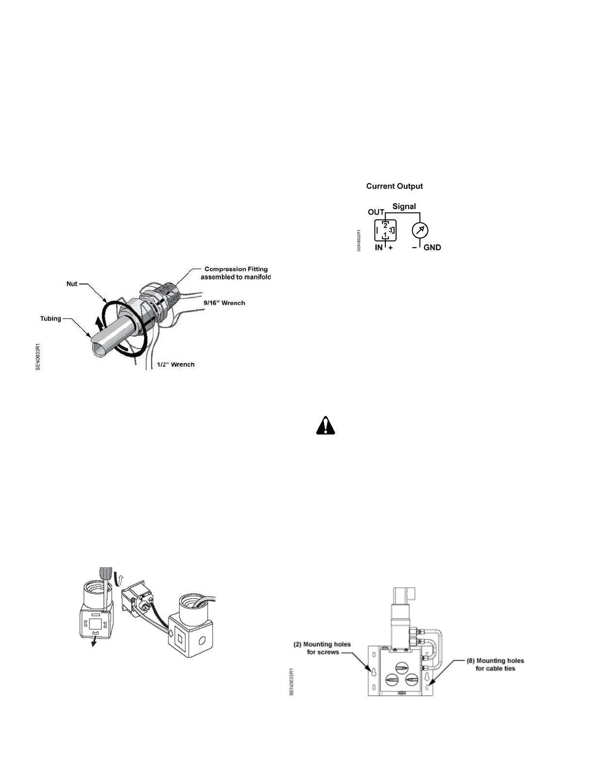
1. Assemble compression fittings to the manifold
finger-tight, and then tighten a minimum 2 to 3
turns with 5/8” wrench or to a maximum 25 ft-lbs
(34 Nm). See Figure 2.
2. Insert the HIGH and LOW pressure lines into the
appropriate pressure port compression fittings at
the bottom of the manifold. Be sure to fully insert
the pressure lines against the inside shoulder and
finger-tighten the nut.
3. While holding the fitting body with the 9/16”
wrench, tighten the nut 1-1/4 turn with the 1/2”
wrench.
Figure 2. Attaching Compression Lines to the
Compression Fittings.
4. Pressurize the system, and then:
a. Slowly open valves V1 and V2.
b. Close valve V3.
Wiring
1. Use a Phillips or flat-blade screwdriver to
completely remove the mounting screw from
conduit cap.
2. Use a flat-blade screwdriver to pry up the
termination board where indicated. (LIFT is
embossed on the cover.) See Figure 3.
SEN0631R1
Figure 3. Accessing and Connecting to the
Wiring Terminals.
3. Feed wiring through the conduit cap and
terminate wires as shown.
NOTE: For non-conduit installations, insert the
plastic connection with washer from the
Non-conduit Assembly Kit before
terminating wires.
Terminal
1 (IN) Operating voltage 7.5 to 33 Vdc
2 (OUT) Output signal 4 to 20 mA
3 Not used
Figure 4. Wiring Terminals, Sensor Top View.
4. Snap the termination board back into the conduit
cap.
NOTE: The termination board can be oriented in
any direction.
5. Remove white, protective cap from sensor.
6. Insert rubber gasket onto sensor's metal leads.
Observe the different slot sizes on the gasket.
CAUTION:
Lead slots in the conduit cap must be
oriented to the sensor's metal leads.
NOTE: The ground lead may appear slightly
bent, but do not attempt to straighten it.
Insert the ground lead into the conduit
cap first to correct any alignment issues.
7. Snap conduit cap onto sensor.
8. Replace and secure with the mounting screw.
Mounting the Sensor/Manifold Assembly
1. Use two screws or required number of nylon tie
wraps to mount the sensor/manifold assembly.
Figure 5. Mounting Options and Approved Position.
Page 2 of 3 Siemens Industry, Inc.
Document No. 129-900
Installation Instructions
June 7, 2012
Mounting the Sensor/Manifold Assembly
(Continued)
2. Ensure that the sensor is mounted vertically. The
conduit cap may be positioned to face left, right,
front or back.
SEN0634R1
Figure 6. Unapproved Mounting Positions.
3. If air bleeding is desired:
a. Carefully loosen the two nuts of the
compression fittings assembled to the sensor.
See Figure 7.
NOTE: While holding the fitting body with the
9/16” wrench, loosen the nuts with the
1/2” wrench.
SEN0638R1
Compression Fitting
Nuts for Bleeding
Figure 7. Compression Fitting Nuts Location.
b. Carefully tighten the nuts after bubble-free
media flows out.
The installation is now complete.
Information in this publication is based on current specifications. The company reserves the right to make changes in specifications and
models as design improvements are introduced. Product or company names mentioned herein may be the trademarks of their respective
owners. © 2012 Siemens Industry, Inc.
Siemens Industry, Inc.
Building Technologies Division
1000 Deerfield Parkway
Buffalo Grove, IL 60089-4513
USA
+1-847-215-1000
Your feedback is important to us. If you have
comments about this document, please send
Document No. 129-900
Printed in the USA
Page 3 of 3
  • Page 1 1
  • Page 2 2
  • Page 3 3

Siemens QBE3190UD25 User manual

Type
User manual

Siemens QBE3190UD25 is a Wet Differential Pressure Sensor with Manifold Assembly that utilizes unique, well-proven ceramic technology, making it ideal for various industries. It features unidirectional flow with a three-valve manifold, enabling precise differential pressure measurement. The sensor offers a pressure rating of 0 to 25 psi and a maximum manifold pressure rating of 250 psi. Its robust design ensures durability and reliability in demanding applications.

Ask a question and I''ll find the answer in the document

Finding information in a document is now easier with AI