Miniware MDP-P905 User manual

Type
User manual

Miniware MDP-P905 is a versatile digital power module designed for precise voltage and current control in various applications. With an intuitive panel interface, users can easily adjust settings, monitor real-time power parameters, and navigate through different display modes. Its key features include:

  • Adjustable voltage and current settings with coarse and fine adjustment modes.
  • Real-time monitoring of voltage, current, and power.
  • Output on/off control and parameter locking for added safety.
  • Rapid voltage and current selection menu for quick parameter changes.
  • Wireless address modification capability via USB for remote control integration.
Before using this product, please read this manual
(This user's manual written based on firmware version V1.20)
MDP-P905
User Manul Of Digital Power Module
table of Contents
Describes the functional
Operation panel interface
2.1 groundwork interface
2.2 the voltage-current adjustment setting screen (when toggle wheel)
2.3 browse display mode
2.4 Settings menu
2.5 Rapid setting voltage and current menu
2.6 Wireless address modification method
The method
Described in
Appendix indicator definitions updates 1
1
2
6
3
4
5
6
3
7
8
9
9
Operation Panel Explains
2
1)
Press to select sub-functions;
coarse enable parameter is set.
2)
Press sub function menu setting change parameter values.
3) RUN / LOCK output / Lock
Deputy Press locking function parameters.
4) Dial
Vice feature to jump to change the menu setting parameter values.
5) Priority key
Keys MENU, and SET low priority roller.
6)Shortcuts: Press SET button and simultaneously press the MENU key is provided into the rapid voltage
and current selection menu,ENCODER using preset switching cycle, the SET select a preset
output interface and switching to the operating state, a timeout without selection or click
Exit Exit MENU, press MENU no operation.
CC / CV
SET
LOCK / CONNECT
<- +>
Dial
Light output terminal
Panel Lights
Figure 1.0
The main function switching voltage and current adjustment item;
Switch the display contents of the main function to check the current settings.
The main function output enable.
Key RUN / LOCK high priority.
The main function to change the value.
MENU
RUN
LOCK
SET Set
MENU menu
3
Each function interface
RUN / LOCK:
1) output on or off operation:
Press (less than 2 seconds), the output on or off, the highest priority. Immediately determined difference between
the current real-time voltage and current provided to the open current voltage if the output is turned on (refer to
the Appendix 1)
2) Parameter lock and unlock methods:
Press more than 2 seconds to lock the trigger parameters, first press flipping only once. SET key lock function can
not operate, voltage and current can not be provided, there is no way to display and control the remote control of
the present power supply.
Note: Each output is not turned on by default, you need to press once before opening.
This roller adjustment term I / U.
A lock display pattern of the locking
Real-time current
Real-time voltage
Real-time power
2.1.1 Open output interface
2.1.2 off the output interface
This roller adjustment term I / U.
Display a lock pattern lock
Status areaON / CC / CV / OFF
Setting current
Setting voltage
Real-time power
Channel number displayed after
the connection is displayed
2.1 Foundation work Interface
Status areaON / CC / CV / OFF
Channel number displayed after
the connection is displayed
4
2.2 the voltage-current adjustment setting screen (when toggle wheel)
2.2.1 Select Set voltage or current Method:
2.2.2 change the settings worth method:
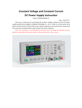
In the non-LOCK state, normal operation when toggle wheel interface, the original display region of the power set value
becomes the display region does not change the real-time voltage and current; LOCK mode change state can not enter the
setting value. No operation 1 second after the wheel, the power set value back to the display.
wheel is U When toggle wheel operating voltage set value, 0.01. ~ 30.000V.
This roller adjustment term I / U.
A lock region display pattern of the
locking
Real-time current
Real-time voltage
Channel number displayed after
the connection is displayed
This roller adjustment term I / U.
A lock region display pattern of the
locking
Real-time current
real-time voltage
Channel number displayed after
the connection is displayed
Voltage and current
settings Numerical
After the toggle wheel
In the non-LOCK state, the main interface SET key press, to modify the "current wheel adjustment item" ( I or U ) .
select U Modify setting voltage value represents; choose I It represents the set current value to modify.
When the setting item to the roller I Time , Toggle wheel operating current setpoint, 0.005A ~ 5.000A;
Status areaON / CC / CV / OFF
Real-time power
Status areaON / CC / CV / OFF
Voltage and current
settings title
2.2.3 How coarse or fine change the values:
Coarse: Long press the SET key, while the toggle trackwheel, a coarse adjustment voltage 0.3V per step, stepping current 30mA.
Fine: when SET key is not pressed, a jog dial, when the voltage step 0.01V, current stepping 1mA.
2.2.4 The factory default setting voltage 3.000V, the default setting current 1.000A.
2.3 Browse menu display
2.3.3 RUN / LOCK key operation does not affect the current display content type and category.
2.3.1 Press the button DISP / MENU Enter browsing mode (Figure1.1), Press again to immediately return to the main
interface;
Page Display menu Status areaON / CC / CV / OFF
Real-time current
Real-time voltage
Display menu information
In the main interface short press DISP / MENU displays basic setting parameters:
1 ) Input voltage Inp Vol
2 ) Input current Inp Cur
3 ) Input current limit Inp Cur
4 ) Machine temperature Temp;
5) version information. as follows:
Figure 1.1
5
2.3.2 Corresponds to the scroll wheel turning (without circulation), view the current status and power settings in the
browser mode 5 seconds-free operation automatically returned to the main interface;
display and control channel
number display is
connected to the after
Display menu title
6
2.4 Setting menu
Press button DISP / MENU enter the setup menu by the SET key, to cycle solid angular position,
ENCODER scrolling menu item pointing triangle "Menuitem";
ENCODER to adjust the setting value triangle pointing to "Value";
Real-time voltage
Real-time current
Displaying a menu page
Channel number displayed after
the connection is displayed
Device ID number
Hardware version number
Software version number
page number
Numerical
adjustment item
Indicates to the title item, indicating
that the menu item is scrolled title
2.5 Rapid setting voltage and current menu
1) Set Menu 1: Input current limit;
2) Set Menu 2: Automatically match the radio address and TX RX Addr, when the wireless address match, if the power output on
the basis of safety, will be forced to shut down the power supply output;
3) Set Menu 3: sound volume adjustment Sound Adjuset.
Press SET button and MENU button to enter the fast selection screen, as shown below;
ENCODER preset value using Cycle
SET button to select a corresponding preset values and switches the output interface to the operating state without selection
or click MENU Exit Exit timeout, no operation press MENU
Solid triangles
status area: ON / CC / CV / OFF
7
The default value can be modified by Q_SET.TXT documents, the contents of the file as shown below, changes take effect after the restart.
File name
Serial number (up to 10) Set voltage (0.01V ~ 30. 000V) Set current (0.005A ~ 5. 000A)
2.6 Wireless address modification method
Power can enter the U disk to modify wireless radio frequency with the address of the file to match the display and control, the document
called RX_ADDR.TXT, the contents of the file as shown below, changes will take effect after reboot.
Wireless Address
file name
Radio frequency
Set Current
Set voltage
serial number
Indicator Definition
A: lamp output terminal (for details see FIG. 1):
Normal full light output, it turns off when the output is off, the output off after 1 minute, go to sleep output off after six minutes,
Quanmie off.
B: panel lights (for details see FIG. 1):
1) When the output is off, the blue light in the upper respiratory state;
2) an output, the constant-voltage-red light when in the state, when a constant current upper full bright light blue;
4) when the alarm (including input overvoltage, overheating, power supply fails, the output to reach its own alarm condition)Red light
flashes up and down at the same time.
State
Bright flame
Often off
Bright flame
Always put out
Always off
Turn off the flash
sparkle
Meaning
Turn off the output
Turn on the output, constant current CV state
Parameter lock
Select the extension has been disconnected
Light-bit
Light output terminal
Red light 1
Blue lights 2
Red light 2
Green light 1
Up and down the red
8
3) when the locking force, the lower side of the red light;
Standby, screen off
Turn on the output
alarm
Turn on the output,state of the constant voltage CC
Turn off the output
Bright flame
Turn off the output
Always put out
Bright flame
Always put out Parameter not locked
sparkle
Bright flame
has been disconnected
not disconnected
Press the power button of the SET, while usb connected to the computer with the USB cable, the computer name will appear: DFU
Vx_xx_x removable hard disk, the Prepared .hex firmware copied to the root directory of the mobile disk, the firmware when the extension
becomes .rdy .hex, power restart, the firmware is completed upgrade.
Upgrade
9
Note that (abnormalities alarm description):
1. If the interface displays "Factory Fail", the default parameter file read exception.
2. If the interface displays "Param Error", the power anomaly reads the parameter file.
3. If the interface displays "Quick Setting Error", the rapid voltage and current provided abnormal parameter files.
4. The input current exceeds the set current value of + 20% of the alarm, the interface displays "INPUT ELEC ERROR", buzzer, double
red flash.
5. The input voltage is lower than 3V alarm, display interface "INPUT VOLT ERROR", buzzer, double flash red.
6. When the device temperature is less than 0 degrees, greater than 70 degrees, it will shut down.
7. When the screen displays "Flash Error", flash chips exception.
8. When the screen displays "Wireless Error", the wireless chip exception.
Appendix 1 Description
  • Page 1 1
  • Page 2 2
  • Page 3 3
  • Page 4 4
  • Page 5 5
  • Page 6 6
  • Page 7 7
  • Page 8 8
  • Page 9 9
  • Page 10 10

Miniware MDP-P905 User manual

Type
User manual

Miniware MDP-P905 is a versatile digital power module designed for precise voltage and current control in various applications. With an intuitive panel interface, users can easily adjust settings, monitor real-time power parameters, and navigate through different display modes. Its key features include:

  • Adjustable voltage and current settings with coarse and fine adjustment modes.
  • Real-time monitoring of voltage, current, and power.
  • Output on/off control and parameter locking for added safety.
  • Rapid voltage and current selection menu for quick parameter changes.
  • Wireless address modification capability via USB for remote control integration.

Ask a question and I''ll find the answer in the document

Finding information in a document is now easier with AI