Page is loading ...

GL800
USER’S MANUAL
MANUAL NO. GL800-UM-152

Introduction
i
Introduction
Thank you for purchasing the GL800 midi LOGGER.
Please read this manual thoroughly before attempting to use your new product to ensure that you use it
correctly and to its full potential.
Notes on Use
Be sure to read all of the following notes before attempting to use the GL800 midi LOGGER.
1. Note on the CE Marking
The GL800 complies with the EN61326 (1997+A1:1998+A2:2001 Class A) standard based on the EMC
directive (89/336/EMC). It also conforms to the EN61010-1 (1993/A2:1995) standard based on the LV
directive (72/73/EEC).
Although the GL800 complies with the above-mentioned standards, be sure to use it correctly in accordance
with the instructions and notes provided in its User's Manual.
Moreover, use of the GL800 by incorrect procedures may result in damage to the GL800 or may invalidate its
safeguards. Please confirm all of its notes regarding use and other related information to ensure correct use.
2. Warning
This is a Class A product according to the EMC directive.
In a domestic environment, this product may cause radio interference or may be affected by radio
interference to the extent that proper measurement cannot be performed.
3. Notes for Safe Operation
(1) Be sure to use the Graphtec-supplied AC adapter. In environments where there is a lot of noise or where
the power supply is unstable, we recommend that you ground the GL800.
(2) When a high-voltage signal cable has been connected to the main unit's analog signal input terminal,
avoid touching the leads of the input terminal's signal cable to prevent electrical shock due to high
voltage.
(3) Ensure that the GL800's power source is positioned so that it can easily be disconnected.
4. Notes on Functions and Performance
(1) Be sure to connect the main unit to an AC or DC power supply that conforms to the rated range.
Connection to a non-rated power supply may cause the main unit to overheat and break down.
(2) Do not block the vent on the main unit.
Continued operation with the vent blocked may cause the main unit to overheat and break down.
(3) To avoid malfunctions and other damage, avoid using the GL800 in the following locations.
• Places exposed to high temperature and/or high humidity, such as in direct sunlight or near heating
equipment. (Operating range - Temperature: 0 to 45°C (15 to 40°C when battery pack is mounted),
Humidity: 5 to 85% RH)
• Locations subject to excessive salt spray or heavy fumes from corrosive gas or solvents.
• Excessively dusty locations.
• Locations subject to strong vibrations or shock.
• Locations subject to surge voltages and/or electromagnetic interference.
(4) If the main unit becomes soiled, wipe it off using a soft, dry cloth. Use of organic solvents (such as
thinner or benzene) causes deterioration and discoloration of the outer casing.

ii
Introduction
(5) Do not use the GL800 in the vicinity of other devices which are susceptible to electromagnetic
interference.
(6) Measured results may not conform to the stated specifications if the GL800 is used in an environment
which is subject to strong electromagnetic interference.
(7) Insofar as possible, position the GL800 input signal cables away from any other cables which are likely
to be affected by electromagnetic interference.
(8) For stabilized measurement, allow the GL800 to warm up for at least 30 minutes after turning it on.

To Ensure Safe and Correct Use
iii
To Ensure Safe and Correct Use
• To ensure safe and correct use of the GL800, read this Manual thoroughly before use.
• After having read this Manual, keep it in a handy location for quick reference as needed.
• Do not permit small children to touch the GL800.
• The following describes important points for safe operation. Please be sure to observe them strictly.
Conventions Used in This Manual
To promote safe and accurate use of the GL800 as well as to prevent human injury and property damage,
safety precautions provided in this manual are ranked into the five categories described below. Be sure you
understand the difference between each of the categories.
DANGER
This category provides information that, if ignored, is highly likely to cause fatal or serious injury to
the operator.
WARNING
This category provides information that, if ignored, is likely to cause fatal or serious injury to the
operator.
CAUTION
This category provides information that, if ignored, could cause physical damage to the GL450.
HIGH TEMPERATURE
This category provides information that, if ignored, is likely to cause burns or other injury to the
operator due to contact with high temperature.
ELECTRICAL SHOCK
This category provides information that, if ignored, is likely to expose the operator to electrical
shock.
Description of Safety Symbols
The
symbol indicates information that requires careful attention (which includes warnings).
The point requiring attention is described by an illustration or text within or next to the
symbol.
The
symbol indicates action that is prohibited. Such prohibited action is described by an
illustration or text within or next to the
symbol.
The
symbol indicates action that must be performed. Such imperative action is described by an
illustration or text within or next to the
symbol.

iv
Safety Precautions
Safety Precautions
WARNING
Be sure to securely connect the GL800's power cord.
• After checking that the Power switch is turned off, connect the power cord's
female plug to the GL800 and then connect its male plug into the electrical
socket.
• Use of the GL800 without the power cord securely plugged into the
electrical socket may result in electrical shock due to current leakage.
• Before running the GL800 using a DC power supply, be sure to ground the
protective ground terminal (
) to avoid electrical shock and fire hazards.
For grounding, use a ground wire with a diameter of at least 0.75 mm
2
.
When using the GL800 in an environment where grounding is not possible,
ensure that the voltage to be measured is no greater than 50 V (DC or
rms).
If the GL800 generates smoke, is too hot, emits a strange odor, or otherwise functions abnormally, turn off
its power and unplug its power cord from the electrical socket.
• Use of the GL800 in such status may result in a fire hazard or electrical
shock.
• After checking that smoke is no longer being generated, contact your sales
representative or nearest Graphtec vendor to request repair.
• Never try to perform repair yourself. Repair work by inexperienced
personnel is extremely dangerous.
Before turning on the GL800, ensure that the electric socket's supply voltage conforms to the GL800's
power rating.
• Use of a different supply voltage may cause damage to the GL800 or a fire
hazard due to electrical shock or current leakage.
Never disassemble or remodel the GL800.
• Such action may cause a fire hazard due to electric shock or current
leakage.
• Contact with a high-voltage component inside the GL800 may cause
electric shock.
• If repair is required, contact your sales representative or nearest Graphtec
vendor.
Avoid using the GL800 in extremely dusty or humid places.
• Such use may cause a fire hazard due to electrical shock or current
leakage.
Securely connect the power cord
Make sure that the socket has a good
protective ground
Use of a different
supply voltage
prohibited
Amateur repair
prohibited
No disassembly
Use prohibited
Watch out for
electrical shock

Safety Precautions
v
Safety Precautions
WARNING
Avoid using the GL800 in places where it may be exposed to water such as bathrooms, locations exposed
to wind and rain, and so on.
Prevent dust or metallic matter from adhering to the power supply connector.
• Adhesion of foreign matter may cause a fire hazard due to electrical shock
or current leakage.
Never use a damaged power cord.
• Use of a damaged cord may result in a fire hazard due to electrical shock.
• If the cord becomes damaged, order a new one to replace it.
Avoid water
Watch out for
electrical shock
Unplug the power
cord from the socket
No foreign matter
Watch out for
electrical shock

vi
Safety Precautions
Safety Precautions
CAUTION
Do not use or store the GL800 in a location exposed to direct sunlight or the direct draft of an air
conditioner or heater.
• Such location may impair the GL800's performance.
Do not place coffee cups or other receptacles containing fluid on the GL800.
• Fluid spilling inside the GL800 may cause a fire hazard due to electrical
shock or current leakage.
Do not use the GL800 in a location subject to excessive mechanical vibration or electrical noise.
• Such location may impair the GL800's performance.
To insert or disconnect the power cord or a signal input cable, grasp the power cord's plug or the signal
input cable's connector.
• Pulling the cord/cable itself damages the cord/cable, resulting in a fire
hazard or electrical shock.
If fluid or foreign matters enters inside the GL800, turn off the Power switch and disconnect the power cord
from the electrical socket.
• Use in such status may cause a fire hazard due to electrical shock or
current leakage.
• Contact your sales representative or nearest Graphtec vendor to request
repair.
Do not input voltage that exceeds the permissible input voltage range that is specified on the GL800's
label.
• Exceeding the specified voltage input range may cause electrical shock or
a fire hazard.
Storage/Use prohibited
Use prohibited
Unplug the power
cord from the socket
No pulling
Use prohibited
Avoid fluids
Watch out for
electrical shock

Safety Precautions
vii
Do not attempt to lubricate the GL800's mechanisms.
• Such action may cause the GL800 to break down.
Never clean the GL800 using a volatile solvent (such as thinner or benzine).
• Such action may impair the GL800's performance.
• Clean off any soiled areas using a soft dry cloth.
Safety Precautions
CAUTION
No lubrication
No volatile solvents

viii
Contents
CONTENTS
Introduction ........................................................................................................................................................ i
To Ensure Safe and Correct Use ..................................................................................................................... iii
Conventions Used in This Manual ......................................................................................................... iii
Description of Safety Symbols ............................................................................................................... iii
Safety Precautions ........................................................................................................................................... iv
General Description ...................................................................................1-1
1.1 Overview ..................................................................................................................................... 1-2
1.2 Features ...................................................................................................................................... 1-2
Input ............................................................................................................................................. 1-2
Display & Operation ..................................................................................................................... 1-2
Data Capture ............................................................................................................................... 1-2
Data Control & Processing .......................................................................................................... 1-2
1.3 Operating Environment ............................................................................................................. 1-3
Ambient Operating Conditions ..................................................................................................... 1-3
Warming-up Before Use .............................................................................................................. 1-3
Configuration When in Use .......................................................................................................... 1-3
1.4 Notes on Temperature Measurement ....................................................................................... 1-4
1.5 Notes on Using the Monitor ...................................................................................................... 1-4
1.6 Changing the Display Language .............................................................................................. 1-4
Checks and Preparation ............................................................................2-1
2.1 Checking the Outer Casing....................................................................................................... 2-2
2.2 Checking the Accessories ........................................................................................................ 2-2
2.3 GL800 Part Names and Functions ........................................................................................... 2-3
2.4 Connecting the Power Cable and Turning on the Power ....................................................... 2-4
Connecting to an AC Power Supply ............................................................................................ 2-4
Connecting to a DC Power Supply .............................................................................................. 2-5
2.5 Connecting the Signal Input Cables ........................................................................................ 2-6
Terminal Configuration and Signal Types .................................................................................... 2-6
Connection diagram .................................................................................................................... 2-6
2.6 Logic Alarm Cable Connection and Functions ....................................................................... 2-7
Circuit Example of Relay Drive by Alarm Output ......................................................................... 2-7
2.7 Attaching USB Memory ............................................................................................................. 2-9
Inserting a USB Memory ............................................................................................................. 2-9
2.8 Connecting to a PC.................................................................................................................. 2-10
Connection Using a USB Cable ................................................................................................ 2-10
LAN Connection ......................................................................................................................... 2-11
2.9 Using the Battery Pack (Option) ............................................................................................ 2-12
Mounting the Battery Pack ........................................................................................................ 2-12
Charging the Battery .................................................................................................................. 2-13
2.10 Connecting the Humidity Sensor (Option) ............................................................................ 2-14
2.11 Mounting and Removing the Terminal Unit ........................................................................... 2-15
To Remove ................................................................................................................................ 2-15
To Mount .................................................................................................................................... 2-16

Contents
ix
2.12 Mounting the Extension Terminal Base Set (B-537) ............................................................. 2-17
B-537 Set Contents ................................................................................................................... 2-17
To Mount .................................................................................................................................... 2-17
2.13 Mounting the 20 Channel Extension Terminal Set (B-538) .................................................. 2-18
B-538 Set Contents ................................................................................................................... 2-18
To Mount .................................................................................................................................... 2-18
2.14 Precautions to Observe When Performing Measurement ................................................... 2-20
2.15 Noise Countermeasures ......................................................................................................... 2-21
2.16 Setting the Date and Time....................................................................................................... 2-22
How to Recharge the Rechargeable Battery ............................................................................. 2-22
How to Set the Date and Time ................................................................................................... 2-22
Settings and Measurement ........................................................................3-1
3.1 Window names and functions .................................................................................................. 3-2
3.2 Key Operation ............................................................................................................................ 3-4
(1) CH GROUP ............................................................................................................................ 3-4
(2) SPAN/TRACE/POSION .......................................................................................................... 3-5
(3) TIME/DIV ................................................................................................................................ 3-5
(4) MENU ..................................................................................................................................... 3-6
(5) QUIT (LOCAL)........................................................................................................................ 3-6
(6) Direction keys ......................................................................................................................... 3-6
(7) ENTER ................................................................................................................................... 3-7
(8) FAST FORWARD key (KEY LOCK) ....................................................................................... 3-7
(9) START/STOP (USB Drive Mode) ........................................................................................... 3-7
(10) REVIEW ............................................................................................................................... 3-8
(11) DISPLAY ............................................................................................................................... 3-9
(12) CURSOR (ALARM CLEAR) ............................................................................................... 3-10
(13) FILE .................................................................................................................................... 3-10
(14) NAVI .................................................................................................................................... 3-11
Basic Procedures Used in Settings ............................................................................................ 3-11
3.3 Operation Modes ..................................................................................................................... 3-12
(1) Free Running ....................................................................................................................... 3-12
(2) Capturing .............................................................................................................................. 3-13
(3) Dual View Replaying ............................................................................................................ 3-13
(4) Replaying ............................................................................................................................. 3-14
3.4 Setting Menus .......................................................................................................................... 3-15
3.5 WEB Server Function .............................................................................................................. 3-38
Specifications .............................................................................................4-1
4.1 Standard Specifications ............................................................................................................ 4-2
Standard Specifications ............................................................................................................... 4-2
Internal memory devices ............................................................................................................. 4-3
PC Interface ................................................................................................................................. 4-3
Monitor ......................................................................................................................................... 4-3
Input Unit Specifications .............................................................................................................. 4-4
4.2 Function Specifications ............................................................................................................ 4-5
Function Specifications ................................................................................................................ 4-5
Trigger Functions ......................................................................................................................... 4-5
External Input/Output Functions .................................................................................................. 4-6

x
Contents
4.3 Accessory/Option Specifications ............................................................................................ 4-7
Control Software .......................................................................................................................... 4-7
Accessories ................................................................................................................................. 4-7
Battery Pack B-517 (Option) ........................................................................................................ 4-7
Humidity Sensor B-530 (Option) .................................................................................................. 4-8
Options ........................................................................................................................................ 4-8
4.4 External Dimensions ................................................................................................................. 4-9
Index .............................................................................................................I-1

This chapter provides a general description of the
GL800 and its features.
CHAPTER
1
General Description
1.1 Overview
1.2 Features
1.3 Operating Environment
1.4 Notes on Temperature Measurement
1.5 Notes on Using the Monitor
1.6 Changing the Display Language

1-2
General Description
1.1 Overview
The GL800 (with color monitor and internal memory) are compact, lightweight, multi-channel data loggers.
GL800 are provided with 20 channels as a standard measurement feature, or can be extended up to 200
channels by attaching additional terminal sets.
GL800 are also equipped with an internal flash memory to store data and enable the direct capture of a large
volume of data to USB memory.
Furthermore, the data loggers are equipped with USB and Ethernet interfaces to a PC to enable system
configurations according to your application.
The Ethernet feature includes WEB and FTP server functions which allow monitoring from a remote location
and data transfer.
1.2 Features
Input
(1) Adoption of a pluggable M3 screw type input terminal facilitates wiring.
(2) The GL800 is provided with 20 channels as a standard measurement feature, or can be
extended up to 200 channels by attaching additional terminal sets.
(3) All channels are isolated, enabling measurement of signals of different references.
Display & Operation
(1) With the GL800's 5.7-inch TFT color liquid crystal display, you can confirm the waveforms of
measured data and each channel's settings at a glance.
(2) Easy operation is achieved through a straightforward menu structure and key allocation which
resembles mobile phones.
Data Capture
(1) Data can be directly captured and maintained in the internal or USB memory.
(2) Internal memory used for the built-in memory maintains captured data even after the power is
turned off.
(3) The Internal memory can be used with disk images thus multiple data items can be
maintained.
Data Control & Processing
(1) The application software provided lets you set conditions and monitor data on a PC.
(2) The USB drive mode function enables the GL800's internal memory to be recognized as an
external drive by your PC. (Connect the GL800 to your PC and turn on the power supply to the
GL800 while holding down the [START] key.)
(3) Captured data can be read from the application software to files and displayed for processing.
(4) Data can be transferred off-line to a computer using USB memory.
(5) The WEB server function enables control and monitoring from a remote location without using
dedicated software.
(6) The FTP server function enables handling internal memory and USB memory data from a PC.

General Description
1-3
1.3 Operating Environment
This section explains the operating environment for the GL800.
Ambient Operating Conditions
(1) Ambient temperature and humidity (the GL800 must be operated within the following ranges.)
• Temperature range: 0 to 45°C (15 to 40°C when battery pack is mounted)
• Humidity range: 5 to 85% RH
(2) Environment (do not use in the following locations.)
• A Location such as being exposed to direct sunlight
• Locations exposed to salty air, corrosive gases, or organic solvents
• Dusty locations
• Locations subject to vibration or impact
• Locations subject to voltage surge or electromagnetic interference such as lightning or
electric furnaces
(3) Installation category (over-voltage category)
• The GL800 conforms to the IEC664 installation category
CHECKPOINT
If condensation occurs...
Condensation occurs in the form of water droplets on the device surfaces and interior when the GL800
is moved from a cold to a warm location. Using the GL800 with condensation will cause malfunctioning.
Wait until the condensation has disappeared before turning on the power.
Warming-up Before Use
The GL800 should be allowed to warm up with the power turned on for approximately 30 minutes
to ensure that it operates according to the specified performance.
Configuration When in Use
Do not use the GL800 standing upright or at an angle. It must always be laid flat.
Usage Configuration
CAUTION
Do not block the air vent on the GL800, as this will cause malfunctioning.
Measurement accuracy may not be satisfactory if the system is used in a condition other than
described above.

1-4
General Description
1.4 Notes on Temperature Measurement
Please observe the following precautions when performing temperature measurement.
(1) Do not block the air vents. Always provide a space of at least 30 cm on all sides of the GL800.
(2) For stabilized temperature measurement, allow the GL800 to warm up for at least 30 minutes
after turning it on.
(3) Exposure of the input terminals to direct drafts, direct sunlight, or abrupt changes in
temperature may impair the equilibrium of the input parts and result in measurement errors. To
measure temperature in such an environment, take appropriate countermeasures such as
changing the installation site of the GL800.
(4) To conduct measurement in noisy environments, connect the GL800’s GND terminal to ground
(refer to page 2-21).
(5) If measured values fluctuate due to noise, set to a slower sampling speed (refer to page 3-20).
1.5 Notes on Using the Monitor
The monitor is an LCD display unit, and so the display will vary depending on the operating environment.
CHECKPOINT
If the screen saver function is used, it will operate and clear the screen if no operations are performed
during the preset time. If the screen saver operates, press any key to restore the display.
CAUTION
• Condensation may form on the LCD screen if the GL800 is moved from a cold to a warm location. If
this occurs, wait until the LCD screen warms up to room temperature.
• The LCD screen is manufactured to extremely high precision. Black dots may appear, or red, blue,
and green dots may not disappear. Likewise, streaks may appear when viewed from certain angles.
These phenomena are due to the LCD screen construction, and are not signs of a fault.
1.6 Changing the Display Language
You can choose the language displayed on the screen. The default display language is set to English when
the GL800 is shipped overseas. To change the display language, see the instructions in "OTHR:Language".

This chapter explains how to check the GL800's external casing and
accessories, and how to prepare the GL800 for operation.
CHAPTER
2
Checks and Preparation
2.1 Checking the Outer Casing
2.2 Checking the Accessories
2.3 GL800 Part Names and Functions
2.4 Connecting the Power Cable and Turning on the Power
2.5 Connecting the Signal Input Cables
2.6 Logic Alarm Cable Connection and Functions
2.7 Attaching USB Memory
2.8 Connecting to a PC
2.9 Using the Battery Pack (Option)
2.10 Connecting the Humidity Sensor (Option)
2.11 Mounting and Removing the Terminal Unit
2.12 Mounting the Extension Terminal Base Set (B-537)
2.13 Mounting the 20 Channel Extension Terminal Set (B-538)
2.14 Precautions to Observe When Performing Measurement
2.15 Noise Countermeasures
2.16 Setting the Date and Time

2-2
Checks and Preparation
2.1 Checking the Outer Casing
After unpacking, check the GL800's outer casing before use. In particular, please check for the following:
• Surface scratches
• Other flaws such as stains or dirt
2.2 Checking the Accessories
After unpacking, check that the following standard accessories are included.
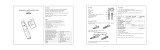
Standard Accessories
Optional Accessories
Item Remarks Quantity
Quick Start Guide GL800-UM-85x 1
CD-ROM User's Manual, Application software 1
AC cable/AC adapter 100 to 240 VAC, 50/60 Hz 1
Item Option No. Remarks
Battery pack B-517 7.2V/2200mAh
DC drive cable B-514 2 m, Bare tips
Humidity sensor B-530 3-m length with dedicated power connector
Extension terminal base set B-537 Extension terminal base unit, cable
20 channel extension terminal set B-538 20 channel terminals, extension terminal base unit,
connection plate, screws
Logic alarm cable B-513 2 m, Bare tips
T-type thermocouple JBS-7115-5M-T 5-m length, 4 thermocouples per set
K-type thermocouple JBS-7115-5M-K 5-m length, 4 thermocouples per set
K-type thermocouple RIC-410 1.1m
(needle type probes)
K-type thermocouple RIC-420 1.1m
(stationary surface probes)
K-type thermocouple RIC-430 1.1m
(stationary surface L probes)

Checks and Preparation
2-3
2.3 GL800 Part Names and Functions
This section describes the names and function of parts of the GL800.
PC interface terminals
USB
LAN
Monitor
Power switch
Operation status LED
POWER : ON when the power is ON
START : ON during data capture
CHARGE : ON while the battery is charging
Control panel keys
AC adapter jack
External input/output terminal
LOGIC/PULSE : LOGIC/PULSE input
EXT TRIG : Trigger input
ALARM : Alarm output
Power jack for the humidity sensor
GND terminal
Analog signal input terminals
USB memory terminal
Battery cover
Contains battery pack (B-517) sold separately
Model imprint and others

2-4
Checks and Preparation
2.4
Connecting the Power Cable and Turning on the Power
This section describes how to connect the power cable and turn on the power. The connection method will
vary depending on the type of power supply used.
Connecting to an AC Power Supply
Use the AC cable and AC adapter that are provided as accessories.
CAUTION
Be sure to use the AC adapter that is supplied as a standard accessory.
(1) Plug the AC cable into the AC adapter.
(2) Connect the output side of the AC adapter to the connector on the GL800.
(3) Using the flat-blade screwdriver, press against the minus (-) button above the GND terminal,
while connecting the grounding cable to the GL800. Connect the other end of the cable to
ground.
(4) Plug the AC cable into the mains power outlet.
(5) Press the power switch on the GL800 to the ON side to turn on the power.
CAUTION
Always connect the GND terminal and refer to the safety precautions. The GL800 must be grounded
even when connected to other devices and sharing a common ground level.
AC adapter
AC cable
AC adapter cable

Checks and Preparation
2-5
Connecting to a DC Power Supply
Use the optional DC drive cable (B-514).
CAUTION
Use a power supply within the 8.5 to 24 VDC range.
(1) Configure the tip of the DC drive cable (B-514: 2m) to enable it to be connected to the DC
power supply.
(2) Connect the DC output side to the power supply connector on the GL800.
DC drive cable
(B-514)
White (+ side)
Shielded lead (- side)
(3) Connect the DC input side to the DC power supply.
CAUTION
Be sure to check the polarity of the wire tips when performing wiring.
(4) Press the power switch on the GL800 to the ON side to turn on the power.
/