Page is loading ...

E2000 D PRINTED IN U.S.A.
&
(419) 636-4242
D
F
AX (419) 633-1674
INGERSOLL-RAND COMPANY
P.O. BOX 151 D ONE ARO CENTER D BRYAN, OHIO 43506Ć0151
OPERATOR’S
MANUAL
650556-1
INCLUDING: OPERATION, INSTALLATION & MAINTENANCE
AIRLESS
SPRA
Y PUMP SYSTEM - CART MOUNTED
650556-1
INCLUDE MANUALS: 66302ĆX LOWER PUMP END (PN 97999Ć648), 650685ĆX PUMP (97999Ć657), 65142XĆX
FILTER (97999Ć6), P292X1ĆXXX PIGGYBACK (PN 100400Ć8) & GENERAL INFORMATION SĆ636 (97999Ć636)
READ THIS MANUAL CAREFULL
Y BEFORE INST
ALLING,
OPERA
TING OR SER
VICING THIS EQUIPMENT
.
6” STAINLESS STEEL, TWO BALL PUMP, 60:1 RATIO
RELEASED: 12-11-98
REVISED: 11-16-00
(REV.
B)
SERVICE KITS
• Use only genuine AROR replacement parts to assure compatible
pressure rating and longest service life.
• 61355 for repair of Air Motor section.
Service Note: The Air Motor Service / Parts Manual is not shipped
with the pump but it is included with each Service Kit. If this Service
/ Parts Information is needed, request the Air Motor Operator's
Manual from ARO. (Manual 6564XĆX, PNĂ97999Ć174).
• 637307ĆāP43 for repair of Lower Pump section.
PUMP
SYSTEM DA
TA
Model 650556Ć1...................
Pump System Type Cart Mounted Portable,.........
Air Operated, Two Ball S'Steel
Pump Model 650685ĆP43..............
Ratio 60:1....................
Air Inlet 1/2"Ć14 N.P.T.F.Ć1 (female)................
Air Exhaust Muffler included.............
Material Inlet Suction Tube.............
Dimensional Data See page 3.........
Air Motor 65665ĆB.................
Motor Repair Kit 61355..........
Lower Pump End 66302ĆāP43...........
Lower Pump Repair Kit 637307āĆP43....
Weight (less carton) 111 Lbs (50 Kgs).......
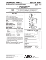
PERFORMANCE
Air Inlet Pressure Range 30Ć100 p.s.i. (2Ć6.9 bar).....
Fluid Pressure Range 1800Ć6000 p.s.i. (124Ć414 bar).......
Max. Rec'd Cycles / Minute 60...
Displacement In
3
Per Cycle 5.5...
Volume / Cycle 3 oz. (90 ml)............
Cycles Per Gallon 41.9..........
Flow @ 60 Cycles / Minute 1.4 g.p.m. (5.4 lpm)...
Noise Level @ 60 Psi Ć 40 Cpm 84.8 db(A) *
* The pump sound pressure level has been updated to an Equivalent Continuous Sound Level (L
Aeq
)to
meet the intent of ANSI S1. 13Ć1971, CAGIĆPNEUROP S5.1 using four microphone locations.
FIGURE 1
Inlet Air Regulator and Material Outlet ManIfold are not shown, see Fig. 2
IMPORTANT This is one of the six documents which support
the system. Replacement copies of these forms are available
upon request.
- 66302ĆX LOWER PUMP END OPERATOR'S MANUAL
(97999Ć648)
= 650556Ć1 PUMP SYSTEM MANUAL (97999Ć840)
- 650685ĆX PUMP MODEL OPERATOR'S MANUAL (97999Ć657)
- P292X1ĆāXXX PIGGYBACK OPERATOR'S MANUAL (100400Ć8)
- 65142XĆX MATERIAL FILTER (97999Ć6)
- GENERAL INFORMATION MANUAL SĆ636 (97999Ć636)

PAGE2OF4
650556Ć1
PARTS LIST / 650556-1
ITEM DESCRIPTION (Size in Inches)
QTY
PART NO. ITEM DESCRIPTION (Size In Inches)
QTY
PART NO.
1 Two Ball Piston Pump (1) 650685ĆP43
2 Cart Assembly (Includes Items 3 thru 14) (1) 67139
3 Cotter Pin (3/32") (2) Y15Ć35ĆC
4 Washer (4) 91522
5 Tip (2) 91011
6 Washer (3/8") (6) Y13Ć6ĆC
7 Screw (3/8" Ć 16 x 1Ć1/4") (4) Y6Ć66ĆC
8 Nut (3/8" Ć 16) (4) Y12Ć6ĆC
9 Wheel Assembly (2) 91515
10 Brace (1) 95102
11 Screw (5/16" Ć 18 x 3/4") (4) Y6Ć53ĆC
12 Nut (5/16" Ć 18) (4) Y12Ć5ĆC
13 Washer (5/16") (4) Y14Ć516ĆC
14 Cart Welding Assembly (1) 67138
15 MaterialFilter (Includes Item 16) (1) 651422Ć70
16 Plug (3/8") (1) Y17Ć13ĆS
17 Muffler (1) 91790ĆZZ
j 18 3/4" Suction Hose Assembly (1) 622606Ć5
j 19 90_ Elbow (3/4") (1) Y43Ć15ĆS
j 20 Suction Tube (5 Gallon) (1) 94263Ć1
21 Hose Assembly (1) 628092ĆF
22 Gauge (1) 100067
23 Modular Piggyback Filter/Regulator (1) P29241Ć100
24 Nipple (1/2" x 1Ć1/2" (m)) (1) Y27Ć54ĆC
25 Bushing (1/2" Ć 14 (m) x 1/4" Ć 18 (f)) (1) 94271
26 Nipple (1/4" Ć 18 (m)) (2) 1950
27 Street Tee (1/4" Ć 18) (1) 94270
28 Needle Valve (1) 94269
29 Adapter (1" (m) x 1/2" (f)) (1) 94256
30 90_ Adapter (1" (m) x 1/4" (f) x 3/4" (f)) (1) 94254
31 Plug (1) Y17Ć11ĆS
j Parts included in 67140Ć1 Asm (std)
Available: 67140Ć2 Asm. uses 94263Ć2 (36" Inlet Tube)
OPERATING INSTRUCTIONS
WARNING
DO NOT EXCEED MAXIMUM OPERATING PRESĆ
SURE OF 6000 P.S.I. (414 BAR) AT 100 P.S.I. (6.9 BAR) AIR INĆ
LET PRESSURE.
WARNING
REFER TO THE PUMP MANUAL FOR ADDITIONĆ
AL OPERATING AND SAFETY PRECAUTIONS AND OTHER
IMPORTANT INFORMATION.
INSTALLATION
OPERATING INSTRUCTIONS / INITIAL SETUP PROCEDURE
This unit comes assembled except for the air supply hose, gun and maĆ
terial hose which must be attached.
• A connector, coupler and air supply hose and must be supplied
to the air regulator.
• Attach a Ground wire to a suitable ground and the Ground Lug
provided on the pump Air Motor.
• Keep containers covered to prevent contamination.
1. Turn the knob on the air regulator counterĆclockwise to zero p.s.i.
2. Attach hose and gun. Place pump inlet tube into a full container of
material.
3. Start the pump to cycle by turning the air regulator knob clockwise.
The pump will cycle several strokes until pressure is built up in the
system, at which time it will stall, check for any loose fittings or leakĆ
age. Check all connections and reĆtighten as necessary.
4. Relief Valve (28) is used to relieve pressure in the hose in order to
change spray tips. Open the relief valve to relieve pressure. Close
the relief valve to continue spray operation.

PAGE3OF4650556Ć1
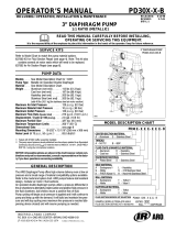
PARTS LIST / 650556-1
AIR INLET
FLUID OUTLET
18
19
20
4
17
21
5
6
22
23
24
7
6
25
27
28
16
29
31
9
30
VIEW A VIEW B
3
VIEW A
VIEW B
VIEW C
VIEW D
VIEW C
VIEW D
25Ć9/16
44Ć31/32
26Ć15/16
26
26
8
10
11
12
13
14
1
15
2
FIGURE 2

PN 97999Ć840
PAGE4OF4
650556Ć1
/