Page is loading ...

Published by MW 0265 Service PaCE Printed in the Netherlands Subject to modification EN 3122 785 12310
©
Copyright 2002 Philips Consumer Electronics B.V. Eindhoven, The Netherlands.
All rights reserved. No part of this publication may be reproduced, stored in a
retrieval system or transmitted, in any form or by any means, electronic,
mechanical, photocopying, or otherwise without the prior permission of Philips.
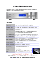
DVD-Video Player DVD763SA
DVD763SA /001 /021 /051
Contents Page
1 Technical Specs and Connection Facilities 2
2 Safety Instructions, Warnings, Notes, and Service
Hints 3
3 Directions for Use 5
4 Mechanical- and Dismantling Instructions 20
5 Diagnostic Software, Trouble Shooting and Test
Instructions 22
6 Block-, Wiring Diagram and Testpoint Overview
Block Diagram 43
Wiring Diagram 44
Testpoint Overview AV Board 45
7 Electrical Diagrams and Print-Layouts Diagram PWB
Power Supply Unit 46
AV Board: SYS Clk & Control (Diagram A1) 47 51-56
AV Board: Video DAC (Diagram A2) 48 51-56
AV Board: Audio (Diagram A3) 49 51-56
AV Board: Video (Diagram A4) 50 51-56
Front Board: Display (Diagram D) 57 58-60
Front Board: Standby (Diagram S) 61 61
Switching Panel (Diagram S1) 62 64-66
SCART Panel (Diagram S2) 63 64-66
8 Alignments(Not Applicable) 67
9 Circuit Descriptions 67
List of Abbreviations 75
IC Data 76
10 Spare Parts List 77

Technical Specifications and Connection Facilities
EN 2 DVD763SA1.
1. Technical Specifications and Connection Facilities
PLAYBACK SYSTEM
DVD Video
SACD multi channel and SACD stereo
Video CD & SVCD
CD (CD-Recordable and CD-Rewritable)
MP3 CD
TV STANDARD (PAL/50Hz) (NTSC/60Hz)
Number of lines 625 525
Playback Multistandard (PAL/NTSC)
VIDEO PERFORMANCE
RGB (SCART) output 0.7 Vpp into 75 ohm
YUV output Y: 1Vpp into 75 ohm
Pr/Cr Pb/Cb: 0.7Vpp into 75 ohm
S-Video output Y: 1Vpp into 75 ohm
C: 0.3Vpp into 75 ohm
Video output 1 Vpp into 75 ohm
Black Level Shift On/Off
Video Shift Left/Right
AUDIO FORMAT
DSD Multichannel and Stereo
MPEG/ Compressed Digital
Dolby Digital 16, 20, 24 bits
DTS/PCM fs, 44.1, 48, 96 kHz
MP3 96, 112, 128, 256 kbps and
(ISO 9660) variable bit rate fs 32, 44.1, 48kHz
Full decoding of Dolby Digital and DTS multi channel sound
Analogue Stereo Sound
Dolby Surround-compatible downmix from Dolby Digital
multi-channel sound
3D Sound for virtual 5.1 channel sound on 2 speakers
SACD AUDIO PERFORMANCE
D/A Converter DSD
SACD fs 2.8224MHz DC - 100kHz
Max. output voltage (0dB) 2V rms
Channel unbalance <0.5 dB
Cut-off frequency 50kHz (Front)
40kHz (Surround, Center,
Subwoofer)
Signal-Noise (1kHz) 105 dB
Dynamic Range (1kHz) 105 dB
Crosstalk (1kHz) 105 dB
Total Harmonic Distortion (1kHz) 97 dB
AUDIO PERFORMANCE (TYPICAL)
DA Converter 24 bits
DVD fs 96 kHz 4 Hz - 44 kHz
CD/Video CD fs 44.1 kHz 4 Hz - 20 kHz
S-Video CD fs 48 kHz 4 Hz - 22 kHz
fs 44.1 kHz 4 Hz - 20 kHz
Signal-Noise (1kHz) 100 dB
Dynamic Range (1kHz) 100 dB
Crosstalk (1kHz) 105 dB
Total Harmonic Distortion (1kHz) 97 dB
MPEG MP3 MPEG Audio L3
CONNECTIONS
SCART 2x Euroconnector
Y Pb/Cb Pr/Cr (480i) Cinch 3x (green, blue, red)
S-Video Output Mini DIN, 4 pins
Video Output 2x Cinch (yellow)
Audio L+R output Cinch (white/red)
Digital Output 1 coaxial, 1 optical
IEC958 for CDDA / LPCM
IEC1937 for MPEG1/2, Dolby
Digital, DTS
6 channel analog output
Audio Front L/R Cinch (white/red)
Audio Surround L/R Cinch (white/red)
Audio Centre Cinch (blue)
Audio Subwoofer Cinch (black)
CABINET
Dimensions (w x h x d) 435 x 77.5 x 303.5 mm
Weight Approximately 3.1 Kg
POWER SUPPLY (UNIVERSAL)
Power inlet 110V-240V, 50/60Hz
Power usage Approx. 23W
Power usage standby < 1W
* typical playing time for movie with 2 spoken languages and
3 subtitle languages
Specifications subject to change without prior notice
Specifications
CL 26532053_048.pdf
150502

Safety Instructions, Warnings and Notes
EN 3DVD763SA 2.
2. Safety Instructions, Warnings and Notes
2.1 Safety Instructions
2.1.1 General Safety
Safety regulations require that during a repair:
• Connect the unit to the mains via an isolation transformer.
• Replace safety components, indicated by the symbol ,
only by components identical to the original ones. Any
other component substitution (other than original type) may
increase risk of fire or electrical shock hazard.
Safety regulations require that after a repair, you must return
the unit in its original condition. Pay, in particular, attention to
the following points:
• Route the wires/cables correctly, and fix them with the
mounted cable clamps.
• Check the insulation of the mains lead for external
damage.
• Check the electrical DC resistance between the mains plug
and the secondary side:
1. Unplug the mains cord, and connect a wire between
the two pins of the mains plug.
2. Set the mains switch to the 'on' position (keep the
mains cord unplugged!).
3. Measure the resistance value between the mains plug
and the front panel, controls, and chassis bottom.
4. Repair or correct unit when the resistance
measurement is less than 1 MΩ.
5. Verify this, before you return the unit to the customer/
user (ref. UL-standard no. 1492).
6. Switch the unit ‘off’, and remove the wire between the
two pins of the mains plug.
2.1.2 Laser Safety
This unit employs a laser. Only qualified service personnel may
remove the cover, or attempt to service this device (due to
possible eye injury).
Laser Device Unit
Type : Semiconductor laser
GaAlAs
Wavelength : 650 nm (DVD)
: 780 nm (VCD/CD)
Output Power : 20 mW (DVD+RW
writing)
: 0.8 mW (DVD
reading)
: 0.3 mW (VCD/CD
reading)
Beam divergence : 60 degree
Figure 2-1 Class 1 Laser Product
Note: Use of controls or adjustments or performance of
procedure other than those specified herein, may result in
hazardous radiation exposure. Avoid direct exposure to beam.
2.2 Warnings
2.2.1 General
• All ICs and many other semiconductors are susceptible to
electrostatic discharges (ESD, symbol "). Careless
handling during repair can reduce life drastically. Make
sure that, during repair, you are at the same potential as
the mass of the set by a wristband with resistance. Keep
components and tools at this same potential. Available
ESD protection equipment:
– Complete kit ESD3 (small tablemat, wristband,
connection box, extension cable and earth cable) 4822
310 10671.
– Wristband tester 4822 344 13999.
• Be careful during measurements in the live voltage section.
The primary side of the power supply (pos. 1005), including
the heatsink, carries live mains voltage when you connect
the player to the mains (even when the player is 'off'!). It is
possible to touch copper tracks and/or components in this
unshielded primary area, when you service the player.
Service personnel must take precautions to prevent
touching this area or components in this area. A 'lightning
stroke' and a stripe-marked printing on the printed wiring
board, indicate the primary side of the power supply.
• Never replace modules, or components, while the unit is
‘on’.
2.2.2 Laser
• The use of optical instruments with this product, will
increase eye hazard.
• Only qualified service personnel may remove the cover or
attempt to service this device, due to possible eye injury.
• Repair handling should take place as much as possible
with a disc loaded inside the player.
• Text below is placed inside the unit, on the laser cover
shield:
Figure 2-2 Warning text
2.2.3 Notes
Dolby
Manufactered under licence from Dolby Laboratories. “Dolby”,
“Pro Logic” and the double-D symbol are trademarks of Dolby
Laboratories. Confidential Unpublished Works. ©1992-1997
Dolby Laboratories, Inc. All rights reserved.
Figure 2-3
Trusurround
TRUSURROUND, SRS and symbol (fig 2-4) are trademarks of
SRS Labs, Inc. TRUSURROUND technology is manufactured
under licence frm SRS labs, Inc.
Figure 2-4
CAUTION VISIBLE AND INVISIBLE LASER RADIATI ON WHEN OPEN AVOID EXPOSURE TO BEAM
ADVARSEL SYNLIG OG USYNLIG LASERSTRÅLING VED ÅBNING UNDGÅ UDSÆTTELSE FOR STRÅLING
ADVARSEL SYNLIG OG USYNLIG LASERSTRÅLING NÅR DEKSEL ÅPNES UNNGÅ EKSPONERING FOR STRÅLEN
VARNING SYNLIG OCH OSYNLIG LASERSTRÅLNING NÄR DENNA DEL ÄR ÖPPNAD BETRAKTA EJ STRÅLEN
VARO! AVATT AESSA OLET ALTTIINA NÄKYVÄLLE JA NÄKYMÄTT ÖMÄLLE LASER SÄTEILYLLE. ÄLÄ KAT SO SÄTEESEEN
VORSICHT SICHTBARE UND UNSICHTBARE LASERSTRAHLUNG WENN ABDECKUNG GEÖFFNET NICHT DEM STRAHL AUSSETSEN
DANGER VISIBLE AND INVISIBLE LASER RADIATI ON WHEN OPEN AVOID DIRECT EXPOSURE TO BEAM
AT TENTION RAYO NNEMENT LASER VISIBLE ET INVISIBLE EN CAS D'OUVERTURE EXPOSITION DANGEREUSE AU FAISCEAU
!

Safety Instructions, Warnings and Notes
EN 4 DVD763SA2.
2.3 Service Hints
2.3.1 Switched Mode Power Supply
The power supply unit has to be replaced in case of failure. The
schematic provided in the manual is only for information and no
service parts will be available.
2.3.2 DVD Module
This module can be repaired as follows:
1. The VAL6011/14 is a combination of loading mechanism
and DVD-mechanism. Both are not repairable units and in
case of failure, it has to be replaced with a new loader
VAL6011/14.
Note: When replacing with a new VAL6011/14, two solder
joints have to be removed after connecting the OPU flex foil
to the mono board.
The solder joints, which shortcircuits the laser diodes to
ground, are for protection against ESD. Refer to figures 2-
5 and 2-6 for location of solder joints.
2. The mono board has to be repaired down to component
level. Repair handling of the monoboard requires a
workshop with sophisticated desoldering tools.
Figure 2-5 Solder joints
Figure 2-6 Solder joints
2.3.3 ComPair
For assistance with the repair process of the monoboard an
electronic fault finding guidance has been developed. This
program is called ComPair.
This ComPair program is available on CDROM.
The version of the CDROM for repair of the monoboard is V1.3
or higher and can be ordered with codenumber 4822 727
21637. This is an update CDROM, so when the ComPair
CDROM is used for the first time, one has to install the ComPair
Engine CDROM V1.2 first.
The V1.2 CDROM can be ordered with code number 4822 727
21634 and has to registered after instalation. The procedure for
registration is explained in the help file of the program and in
the CDROM booklet.
The cable to connect the monoboard with a PC can be ordered
with codenumber: 3122 785 90017.
All the hardware and software requirements of the systems,
necessary for working with ComPair, are described on the
CDROM.
2.3.4 Service Positions
Refer to dismantling instructions for dismounting of the board.
Figures 2-7 to 2-8 shows the service position that are
recommended during repair of the boards.
Figure 2-7 SD4.00SA_CH module
Figure 2-8 DVD763SA model

Mechanical- and Dismantling Instructions
EN 20 DVD763SA4.
4. Mechanical- and Dismantling Instructions
Dismantling Instructions
DISMANTLING INSTRUCTIONS
See exploded view of DVD763SA for item numbers
Mounting
Dismounting
A/V board 1001
Remove Double Scart board
(Only for DVD763SA /EU)
Remove flex and cable
connections.
Remove 7 screws 275
(skt cinch ,optical to back-
plate) and screw 280.
(S-video to back-plate)
Release 2 spacer locking.
Dismount board.
Front Standby board
Remove cable connection.
Remove 2 screws 110.
(Board to Front cabinet)
Dismount board.
Front Display board 1002
Remove cable connections.
Remove the navigation
button 120.
Remove 6 screws 100.
(Board to Front cabinet)
Dismount board.
Front cabinet 001
Remove cable connections.
Open Tray (see instruction below).
Unlock Tray cover 095 and
close tray.
Unlock Front panel from frame by
releasing successively 4 snaps.
(2 on the side and 2 on the bottom )
Place Front panel in front of
the set ( service position ).
TopCover 300
Remove 4 screws 310 and
3 screws 305.
Lift cover from rearside to
remove.
DVD Module 145
Remove flex connections
to A/V board.
Open tray (see instruction below).
Unlock Tray cover 095.
Remove 4 screws 185.
(Loader to bottom bracket)
Remove 2 screws 200.
(Monoboard to bottom bracket )
Close tray.
Lift module up slightly and move
backward to remove.
Power supply unit 1005
Remove cable connections.
Remove 2 screws 190.
(Board to bottom frame)
Release 2 spacer locking.
(Board to bottom frame)
Dismount board.
DVD Monoboard
Remove flex and cable
connections from DVD
Loader to Monoboard.
Remove 4 screws 10 to 13.
(Monoboard to Loader,VAL6011/14)
Dismount Monoboard.
Double Scart board 1003
(Only for DVD763SA /EU)
Remove flex connection to
conn 1300 on scart board.
Remove 4 screws 290.
(scart to back-plate)
Dismount board.
CL 26532053_051.eps
170502
Manually opening of tray
When it is not possible to open the tray with the EJECT button,
the tray can be manually opened.
When no disc is loaded, unlock the tray by moving the slide from left
to right and pull tray outwards.
When a disc is loaded, unlock the tray by pushing the slide inwards with
a screwdriver and pull tray outwards.
Remove 4 screws to remove loader.


Diagnostic Software, Trouble Shooting and Test Instructions
EN 22 DVD763SA5.
5. Diagnostic Software, Trouble Shooting and Test Instructions
5.1 Dealerscript
5.1.1 Purpose of Dealer Script
The dealer script can give a diagnosis on a standalone DVD
player, no other equipment is needed to perform a number of
hardware tests to check if the DVD player is faulty. The
diagnosis is simply a "error" or "pass" message. No indication
is given of faulty hardware modules. Only tests within the scope
of the diagnostic software will be executed hence only faults
within this scope can be detected.
5.1.2 Contents of Dealer Script
The dealer script executes all diagnostic nuclei that do not
need any user interaction and are meaningful on a standalone
DVD player.
The nuclei called in the dealer script are the following (the
number after each nucleus name corresponds with the number
being on the local display when the nucleus is executed during
the dealer script):
Nucleus
Figure 5-1 Dealer script nuclei
Figure 5-2 Dealer Script
Display Nucleus Nucleus Description
Countdown Number Name
7 6 PapChksFl Calculate and verify checksum of FLASH memory
6 12 PapI2cDisp
Checks the I2C interface with the slave processor on
the display board
5 13 PapS2bEcho Checks the I2C interface to the basic engine
4 11 PapI2cNvram Checks the I2C interface with the NVRAM
3 15 PapNvramWrR Pattern test of all locations in the NVRAM
2 16 CompSdramWrR Pattern test of all locations in the SDRAM(s)
1 63 FURORERSdramWrRLow Pattern test of all locations in the SDRAM(s)
Press 2 keys simultaneously
<OPEN/CLOSE> + <PLAY>
Connect to mains.
During the test, the following display
is shown: the counter counts down
from the number of nuclei to be run
before the test finishes. Example:
SET O.K.?
YES
NO
To exit DEALER SCRIPT, disconnect from mains
CL 26532053_053.eps
150502

Diagnostic Software, Trouble Shooting and Test Instructions
EN 23DVD763SA 5.
5.2 Player Script
5.2.1 Purpose of Player Script
The Player script will give the opportunity to perform a test that
will determine which of the DVD player's modules are faulty, to
read the error log and error bits and to perform an endurance
loop test. To successfully perform the tests, the DVD player
must be connected to a TV set to check the output of a number
of nuclei. For DVDv2b a multi-channel amplifier, a set of 6
speakers and an external video source are necessary to test.
To be able to check results of certain nuclei, the player script
expects some interaction of the user (i.e. to approve a test
picture or a test sound). Some nuclei (e.g. nuclei that test
functionality of the Basic Engine module) require that the DVD
player itself is opened, to enable the user to observe moving
parts and approve their movement visually. Only tests within
the scope of the diagnostic software will be executed hence
only faults within this scope can be detected.
5.2.2 Contents of Player Script
The player script contains all nuclei that are useful on a DVD
player that is connected to a TV set and help to determine
which module of the DVD player is faulty, as well as to read out
the contents of the error logs.
5.2.3 Structure of Player Script
The player script consists of a set of nuclei testing the three
hardware modules in the DVD player: the Display PWB, the
Digital PWB, and the Basic Engine.
Nuclei run by the player test need some user interaction. In the
next paragraph this interaction is described. The player test is
done in two phases:
1. Interactive tests: this part of the player test depends
strongly on user interaction and input to determine nucleus
results and to progress through the full test. Reading the
error log and error bits information can be useful to
determine any errors that occurred recently during normal
operation of the DVD player.
2. The loop test: this part of the player test will loop through
the list of nuclei indefinitely, till the player is reset. The list
of nuclei is as follows:
• PapChksFlash
• PapI2cNvram
• CompSdramWrR
• PapS2bEcho
• PapI2cDisp
At the beginning of the tests, the DSW version number will be
indicated on the local display of the DVD.
The display will look like the following:
Figure 5-3
Pressing the PLAY key will proceed to the slave S/W version
display, which is shown on the local display of the DVD player.
The display will look like the following:
Figure 5-4
Press the OPEN/CLOSE key to proceed to the next test.
5.2.4 Survey
Figure 5-5
CL 26532053_054.eps
150502
CL 26532053_055.eps
150502
SLEDGE TEST
BeSledgeOut/In (41a/b)
FOCUS TEST
BeFocusOn (38a/b)
DISC MOTOR TEST
BeDiscMotorOn (39a/b)
RADIAL TEST
BeRadialOn (40a/b)
JUMP TEST
BeGroovesIn/Mid/Out (42a/b/c)
Press 2 keys simultaneously
<OPEN/CLOSE> + <STOP>
Connect to main
s
To exit player test,
disconnect from mains
INTERACTIVE TESTS
DISPLAY TEST
DispDisplay (30a)
LED TEST
DispLed (29)
KEYBOARD TEST
DispKeyb (27)
SCART LOOP TEST
AudioPinkNoiseOn (20a)
VideoScartSwDvd (55a)
VideoColDencOn (23a)
PICTURE TEST
DISPLAY PCB
MONO PCB(SERVO)
& BASIC ENGINE
MONO PCB
DIGITAL PART
TRAY TEST
BeTrayOut/In (43a/b)
VERSION NUMBER
BeVer (37)
REMOTE CONTROL
DispRc (28)
P50 LOOP BACK TEST
DispP50 (60)
TRAY TEST
BeTrayOut/In (43a/b)
ERROR LOG & BITS
LogReadErr (31)
LogReadbits (32)
LOOP TEST
= Dealer script exclusive of test2
AudioSineOn (21a)
SOUND 1 TEST
SCART DVD TEST
SOUND 2 TEST
VideoScartSwPass (55b)
CL 16532162_030.eps
090102

Diagnostic Software, Trouble Shooting and Test Instructions
EN 24 DVD763SA5.
5.3 Display PCB
5.3.1 Display Test
The display test is performed by nucleus DispDisplay. By
putting a serie of test patterns on the local display, the local
display is tested. To step through all different patterns, the user
must either press OPEN/CLOSE (pattern is ok) or STOP
(pattern was incorrect) to proceed to the next pattern. The
display of patterns is continued in a cyclic manner, shown in
Fig. 5-6, until the user presses PLAY. If the user presses PLAY
before all display patterns are tested, the DispDisplay nucleus
will return FALSE (display test unsuccessful).
Figure 5-6
5.3.2 LED Test
The LED(s) on the DVD player is (are) tested by nucleus
DispLed. The user must check if the LED(s) is (are) lighted; if it
is, press OPEN/CLOSE, if it is not, press STOP. By pressing
PLAY the script will proceed to the next test. If the user presses
PLAY before OPEN/CLOSE or STOP, the DispLed nucleus will
return TRUE (LED test successful).
5.3.3 Keyboard Test
The keyboard of the DVD player is tested by nucleus
DispKeyb. The user is expected to press all keys on the local
keyboard once. The code of the key pressed is shown on the
local display (1 hexadecimal digit) immediately followed by a
(hexadecimal) number indicating how many times that key has
been pressed. Example of the local display during this test:
Figure 5-7
The key-codes displayed on the local display will scroll from
right to left when the display gets full, the text "K" will remain
on display.
Figure 5-8
If any keys are detected more than once (due to hardware
error), the key-code is displayed twice (or more), with the
second digit increased by 1.
If the user does not press all keys minimally once (in any order),
the DispKeys nucleus will return FALSE and cause an error in
the overall result of the player script.
The user can leave the keyboard test by pressing the PLAY key
on the local display of the DVD player for at least one full
second.
The result of the keyboard test is shown on local display as
follows:
Figure 5-9
Or
Figure 5-10
Pressing PLAY on the local keyboard again will proceed to the
next text.
5.3.4 Remote Control Test
The remote control of the DVD player is tested by nucleus
DispRc. The user must press any key on the remote control just
once. The codes of the key pressed will be shown on the local
display in hexadecimal format. Example:
Figure 5-11
If OK, press OPEN/CLOSE
If OK, press OPEN/CLOSE
If OK, press OPEN/CLOSE
If NOK, press STOP
If NOK, press STOP
If NOK, press STOP
press PLAY to continue
CL 16532162_031.eps
080102
CL 196532162_032.eps
080102
KEY ID KE
Y
0 PLAY/PAUSE
1 STOP
2 OPEN/CLOSE
3 STANDBY
4 NEXT
5 PREVIOUS
7 SMART PICTURE
8 NAVIGATION -UP
9 NAVIGATION -DOWN
A NAVIGATION - LEFT
B NAVIGATION - RIGHT
C DISC MENU
DOK
E SOUND
CL 26532039_027.eps
203020
CL 16532162_033.eps
080102
CL 16532162_034.eps
080102
CL 16532162_035.eps
140102

Diagnostic Software, Trouble Shooting and Test Instructions
EN 25DVD763SA 5.
In this example 23 is the hexidecimal code of the pressed RC
key. The user can leave the remote-control test by pressing
PLAY on the local keyboard of the DVD player. The remote
control test is successful if a code was received before the user
pressed the PLAY key. Pressing the PLAY key, before
pressing a key on the remote control, gives an error in the
remote control test (note that the remote control test will also
fail if a key on the remote control was pressed but no code was
received). The remote control test does not check upon the
contents of the received code, that is it will not be checked if the
received code matches the key pressed. If desired, the user
can manually check this code by using a code-table for the
remote control key-codes.
Figure 5-12
After pressing PLAY, the result of the remote control test is
displayed on the local display of the DVD player as follows:
Figure 5-13
Or
Figure 5-14
Pressing PLAY on the local keyboard again will proceed to the
next test.
5.3.5 P50 Loop-Back Test
For the P50 loop-back test, the user must first press a key to
decide if the test is to be performed.
The display will show the following message:
Figure 5-15
If the user presses STOP, the P50 test will be skipped.
If the user presses OPEN/CLOSE, the P50 test is performed
and the result is displayed as follows:
Test successful:
Figure 5-16
Test fails:
Figure 5-17
Press the PLAY key to continue to the next text
RC Key id Hexadecimal code
STANDBY 0C
11
22
33
44
55
66
77
88
99
00
RETURN 83
DISPLAY EF
DISC MENU 54
SYSTEM MENU 82
CURSOR UP 58
CURSOR DOWN 59
CURSOR LEFT 5A
CURSOR RIGHT 5B
OK 5C
PREVIOUS 21
NEXT 20
STOP 31
PLAY 2C
PAUSE 30
SUBTITLE 4B
ANGLE 85
ZOOM F7
AUDIO 4E
REPEAT 1D
REPEAT A-B 3B
SHUFFLE 1C
SCAN 2A
162 37
080102
CL 96532065_013.eps
120799
CL 96532065_014.eps
120799
CL 16532007_004.eps
090102
CL 16532007_005.eps
090102
CL 16532007_006.eps
090102

Diagnostic Software, Trouble Shooting and Test Instructions
EN 26 DVD763SA5.
5.4 Mono PCB Digital Part
5.4.1 Picture Test
The picture test is performed by putting a predefined picture
(colour bar) on the display (nucleus VideoColDencOn), and
asking the user for confirmation.
The display will show the following message:
Figure 5-18
By pressing OPEN/CLOSE the user confirms the test, pressing
STOP will indicate the picture was invisible or incorrect.
Pressing PLAY will proceed to the next test. If the user presses
PLAY without pressing OPEN/CLOSE or STOP first, the result
of this test will be TRUE (picture ok).
Note: The colour bar must be simultaneously available on the
CVBS, YC, and RGB (or YUV) outputs available. On the
SCART only the CVBS and RGB signals will be available.
5.4.2 Sound 1 & SCART DVD Test
The first soundtest is performed by starting a pink noise sound
that needs confirmation from the user (nucleus
AudioPinkNoiseOn).
The display will show the following message:
Figure 5-19
On the TV screen a colour bar (generated by nucleus
VideoColDencOn) is visible and the internally generated
pinknoise is audible.
By pressing the PLAY key, the user confirms the test. Pressing
the STOP key will indicate the sound was inaudible or
incorrect.
Note: Only for double scart models, SCART loop-through will
be simultaneously active during this test. SCART loop-through
will be measured with the aid of an external video source.
By pressing the PLAY key, there will be switched over to the
external source. This must become now visible on the TV
srcreen (using the SCART).
The local display will show the following message:
Figure 5-20
The internally generated colour bar is still available on the
CVBS and Y/C outputs. And the pinknoise-signal is still
available on the cinch audio outputs. By pressing the OPEN/
CLOSE button, the internal generated colour bar becomes
visual again.
The test can be left by pressing the PLAY key for more than
one second.
5.4.3 Sound 2 Test
The second soundtest is performed by producing a sine sound
(nucleus AudioSineOn). The signal can be stopped by pressing
the STOP key.
The display will show the following message:
Figure 5-21
After the audio signal has been stopped, by pressing OPEN/
CLOSE, the user confirms the test. Pressing STOP will indicate
that something went wrong. Pressing PLAY will proceed to the
next. If the user presses PLAY without pressing OPEN/CLOSE
or STOP first, the result of this test will be TRUE (sound ok).
CL 96532065_015.eps
100102
CL 16532162_038.eps
080102
CL 16532162_039.eps
080102
CL 96532065_019.eps
100102

Diagnostic Software, Trouble Shooting and Test Instructions
EN 27DVD763SA 5.
5.5 Basic Engine
5.5.1 Version Number
In the basic engine tests, the version number of the Basic
Engine will be shown first, as the following example:
Figure 5-22
By pressing the PLAY key, the Basic Engine tests are started.
5.5.2 Tray Test
First, the tray is tested. The purpose of this test is also to give
the user the opportunity to put a disc in the tray of the DVD
player. Some tests on the Basic Engine require that a disc (e.g.
DVD MPTD test disc) is present in the player. At the end of the
Basic Engine tests this tray test will be repeated solely to
enable the user to remove the disc in the tray.
The local display will look as follows:
Figure 5-23
By pressing OPEN/CLOSE the user can toggle the position of
the tray. Note that this test will not contribute to the test result
of the Basic Engine. Pressing PLAY will proceed to the next
test. At this point, the tray will be closed automatically by the
software if it was open.
5.5.3 Sledge Test (Visual Test)
The second Basic Engine test tests the sledge. The user can
move the sledge as many times as desired by using OPEN/
CLOSE (nucleus BeSledgeOut) and STOP (nucleus
BeSledgeIn). Pressing PLAY on the local keyboard proceeds
to the next test. Note that this test will not contribute to the test
result of the Basic Engine.
The local display will look as follows during the sledge test:
Figure 5-24
5.5.4 Disc Motor Test (Visual Test)
The third Basic Engine test tests the disc motor (nucleus
BeDiscMotorOn).
The local display looks as follows:
Figure 5-25
By pressing OPEN/CLOSE the user confirms that the disc
motor is running. Pressing STOP indicates the disc motor does
not work. Pressing PLAY proceeds to the next test, after a reset
of the disc motor (nucleus BeDiscMotorOff). If the user presses
PLAY before pressing OPEN/CLOSE or STOP, the result of
this test will be TRUE (disc motor is running).
5.5.5 Focus Test (Visual Test)
The fourth Basic Engine test tests the focussing. First
focussing is turned on by calling nucleus BeFocusOn.
The display will look as follows:
Figure 5-26
By pressing OPEN/CLOSE the user confirms that the
focussing was succesful. Pressing STOP indicates a focussing
failure. Pressing PLAY proceeds to the next test after a reset of
the focussing (nucleus BeFocusOff). If PLAY is pressed before
OPEN/CLOSE or STOP, the result of this test will be TRUE
(focus successful).
5.5.6 Radial Test (Visual & Listening Test)
The fifth Basic Engine test tests the radial functionality (nucleus
BeRadialOn).
The local display looks as follows:
Figure 5-27
By pressing OPEN/CLOSE the user confirms that the radial
function works.Pressing STOP indicates the function does not
work. Pressing PLAY proceeds to the next test, after a reset of
the radial (nucleus BeRadialOff). If the user presses PLAY
before pressing OPEN/CLOSE or STOP, the result of this test
will be TRUE (radial successful).
5.5.7 Jump Test (Listening Test)
The sixth and last Basic Engine test tests the jumping by calling
nuclei BeGroovesIn, BeGroovesMid and BeGroovesOut.
During this test, the local display looks as follows:
CL 16532162_040.eps
080102
CL 16532162_041.eps
080102
CL 165321625_042.eps
080102
CL 16532162_043.eps
080102
CL 16532162_044.eps
080102
CL 16532162_045.eps
080102

Diagnostic Software, Trouble Shooting and Test Instructions
EN 28 DVD763SA5.
Figure 5-28
The user can switch between the three different types of
groove settings by pressing OPEN/CLOSE (forward to next
nucleus in the list In-Mid-Out), or STOP (backward in the list In-
Mid-Out). This is done in a cyclic manner; note that this test will
not contribute to the test result of the Basic Engine. Pressing
PLAY proceeds to the next test, after the disc motor has been
shut off with a call to nucleus BeDiscMotorOff.
5.5.8 Tray Test
As a last action for the Basic Engine tests, the tray test is
repeated. The local display will look as follows:
Figure 5-29
This test is meant to give the user the opportunity to remove the
disc in the tray. The tray position can be toggled using the
OPEN/CLOSE key. The tray will be closed (by the software, if
it is open) before proceeding to the next test when the user
presses the PLAY key.
5.5.9 Error Log (See Table on Page 25)
Reading the error log and error bits information can be useful
to determine any errors that occurred recently during normal
operation of the DVD player. Reading the error log is done by
nucleus LogReadErr.
The display during the errorlog readout looks as follows :
Figure 5-30
Note: Previous versions of the diagnostic software showed a 8-
digit error code.
Due to limitations in the number of digits that can be displayed
by some front panel displays, the most significant digits will not
be shown. This can be done since all the error codes used by
this player has set these 2 digits to “00”
By pressing OPEN/CLOSE or STOP the user can move
forward or backward (respectively) through the logged error
codes. If "0000" is displayed at all positions, the error log is
empty. Display of the logged errors is done in a cyclic manner.
By pressing PLAY on the local keyboard, the user can proceed
to the next test.
5.5.10 Error Bits
Reading the error bits is done by nucleus LogReadBits. The
display during the errorbits readout looks as follows:
Figure 5-31
Only the identification number (decimal) representing set
errorbits will be shown. By pressing OPEN/CLOSE or STOP,
the user can move forward or backward (respectively) through
the logged errorcodes. If the display only shows "EB-0", no
error bits were set. By pressing PLAY the user can continue to
the next test.
5.6 Loop Test (See Table Below)
At the start of the loop test, the local display of the DVD player
will show the interactive player test result readout in the
following display:
Figure 5-32
The left side of the display contains a 3-digit code, which can
have a value between 000 and 111. These values indicate the
faulty modules and are to be interpreted as follows:
Figure 5-33
The loop test will perform the same nuclei as the dealer test,
but it will loop through the list of nuclei indefinitely. The display
of the DVD player will display not only the three digits indicating
correct/faulty modules and the last found error code (as
mentioned, faults are detected as far as they can be within the
scope of the diagnostic software), but also a loop counter
indicating how many times the loop has been gone through. If
an error was detected, the display will remain as in figure 5-34
until the user presses the PLAY key and then it will continue to
the next loop.
Example:
Figure 5-34
The 2-digit number (23) on the right of figure 5-32 indicates the
number of times the loop test has been performed.
CL 16532162_046.eps
080102
CL 16532162_041.eps
080102
CL 16532162_047.eps
080102
CL 16532162_048.eps
080102
CL 16532162_049.eps
080102
Displayed
Value
Indication for each module
Basic Engine Mono
PCB
Display
PCB
000 ok ok ok
001 ok ok faulty
010 ok faulty ok
011 ok faulty faulty
100 faulty ok ok
101 faulty ok faulty
110 faulty faulty ok
111 faulty faulty faulty
CL 96532065_031.eps
120799
CL 16532162_050.eps
080102

Diagnostic Software, Trouble Shooting and Test Instructions
EN 29DVD763SA 5.
After one loop cycle: Display the 3-digit module bits together
with the last error code which occured in the loop test. The 4
digits at the right side of the display (fig. 5-34) show the last
error that was found during the loop test. The leftmost two digits
(54) of this code indicates which nucleus resulted in a fault. The
rightmost two digits (03) refer to the faultcode within that
nucleus. For further explanation of this error code, refer to
chapter 5.8 (Nuclei Error Codes).
5.6.1 Errorlog
Explanation:
The application errors will be logged in the NVRAM. The
maximum number of error bytes that will be visible is 16. The
first word (4 digits) of the byte is the component identification,
the last word is the error code.
The diagnostics software will present a combination of this
component identification plus an error code on the local display
(and on the attached terminal). The last reported error is shown
as < 00000000, the oldest visible error as 00000000 > and the
errors in between as < 00000000 >.
The devices that may report errors are the serial controller
(UART), the basic engine (BE), the slave processor (SLPH),
the SACD Stream Manager (SSM) and the SACD Media
Access (SMA). The identification of these components is as
follows:
The tables in the next chapters list the error code and
corresponding problem. The column ‘Explanation’ holds a
more elaborate description and the most likely reason for the
error.
Some Examples:
002E0000 (SMA reported a timeout error)
0016010A (Engine could not fully close or open the tray)
D0010001 (Flash checksum failed).
For further explanation of DS errors, see description of nucleui
error codes in paragraph 5.8.
UART Error Codes
BE Errors
SLPH Error Codes
SSM Error Codes
Component name Component identification
Serial controller (UART) 000A
Engine (BE) 0016
Slave Processor (SLPH) 001A
SACD Stream Manager
(SSM)
001C
SACD Media Access (SMA) 002E
Diagnostic software (DS) Dxxx
Error
Number
Error
name Explanation
0000 BUF_OVE
RFLOW
To many characters were offered in
too little time. Reason: system was
too busy doing other jobs.
0001 COMMUNI
CATION
Usually a protocol error. Reason:
bad connection between engine
and processor.
0002 TIME OUT
Error
Number Error name Explanation
0101 S2B_ILL_CO
MMAND
Parameter(s) not valid for this
command. Reason: some
communication problem
between UART and engine.
0102 S2B_ILL_PAR
AM
Command not allowed in this
state or unknown. Reason: see
S2B_ILL_COMMAND error
0103 S2B_SLEDGE Sledge could not be moved to
home position.
0104 S2B_FOCUS Focus failure
0105 S2B_MOTOR Motor could not reach speed
within timeout
0106 S2B_RADIAL Servo didn't get on track after
several retries.
0107 S2B_PLL_LO
CK
PLL could not lock in Accessing
or Tracking state
0108 SBC_HEADE
R_TO
Header timeout
0109 S2B_SBC_NO
T_FOUND
Requested subcode item could
not be found.
010A S2B_TRAY Tray could not be opened or
closed completely.
010B S2B_TOC_RE
AD
TOC could not be read within
timeout period.
010C S2B_JUMP Requested seek could not be
performed.
010D S2B_NON_EX
IST_SES
Attempt to access a non-existing
session.
010E S2B_NON_EX
IST_BCA
Caller tries to acces a non-
existing BCA area
010F Speed setting A wrong or inappropraiate speed
value has been set
0116 NO_DISC No disc selected
011A TRAY_INIT After reset, initialized tray
011B NO TOC INFO No TOC information in lead-in
area or erase TOC found
01F0 S2B_OVERR
UN
Too many bytes received over
S2B Reason: see
S2B_ILL_COMMAND error
01F1 S2B_COMM_
TO
Not enough bytes are received
over S2B Reason: see
S2B_ILL_COMMAND error
01F2 S2B_PARITY Byte received with parity error.
Reason: see
S2B_ILL_COMMAND error
01F3 S2B_ILL_PHA
SE
CMD IDC is not valid,
transmission out of sync.
Reason: see
S2B_ILL_COMMAND error
01F4 S2B_ILL_NR_
OF_BYTES
Byte count has an illegal value.
Reason: see
S2B_ILL_COMMAND error
Error
Number Error name Explanation
0000 COMMUNICA
TION
Error in I2C communication.
Reason: bad connection
between slave processor and
main processor.
Error
Code Error name Explanation
0006 SP_SYNCER
ROR
System cannot get synchronised
with sectors coming from disc.
Reason: Usually a damaged
disc or the player was dropped/
pushed during operation. If not,
the engine is malfunctioning.
0007 SP_EDCERR
OR
Data coming from disc is
damaged. Reason: see
SP_SYNCERROR
Error
Number Error name Explanation

Diagnostic Software, Trouble Shooting and Test Instructions
EN 30 DVD763SA5.
SMA Error Codes
5.6.2 Reprogramming of New Mono Boards.
Figure 5-35 Reprogamming code
0008 SP_CONTINU
ITYERROR
Sequence of sectors coming
from disc is incorrect. Reason:
see SP_SYNCERROR
0009 DMX_CONTI
NUITYERRO
R
Sequence of sectors is incorrect.
Reason: problem with buffer
RAM
000A LLD_ERROR An illegal audio format was
offered to the decoder. Reason:
unknown audio type on disc or
problem with buffer RAM
000B BCU_ERROR Internal problem in Furore chip
Error
Code Error name Explanation
Error
Number Error name Explanation
0000 SMA_TIMEO
UTERROR
Data coming from disc not in
time. Reason: damaged disc or
engine problem.
Caution
This information is confidential and may not be distributed. Only a qualified service person should
reprogram the mono board
.
After reset of NV-memory or repair of the mono board, all the customer settings and also the region code
will be lost.
Reprogramming of the mono board will put the player back in the state in which it has left the factory,
i.e. with the default settings and the allowed region code.
Reprogramming will be done by way of the remote control.
Put the player in stop mode, no disc loaded.
Reprogramming is limited to 25 times
When the counter reaches 25, reprogramming is not possible anymore
Press the following keys on the remote control:
<
PLAY
> followed by numerical keys
<1> <5> <9>
The display shows: “
- - - - - - - - - - -
”
Press now successively the following keys :
for DVD763SA /001 /021 /051 :
<2><2><2> <0><0><8><0><0>
Press <
PLAY
> again.
The TV screen will become BLUE during a short time to confirm that the mono board has been
reprogrammed.
CL 26532053_056.eps
150502

Diagnostic Software, Trouble Shooting and Test Instructions
EN 31DVD763SA 5.
5.6.3 Trade Mode
Figure 5-36
Note: To activate and deactivate the Trade Mode with the disc
in the player, the procedure is similar to above, except that the
remote control keys combination is pressed at the instant when
the local display is flashing “READING”
5.7 Menu and Command Mode Interface
5.7.1 Layout of Results Diagnostic Nuclei
Results returned from a Diagnostic Nucleus will be displayed in
the following layout:
< number >< string > [ok | ER]
< number >: is a 4-digit decimal number padded with leading
zeros if its value is less than 4 digits. The first 2 digits identify
the generating nucleus (or group of nuclei) while the latter 2
digits indicate the error number.
< string >: is a text string containing information about the result
of the Diagnostic Nucleus.
< number > and < string > are defined in [SSD_DN] in the
output sections of each Nucleus.
Examples:
1. 0001Unknown command ER @
2. 3100OK @
3. 0901Data line X is not connected to the DRAM ER@
5.7.2 Command Mode Interface
Set-up Physical Interface Components
Hardware required:
• Service PC
• one free COM port on the Service PC
• special cable to connect DVD player to Service PC
The service PC must have a terminal emulation program (e.g.
OS2 WarpTerminal or Procomm) installed and must have a
free COM port (e.g. COM1). Activate the terminal emulation
program and check that the port settings for the free COM port
are: 19200 bps, 8 data bits, no parity, 1 stop bit and no flow
control. The free COM port must be connected via a special
cable to the RS232 port of the DVD player. This special cable
will also connect the test pin, which is available on the
connector, to ground (i.e. activate test pin).
Code number of PC interface cable: 3122 785 90017
Activation
Switch the player on and the following text will appear on the
screen of the terminal (program):
Figure 5-37
The first line indicates that the Diagnostic software has been
activated and contains the version number. The second line
lets the user choose the interface format. Enter ‘C’ to select
Command Mode and the next three lines are the successful
result of the two subsequent basic tests (nuclei 2, ,4 and the
detection of the display type used by the panel respectively).
If not all these messages appear on the terminal screen, then
the related nucleus found an error. The last line is the prompt
("DD>"). The diagnostic software is now ready to receive
commands.
Command Overview of Nuclei
The following table gives an overview of all available nuclei.
The first column contains an identification number, the second
contains the name of a nucleus and the last column indicate the
description of the nucleus.
Note: User confirmation is necessary during front panel tests
POWER ON
TO ACTIVATE TRADE MODE
<PLAY> <259> <PLAY>
DURING STOP MODE AND W/O DISC.
PRESS REMOTE KEYS COMBINATION
PLAYER IS IN TRADE MODE WHEN
PRESSING FRONT KEYS,
THE PLAYER DOESN'T RESPOND
POWER ON
TO DEACTIVATE TRADE MODE
<PLAY> <259> <PLAY>
DURING STOP MODE AND W/O DISC.
PRESS REMOTE KEYS COMBINATION
PLAYER IS IN NORMAL MODE WHEN
PRESSING FRONT KEYS,
THE PLAYER WILL RESPOND
When the player is in Trade Mode, the player cannot be
controlled by means of the front key buttons, but only by means
of the remote control.
CL16532162_052.eps
0850102
CL 26532053_057.eps
150502

Diagnostic Software, Trouble Shooting and Test Instructions
EN 32 DVD763SA5.
Table 5-1 Basic diagnostic nuclei
Table 5-2 Processor and peripherals
Table 5-3 Components
Table 5-4 Audio
Ref. # Reference Name Remark
1 BasicSpAcc Serial port Access test/
initialization
2a BasicInterconDram Data and address bus
Interconnection (only for
development)
2b BasicInterconSdram Data and address bus
interconnection
3 BasicDramWrR DRAM Write Read (only for
development)
4 BasicSdramWrR SDRAM Write Read
Ref. # Reference Name Remark
6 PapChksFl Checksum FLASH
7a PapUclkAclkCdda uClock A_CLK in CD-DA
mode
7b PapUclkAclkDvd uClock A_CLK in DVD mode
7c PapUclkAclkDvd96 uClock A_CLK in DVD
(96kHz) mode
10 PapFlashWrAcc FLASH Write Access (only for
development)
11 PapI2cNvram I2C NVRAM access
12 PapI2cDisp I2C Display PWB
13 PapS2bEcho S2B Echo
14 PapS2bPass S2B Pass-through
15 PapNvramWrR NVRAM Write Read
62 PapChksSum Show checksums stored in
flash
Ref. # Reference Name Remark
16 CompSdramWrR SDRAM Write Read
Ref. # Reference Name Remark
19a AudioMuteOn Audio Mute On
19b AudioMuteOff Audio Mute Off
20a AudioPinkNoiseOn Audio Pinknoise On
20b AudioPinkNoiseOff Audio Pinknoise (or beep
tone) Off
20c AudioBeepToneOn Audio Beep Tone On
21a AudioSineOn Audio Sine signal On/Off
21b AudioSineBurst Audio Sine signal Burst
56a AudioLfePortHigh Set the LFE_SEL port to
HIGH
56b AudioLfePortLow Set the LFE_SEL port to
LOW
65 DAC_I2C Resets DAC and check
I2C communication with
DAC
66a DAC_I2CEnable Enable I2C communica-
tion to AV board
66b DAC_I2CDisable Disable I2C communica-
tion to AV board
67a DAC_ClockInternal Uses internal clock from
monoboard for DAC
(256fs)
67b DAC_ClockExternal Uses external clock for
DAC (384fs)
68a DAC_AudioPreMuteOn Enable Audio Pre-mute
pin
68b DAC_AudioPreMuteOff Disable Audio Pre-mute
pin
69a DAC_CenterOn Enable Center on pin
69b DAC_CenterOff Disable Center on pin
79 DAC_Reset Resets DAC
80a DAC_ModeCDDA Sets DAC to CDDA
mode
80b DAC_ModeDVD48 Sets DAC to DVD mode
(48kHz)
80c DAC_ModeDVD96 Sets DAC to DVD mode
(96kHz)
80d DAC_ModeDSD Sets DAC to DSD mode
81a DAC_LowPowerStandby
On
Enable Low Power
Standby
81b DAC_LowPowerStandby
Off
Disable Low Power
Standby
82a DAC_UpsamplingFreq19
2k
Sets Upsampling fre-
quency to 192kHz
82b DAC_UpsamplingFreq96
k
Sets Upsampling fre-
quency to 96kHz
82c DAC_UpsamplingOn Enable upsampling
82d DAC_UpsamplingOff Disable upsampling
Ref. # Reference Name Remark

Diagnostic Software, Trouble Shooting and Test Instructions
EN 33DVD763SA 5.
Table 5-5 Video
Table 5-6 Display (slave processor)
Table 5-7 Log (Error logging in Nvram)
Table 5-8 Miscellaneous
Ref. # Reference Name Remark
17a VidPortOutAA Output the value 0XAA at
the Digital Video Interfac
e Port
17b VidPortOut55 Output the value 0X55 at
the Digital Video Interfac
e Port
23a VideoColDencOnPAL Colourbar (PAL) DENC
On
23b VideoColDencOff Colourbar DENC Off
23c VideoColDencOnNTSC Colourbar (NTSC) DENC
On
24a VideoProgMPEGon Progressive -
DigitalVideo Colour Bar
ON
24b VideoYuvMPEGon Enhanced YUV-
DigitalVideo Colour Bar
25a VideoScartLo Scart Low
25b VideoScartMi Scart Medium
25c VideoScartHi Scart High
54 VideoScartSwComm Scart Switch
communication
55a VideoScartSwDvd Scart Switch Dvd
55b VideoScartSwPass Scart Switch Pass-
through
57a VideoScartPinLo PIO-pins as used in 2A
for Scart-switching
57b VideoScartPinMi PIO-pins as used in 2A
for Scart-switching
57c VideoScartPinHi PIO-pins as used in 2A
for Scart-switching
61a VideoColOutRGB
(ST5508)
Output RGB from
ST5508
61b VideoColOutYUV
(ST5508)
Output YUV from
ST5508
Ref. # Reference Name Remark
26 DispVer Version number
27 DispKeyb Keyboard
28 DispRc Remote Control
29 DispLed LEDs
30a DispDisplay VFT Display test
30b DispLCDisplay LCD Display test
30c DispLCDBkLight LCD Backlight test
60 DispP50 P50 loopback test
Ref. # Reference Name Remark
31 LogReadErr Read last Errors
32 LogReadBits Read errors Bits
33 LogReset Reset
Ref. # Reference Name Remark
34 MiscReadConfig Read Configuration area
from NVRAM
35 MiscNvramReset NVRAM Reset
36 MiscNvramMod Modify NVRAM contents
46 MiscApplVer Read version of
application software
47a MiscTrayOpenNr Read the number of
times the tray opened
47b MiscPowerOnTime Read the total time the
player's power has been
on
47c MiscPlayTimeCddaVcd Read the Playtime of
CDDA and VCD discs
47d MiscPlayTimeDvd Read the Playtime of
DVD discs
Ref. # Reference Name Remark

Diagnostic Software, Trouble Shooting and Test Instructions
EN 34 DVD763SA5.
Table 5-9 Basic engine
Table 5-10 Furore IC
Table 5-11 Karaoke (not available)
5.7.3 Menu Mode Interface
Activation
Switch the player on and the following text will appear on the
screen of the terminal (program):
Figure 5-38 Screen menu
The first line indicates that the Diagnostic software has been
activated and contains the version number. The next lines are
the successful result of the SDRAM interconnection test and
the basic SDRAM test. The last line allows the user to choose
between the four possible interface forms. If pressing M has
made a choice for Menu Interface, the Main Menu will appear.
Layout of Menu and Submenu
The following menu layout will appear after starting up the DVD
player in menu mode. The symbol “- - -”” indicates that the
current menu choice will invoke the display of a submenu. The
number between [ ] idicates the nucleus number. These
numbers will not be shown on the screen.
Menus
MAIN MENU
1 Audio...
2 Video...
3 Front Panel...
4 Basic Engine...
5 Processor Peripherals...
6 Error Log...
7 Furore...
8 Miscellaneous...
First Level Submenus
MAIN > AUDIO MENU
1 Mute...
2 Pink Noise...
3 Sine Wave...
4 Digital Ports...
5 Ext. DAC Board...
MAIN > VIDEO MENU
1 Colourbar...
2 Scart...
3 Digital Port...
MAIN > FRONT PANEL MENU
1 Slave Processor...
2 VFT Display [30a]
3 LCD Display [30b]
4 LCD BkLight [30c]
5 Keyboard [27]
6 LEDs [29]
7 Remote Control [28]
8 P50 Check [60]
Ref. # Reference Name Remark
37 BeVer Version number
38a BeFocusOn Focus On
38b BeFocusOff Focus Off
39a BeDiscmotorOn Discmotor On
39b BeDiscmotorOff Discmotor Off
40a BeRadialOn Radial control On
40b BeRadialOff Radial control Off
41a BeSledgeIn Sledge Inwards
41b BeSledgeOut Sledge Outwards
42a BeGroovesIn jump Grooves to Inside
42b BeGroovesMid jump Grooves to Middle
42c BeGroovesOut jump Grooves to Outside
43a BeTrayIn Tray In
43b BeTrayOut Tray Out
44 BeReset Reset Basic Engine
58a LaserCdOn CD Laser on
58b LaserCdOff CD Laser off
58c LaserDvdOn DVD Laser on
58d LaserDvdOff DVD Laser off
70 BedReadFlashID Read flash memory manufac-
turer and device ID
71 BedCalcRomChk-
sum
Calculate ROM checksum
72 BedScratchTest Test scratch detection circuit
Ref. # Reference Name Remark
62 Furore_SdramWrR Furore SDRAM Write Read
test
63 Furore_SdramWrR
Fast
Furore SDRAM interconnec-
tion test
64 Furore_Id Furore version ID check
83 Furore_Reset Furore reset
84a Furore_High Sets Furore output pins
DSD_PCM0-9 to high
84b Furore_Low Sets Furore output pins
DSD_PCM0-9 to low
Ref. # Reference Name Remark
48a KaraokeModeOff Switch Karaoke mode off
48b KaraokeModeOn Switch Karaoke mode on
49 KaraokeMicInput Check path from the
microphone input to audio
output
50a KaraokeKeyOn Set Karaoke Key to the
maximum level (1200 cent)
50b KaraokeKeyOff Set Karaoke Key to flat octave
(0 cent)
51a KaraokeEchoOn Set Echo Control fuction on
51b KaraokeEchoOff Set Echo Control function off
CL 26532053_058.eps
150502

Diagnostic Software, Trouble Shooting and Test Instructions
EN 35DVD763SA 5.
MAIN > BASIC ENGINE MENU
1 Reset [44]
2 Version [37]
3S2B...
4 Loader Mechanism...
5 Special Diagnostics...
MAIN > PROCESSOR PERIPHERALS MENU
1 Clock...
2Flash...
3NVRAM...
4 SDRAM Write/Read [16]
MAIN > ERROR LOG MENU
1 Read Last Errors [31]
2 Read Error Bits [32]
3 Reset Error Log [33]
MAIN > FURORE MENU
1 SDRAM Write/Read [63]
2 SDRAM Write/Read [64]
3 Chip Revision ID [65]
3 Set Output High [84a]
3 Set Output Low [84b]
3 Reset [83]
MAIN > MISCELLANEOUS MENU
1 Statistics Info...
2 Read DVD Application version[46]
Second Level Submenus
MAIN > AUDIO > MUTE MENU
1 Mute On [19a]
2 Mute Off [19b]
MAIN > AUDIO > PINK NOISE MENU
1 Pink Noise On [20a]
2 Pink Noise / Beep Tone Off [20b]
3 Beep Tone On [20c]
MAIN > AUDIO > SINE WAVE MENU
1 Audio Sine On [21a]
2 Audio Burst On [21b]
MAIN > AUDIO > DIGITAL PORTS MENU
1 LFE_SEL High [56a]
2 LFE_SEL Low [56b]
MAIN > AUDIO > EXT DAC BOARD MENU
1. DAC Reset [79]
2. I2C Test...
3. Clock...
4. Audio...
5. Low Power Standby...
6. DAC Mode...
MAIN > VIDEO > COLOURBAR MENU
1 Colourbar DENC On (PAL) [23a]
2 Colourbar DENC On (NTSC) [23c]
3 Colourbar DENC/MPEG Off [23b]
4 ProgressiveScan MPEG On [24a]
5 Enhanced YUV MPEG On [24b]
6 Set Video Out To RGB [61a]
7 Set Video Out To YUV [61b]
MAIN > VIDEO > SCART MENU
1 I2C Scart IC Check [54]
2 Scart To DVD [55a]
3 Scart Pass Through [55b]
4 Scart Pin 8 Low (0 to 2)V [25a]
5 Scart Pin 8 Mid (4.5 to 7)V [25b]
6 Scart Pin 8 Hi(9.5 to 12)V [25c]
MAIN > VIDEO > DIGITAL PORT MENU
1 Video Port Out 0xAA [17a]
2 Video Port Out 0x55 [17b]
MAIN > FRONT PANEL > SLAVE PROCESSOR MENU
1 Bus Comms Check [12]
2 S/W Version [26]
MAIN > BASIC ENGINE > S2B MENU
1 S2B Echo [13]
2 S2B Pass-Through [14]
MAIN > BASIC ENGINE > MECHANISM MENU
1 Disc Motor...
2 Laser...
3Tray...
4 Focus...
5 Radial...
6 Sledge...
7 Grooves...
MAIN > BASIC ENGINE > SPECIAL DIAGNOSTICS MENU
1 Read FlashID [70]
2 ROM Checksum [71]
3 Scratch Detector Test [72]
MAIN > PROCESSOR PERIPHERALS > PCM CLOCK MENU
1 PCM_CLK In CDDA Mode (11.3MHz) [8a]
2 PCM_CLK In DVD Mode (12.3MHz) [8b]
3 PCM_CLK In DVD96kHz Mode (24.6MHz) [8c]
MAIN > PROCESSOR PERIPHERALS > FLASH MENU
1 Verify FLASH Checksum [6]
2 Show FLASH Checksum [62]
MAIN > PROCESSOR PERIPHERALS > NVRAM MENU
1 I2C NVRAM Acces [11]
2 NVRAM Config [34]
3 NVRAM Reset [35]
4 NVRAM Modify [36]
5 NVRAM Read/Wr Test [15]
MAIN > MISCELLANEOUS > STATISTICS INFO MENU
1Total Nr Of Times Tray Open[47a]
2 Total Time Power On [47b]
3 Total Play-Time CDDA & VCD [47c]
4 Total Play-Time DVD [47d]
Third Level Submenus
MAIN > AUDIO > EXT DAC BOARD > I2C TEST MENU
1. I2C Test [66a]
2. I2C Enable Pin On [66b]
3. I2C Enable Pin Off [66c]
MAIN > AUDIO > EXT DAC BOARD > CLOCK MENU
1. Clock Internal [67a]
2. Clock External [67b]
3. Clock Upsampling 192k (963 only) [82a]
4. Clock Upsampling 96k (963 only) [82b]
5. Clock Upsampling On (963 only) [82c]
6. Clock Upsampling Off (963 only) [82d]
MAIN > AUDIO > EXT DAC BOARD > AUDIO
1. Audio Pre-Mute On [68a]
2. Audio Pre-Mute Off [68b]
3. Audio Center On [69a]
4. Audio Center Off [69b]
/