Page is loading ...

1
AIR CIRCULATION BLOWER KIT
MODEL VINT-TET BLWR, CAT. NO. 75194
INSTALLATION INSTRUCTIONS FOR AN AIR CIRCULATION
BLOWER KIT FOR USE WITH THE VINTAGE™ 27 GAS STOVE
775202M
Rev. A, 01/2011
LENNOX HEARTH PRODUCTS
KITS AND ACCESSORIES
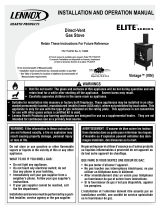
KIT CONTENTS
1 ea. Blower Assembly (item #1)
2 ea. Washers, #10 (item #2)
2 ea. Nuts, 10-24 Nylock (item #3)
1 ea. Instruction Sheet
NOTE: DIAGRAMS & ILLUSTRATIONS ARE NOT TO SCALE
TURN OFF THE STOVE AND ALLOW IT TO COMPLETELY COOL BEFORE
PROCEEDING.
INSTALLATION INSTRUCTIONS
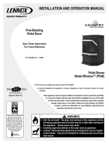
Step 1. Using an allen wrench, remove socket head screw A that secures the
heat shield to the bottom of the stove. See Figure 2.
Step 2. Using pliers, twist and break off section B of the heat shield (shown
as hatched section B in Figure 2). Discard this piece after removing.
Figure 1 - Kit Contents
Figure 2
TOOLS NEEDED
5/32” Allen Wrench Or T-Handle Wrench
3/8” End Wrench
Pliers
GENERAL INFORMATION
This optional 150-CFM blower for the Vintage gas stove provides variable
speed control, thermal activation and forced air circulation of the warm air
into the room.
If you encounter any problems, need clarification of these instructions or are
not qualified to properly install this kit, contact you local distributor or dealer.
Read this instruction sheet in its entirety before beginning the installation.
ALL WARNINGS AND PRECAUTIONS IN THE INSTALLATION AND OPERA-
TION MANUAL PROVIDED WITH THE APPLIANCE APPLY TO THESE
INSTRUCTIONS.
A
B
Heat Shield
Stove Bottom
Stove Back
A
B
B
1
2
3
2. Remove Section B
and Discard
1. Remove
Screw A

2
NOTE: DIAGRAMS & ILLUSTRATIONS ARE NOT TO SCALE.
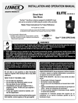
Step 3. Remove the blower from the box and unwrap it. The blower has a
rubber grommeted hole at each end (see Figure 3). Position the
blower under the stove so the grommets are up and the blower
control knob is at the left side (the left side is determined by standing
in front of the stove looking at it). The grommeted holes slide over
the two threaded studs located at the bottom rear of stove. See
Figures 3 and 4.
Step 4. After placing the blower’s grommeted holes over the studs, slide
a washer over each stud and then secure the blower with the nuts
provided. See Figure 4.
Figure 4 - Blower Installation
Figure 3 - Mounting Studs
Figure 5 - Completed Installation
Blower
Mounting Studs
Stove Bottom
Stove Bottom
Stove Back
Stove Back
Studs
Washers
Nuts
Mounting hole grommets, shown here, fit
over existing studs on stove bottom
Blower Assembly
Blower Assembly
Installed
Stove Back
Stove Bottom

3
NOTE: DIAGRAMS & ILLUSTRATIONS ARE NOT TO SCALE.
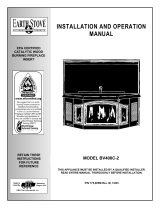
Figure 6 - Blower Control Knob
Vintage™ 27 Blower Wiring Diagram
Blower Operation
The blower will come on when the stove is up to temperature and shut
off when the stove cools. The blower control knob must be turned “ON”
for the blower to operate (see Figure 6).
Blower Control Knob - The highest blower speed is obtained by turning
the control knob clockwise until it clicks “ON.” Continue to rotate the knob
clockwise for a lower speed. To turn off, rotate the knob counterclockwise
until it clicks “OFF.”
WARNINGS
Once the new blower is properly installed, it must be
plugged directly into a properly grounded three-prong
receptacle, 120 VAC, 60 Hz, single phase power supply.
Do not cut or remove the grounding prong from this plug.
Do not route power cord under or in front of appliance.
Ground supply (green) lead must be connected to the
wire attached to the green ground screw located on the
unit or blower assembly. Failure to do so will result
in a potential safety hazard. The appliance must be
electrically grounded in accordance with local codes
or, in the absence of local codes, the National Electri-
cal Code, ANSI/NFPA 70-latest edition. (In Canada, the
current CSA C22-1 Canadian Electrical Code).
Blower Snap Switch - N/O
BLOWER
Blower Speed Control
Speed Control
Wire (Red)
Snap Switch
Connection Wire
(Black)
Speed Control
Connection Wire (Black)
N/O - Normally Open (Contacts
Close When Stove Is Hot)
Main Power Cord
Wire (Black)
Main Power Cord
Wire (White)
Ground Wire
(Green)
Main Power Cord
Wire (Black)
Speed Control Wire (Red)
Control Knob
Figure 7 - Wiring Diagram
CAUTIONS
• Disconnect the plug from receptacle prior to servicing the
blower.
• Label all wires prior to disconnection when servicing controls.
Wiring errors can cause improper and dangerous operation.
• Verify proper operation after servicing.
Blower
Control Knob
Left Side of Stove

4
Printed in U.S.A. © 2010 Lennox Hearth Products
P/N 775202M REV. A 01/2011
Lennox Hearth Products reserves the right to make changes at any time, without notice, in
design, materials, specifications, prices and also to discontinue colors, styles and products.
Consult your local distributor for fireplace code information.
1508 Elm Hill Pike, Suite 108 • Nashville, TN 37210
/