
# 48392M005 Page 1
Save these instructions for future reference
INSTALLATION AND
MAINTENANCE INSTRUCTIONS
(2,4)SA13 Series
Electric Cooling Package Unit
Improper installation, adjustment, alteration, service, or maintenance can cause injury or
property damage. Refer to this manual. For assistance or additional information, consult a
qualified installer or service agency.
WARNING
Sharp metal edges can cause injury. When
installing the unit, use care to avoid sharp
edges.
WARNING
Installation and servicing of air conditioning
equipment can be hazardous due to internal
refrigerant pressure and live electrical compo-
nents. Only trained and qualified service
personnel should install or service this equip-
ment. Installation and service performed by
unqualified persons can result in property
damage, personal injury, or death.
WARNING
The installation of this appliance must conform to the requirements of the National Fire Protection Association;
the National Electrical Code, ANSI/NFPA No. 70 (latest edition) in the United States; the Canadian Electrical
Code Part 1, CSA 22.1 (latest edition) in Canada; and any state or provincial laws or local ordinances. Local
authorities having jurisdiction should be consulted before installation is made. Such applicable regulations or
requirements take precedence over the general instructions in this manual.
CAUTION
TABLE OF CONTENTS
INSTALLATION ...................................... 2
OPERATION .......................................... 7
MAINTENANCE..................................... 8
WIRING DIAGRAM ................................ 9
WARRANTY ........................................ 10
Manufactured By
A.A.C.
A Lennox International Inc. Company
421 Monroe Street
Bellevue, OH 44811
If this unit is to be installed in a mobile or manu-
factured home application, the ductwork must
be sized to achieve static pressures within the
manufacturer’s guidelines. All other installation
guidelines must also be followed. Failure to do
so may result in equipment damage, personal
injury, and improper performance of the unit.
WARNING
*48392M005*

Page 2 # 48392M005
INSTALLATION
These instructions explain the recommended method of
installation of the SA electric cooling unit and associated
electrical wiring.
This unit is designed and approved for use as a self-
contained air-to-air air conditioning system.
The units are factory equipped with a transformer and
blower control for applications without auxiliary heat.
Electric heat accessory kits (PHK) can be ordered for field
installation of additional heat where required.
These instructions, and any instructions packaged with
mating components and/or accessories, should be care-
fully read prior to beginning installation. Note particularly
any CAUTIONS or WARNINGS in these instructions and
all labels on the units.
These instructions are intended as a general guide only, for
use by qualified personnel and do not supersede any national
or local codes in any way. Compliance with all local, state,
provincial, or national codes pertaining to this type of
equipment should be determined prior to installation.
IMPORTANT: This product has been designed and manufac-
tured to meet ENERGY STAR criteria for energy efficiency.
However, proper refrigerant charge and proper air flow are
critical to achieve rated capacity and efficiency. Installation
of this product should follow the manufacturer’s refrigerant
charging and air flow instructions. Failure to confirm
proper charge and airflow may reduce energy effi-
ciency and shorten equipment life.
Inspection of Shipment
Upon receipt of equipment, carefully inspect it for possible
shipping damage. If damage is found, it should be noted on
the carrier’s freight bill. Take special care to examine the
unit inside the carton if the carton is damaged. File a claim
with the transportation company.
If any damages are discovered and reported to the carrier
DO NOT INSTALL THE UNIT, as claim may be denied.
Check the unit rating plate to confirm specifications
are as ordered.
Limitations
The unit should be installed in accordance with all national
and local safety codes.
Limitations of the unit and appropriate accessories must
also be observed.
The unit must not be installed with any ductwork in the
outdoor air stream. The outdoor fan is not designed to
operate against any additional static pressure.
Location
The unit is designed to be located outdoors with sufficient
clearance for free entrance to the air inlet and discharge air
openings. The location must also allow for adequate
service access.
The unit must be installed on a solid foundation that will not
settle or shift. Adequate structural support must be pro-
vided. Maintain minimum clearances as shown in Figure 1
and Table 1 and install the unit in level position. Isolate the
base from the building structure to avoid possible transmis-
sion of sound or vibration into the conditioned space.
Avoid placing the unit near quiet areas such as
sleeping quarters or study rooms. Normal operating
sound levels may be objectionable if the unit is placed
near certain rooms.
Do not permit overhanging structures or shrubs to
obstruct condenser air discharge inlet or outlet.
For improved start-up performance, the indoor coil
should be washed with suitable detergent to remove
any residue from manufacturing processes.
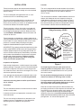
Exercise care when moving the unit. Do not remove any
packaging until the unit is near the place of installation. An
accessory lift kit can be purchased to aid in rigging (see
Figure 1). Spreaders whose length exceed the largest
dimension across the unit must be used across the top
of the unit. Recommended spreader length: 3 ton and smaller
package units – 44", 3.5 ton and larger units – 54".
Using Accessory Lift Kit
Figure 1
To avoid possible
damage to unit
panels from lifting
clevis, place
packing material
between clevis
and panels before
lifting unit.
Spreaders
(Field Supplied)
Lifting Bracket
Accessory
Sheet Metal
Screw

# 48392M005 Page 3
Before lifting a unit, make sure that the weight
is distributed equally on the cables so that it
will lift evenly.
CAUTION
Roof Curb Assembly
Figure 2
Units may also be moved or lifted with a forklift while still
in the factory-supplied packaging. The lengths of the
forks of the forklift must be a minimum of 42".
Ductwork
Ductwork should be designed and sized according to the
methods in Manual Q of the Air Conditioning Contractors of
America (ACCA).
A closed return duct system shall be used. This shall not
preclude use of economizers or outdoor fresh air intake. It
is recommended that supply and return duct connections
at the unit be made with flexible joints.
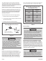
Unit
Drain Connection
Positive Liquid Seal Required
3.00" Min.
1.00" Min.
12.00"
Max.
Typical Condensate Drain Connection
Figure 3
Roof Curb Installation
If a roof curb is used, follow the manufacturer’s Installation
Instructions and be sure that all required clearances are
observed (see following Clearances section).
Clearances
All units require certain clearances for proper operation and
service. Refer to Table 1 for the minimum clearances to
combustibles as well as minimum clearances necessary
for servicing and proper unit operation.
In the U.S., units may be installed on combustible floors
made from wood or class A, B, or C roof covering material.
In Canada, units may be installed on combustible floors.
Service Access
Access to all serviceable components is provided by four
removable panels: filter compartment, blower compart-
ment, heater compartment, and top panel.
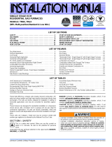
Condensate Drain
The SA package unit is equipped with a 3/4" FPT coupling
for condensate line connection. Plumbing must conform to
local codes. Use a sealing compound on male pipe threads.
The condensate drain line must be properly trapped
and routed to a suitable drain. See Figure 3 for proper
drain arrangement. The drain line must pitch to an open
drain or pump to prevent clogging of the line. Seal around
the drain connection with suitable material to prevent air
leakage into the return air system.
Table 1
oT
elbitsubmoC
lairetaM
roF
ecivreS
roF
reporP
noitarepO
tnorF"0"84"3
raeR "0 "42 "3
resnednoC
dnE
"0"42"3
rewolB
dnE
"0 "03 "0
poT"0"63"63
Minimum Clearance Requirements

Page 4 # 48392M005
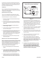
Figure 4
Removing Bottom Duct Covers
Base
1. Remove screw and lift.
2. Slide cover to free back pin.
1
2
When fastening ductwork to side duct flanges
on unit, insert screws through duct flanges
only; do not insert screws through casing. If
using bottom duct work, do not use screws to
secure ductwork to bottom duct opening
under drain pan side. Using screws to secure
bottom duct may damage drain pan.
CAUTION
The supply and return air duct systems should be de-
signed for the CFM and static requirements of the job.
They should not be sized by matching the dimensions
of the duct connections on the unit.
Outdoor ductwork must be insulated and waterproofed.
Equipment is shipped for side ductwork connection. The
unit can be converted to bottom ductwork connection by
removing the duct covers located over the bottom duct
openings and placing these covers over the side duct
openings (see Figure 4).
To remove the bottom duct cover over supply opening:
1. Remove screw on cover nearest side opening.
2. Lift end of cover slightly and push to slide back screw/
pin free from duct flange.
3. Slide duct cover out the side duct opening.
Table 2
Minimum Required Surface Area
for Disposable Filters
gnilooClanimoN
aerAretliF
).tf.qs(
000,4276.2
000,03 33.3
000,6300.4
000,24 76.4
000,8433.5
000,06 76.6
When connecting electrical power and control
wiring to the unit, waterproof type connectors
must be used so that water or moisture cannot
be drawn into the unit during normal operation.
CAUTION
Electrical Wiring
All wiring should be done in accordance with the
National Electrical Code, ANSI/NFPA No. 70 (latest
edition); Canadian Electrical Code Part 1, CSA C22.1
(latest edition); or local codes where they prevail. Use
wiring with a temperature limitation of 75°C minimum. Run
the 208 or 230 volt, 60 hertz electric power supply through
a fused disconnect switch to the connection box of the unit
and connect as shown in the wiring diagram located on the
inside of the control access panel.
Line voltage is present at all components when
unit is not in operation on units with single pole
contactors. Disconnect all remote electric
power supplies before opening access panel.
Unit may have multiple power supplies. Failure
to disconnect all power supplies could result in
personal injury or death.
WARNING
Filters
Air filters are to be used with this heating/cooling unit.
Filters are not factory supplied in the unit. However, a filter
frame accessory is available from the manufacturer that
allows filters to be installed within the unit. If the filter
frame accessory is not used, a filter must be installed in
the duct work by the installer. Filters must always be
installed ahead of the evaporator coil and must be kept
clean or replaced. Dirty filters will reduce the airflow of the
unit. Filters should be sized in accordance with Table 2.

# 48392M005 Page 5
Figure 5
Electrical Access
Heater Power Entry
Thermostat
Entry
Line Voltage
Entry
Unit must be grounded in accordance with
national and local codes. Failure to ground unit
properly can result in personal injury or death.
WARNING
Power supply to the unit must be N.E.C. Class 1, and must
comply with all applicable codes. A fused disconnect switch
should be field provided for the unit. The switch must be
separate from all other circuits.
If any of the wire supplied with the unit must be replaced,
replacement wire must be of the type shown on the wiring
diagram. Electrical wiring must be sized to carry minimum
circuit ampacity marked on the unit. Use copper conduc-
tors only. Each unit must be wired with a separate branch
circuit and be properly fused.
Figure 6
Typical Wiring Connections
RR
CC
CC
RR
L2 L1
YY Y1
Y
L1L2L3
POWER WIRING
208/230-1-60
(90°C MIN. WIRE)
POWER WIRING
24V CONTROL WIRING
(NEC CLASS 2)
TYPICAL WIRING CONNECTION
1 PHASE
GROUND
SCREW
THERMOSTAT
OUTDOOR UNIT
THERMOSTAT
OUTDOOR UNIT
GROUND
SCREW
POWER WIRING
200/230-3-60, 460/575-3-60
(90°C MIN. WIRE)
24V CONTROL WIRING
(NEC CLASS 2)
POWER WIRING
TYPICAL WIRING CONNECTION
3 PHASE
* W1, W2 CAN BE USED TO STAGE ELECTRIC
HEAT ACCESSORY ON MODELS.15 & 20 KW
* 5 & 10 KW HEATER ACCESSORY FUNCTION
W1 ONLY.OFF
* W1, W2 CAN BE USED TO STAGE ELECTRIC
HEAT ACCESSORY ON 15 & 20 KW MODELS.
* 10 KW HEATER ACCESSORY FUNCTION OFF
W1 ONLY.
ECONOMIZER
NOT
INSTALLED
ECONOMIZER
W1
W
W
W1
G G
GG
W2
Y2
W2
BLUE
WHITE
YELLOW
GREEN
BLACK
Do not connect connections except when
required by the indoor thermostat. Refer to the
thermostat installation instructions.
C
CAUTION
Do not connect connections except when
required by the indoor thermostat. Refer to the
thermostat installation instructions.
C
CAUTION
Thermostat
The room thermostat should be located on an inside wall
where it will not be subject to drafts, sun exposure, or heat
from electrical fixtures or appliances. Follow the

Page 6 # 48392M005
manufacturer’s instructions enclosed with thermostat for
general installation procedure. Color-coded insulated wires
(#18 AWG) should be used to connect thermostat to unit.
Four wires are required for cooling.
Compressor
Units are shipped with compressor mountings factory-
adjusted and ready for operation. Caution: Do not loosen
compressor mounting bolts.
Heater Kit Accessory (if used)
The unit is fully equipped for cooling operation without
auxiliary heat. A heater kit accessory may also be used.
To install the heater kit accessory (see Figure 7):
1. Disconnect the power and remove the heater compart-
ment access panel.
2. Disconnect the plug separating the high voltage wire
harness. Remove the high voltage wire harness plug
and discard.
3. Remove the heater blockoff by removing the four
screws holding it in place.
4. Insert the heater into the control panel and fasten in
the same mounting holes.
5. Plug the heater wiring harness into the wire harness on
the control assembly. Field wiring of the auxiliary
heater is separate from the unit power supply. Wire the
power supply wiring for the heater to the appropriate
connections on the heater kit.
6. Replace the heater compartment access panel and
reconnect the power.
Removal of Unit from Common Venting System
When an existing furnace is removed from a common venting
system serving other appliances, the venting system is likely
to be too large to properly vent the remaining attached
appliances. The following test should be conducted with each
appliance while the other appliances connected to the
common venting system are not in operation.
1. Seal any unused openings in the common venting
system.
2. Visually inspect the venting system for proper size
and horizontal pitch and determine there is no block-
age or restriction, leakage, corrosion, or other deficien-
cies which could cause an unsafe condition.
3. Insofar as is practical, close all building doors and
windows between the space in which the appliances
remaining connected to the common venting system
are located and other spaces in the building. Turn on
clothes dryers and any appliance not connected to the
common venting system. Turn on exhaust fans, such
as range hoods and bathroom exhausts, so they will
operate at maximum speed. Do not operate a summer
exhaust fan. Close fireplace dampers.
4. Following the lighting instructions, place the unit being
inspected in operation. Adjust the thermostat so the
appliance will operate continuously.
5. Test for spillage at the draft control relief opening after
5 minutes of main burner operation. Use the flame of a
match or candle.
6. Follow the preceding steps for each appliance con-
nected to the common venting system.
7. After it has been determined that each appliance
remaining connected to the common venting system
properly vents when tested as outlined above, return
doors, windows, exhaust fans, fireplace dampers, and
any other fuel burning appliance to their previous
condition of use.
8. If improper venting is observed during any of the
above tests, the common venting system must be
corrected. See National Fuel Gas Code, ANSI
Z223.1 (latest edition) or CAN/CGA B149.1 & .2
Canadian Installation Codes to correct improper
operation of common venting system.
Heater Kit Accessory Installation
Figure 7
Heater Kit
Heater
Blockoff
Heater
Compartment
Access
Panel

# 48392M005 Page 7
OPERATION
Sequence of Operation
Cooling
Upon cooling demand, the thermostat closes circuit R and Y.
Closing R and Y closes the unit contactor, starting the
compressor and outdoor fan. The thermostat automatically
closes R to G circuit which also brings on the indoor blower at
the same time. Upon satisfying cooling demand, the thermo-
stat will open the above circuits and open the main contactor,
stopping the compressor and outdoor fan. If the unit is
equipped with a delay timer, the blower will continue to
operate for 90 seconds which improves system efficiency.
Circulating Air Blower
The circulating air blower is controlled by a timing circuit in the
blower control. Timings are not adjustable.
There is no blower “on” delay after a call for heating or
cooling. Blower “off” delay is 90 seconds after the thermo-
stat is satisfied.
Cooling System Performance
For maximum performance of the cooling system, operat-
ing temperatures and pressure should be checked. Super-
heat should be determined at Standard ARI test conditions
of 82°F outdoor and 80°F indoor dry bulb/67°F wet bulb. If
superheat measured deviates from values found in Table 3,
refrigerant charge should be adjusted accordingly for
maximum performance.
Suction Superheat
Table 3
eziS
taehrepuSnoitcuS
snoitidnoCIRA@
BWDI°76/BDDI°08-DO°28
22R A014
42°22°51
03 °02 °51
63°02°21
24 °02 °21
06,84°02°01

Page 8 # 48392M005
Owner Record
Model # _________________________________
Serial # _________________________________
Installation Date ___________________________
Installed by:
Dealer __________________________________
Address _________________________________
Telephone # ______________________________
License # ________________________________
Periodic inspection and maintenance normally consists of
changing or cleaning the filters and cleaning the outdoor coil.
On occasion, other components may also require cleaning.
Filters
Filters should be checked at least every 6 weeks. Dispos-
able filters should be replaced when dirty, and cleanable
filters should be cleaned regularly. It is important to keep
the air filters clean, as dirty filters can restrict airflow and
the blower motor depends upon sufficient air flowing
across and through it to keep from overheating.
Motors
Indoor and outdoor fan and vent motors are permanently
lubricated and require no maintenance.
Outdoor Coil
Dirt and debris should not be allowed to accumulate on the
outdoor coil surface or other parts in the air circuit. Clean-
ing should be as often as necessary to keep coil clean.
Use a brush, vacuum cleaner attachment, or other suitable
means. If water is used to clean the coil, be sure the power
to unit is shut off prior to cleaning. Care should be used
when cleaning the coil so that the coil fins are not
damaged.
Do not permit the hot condenser air discharge to be
obstructed by overhanging structures or shrubs.
MAINTENANCE
Failure to follow the safety warnings exactly
could result in dangerous operation, serious
injury, death, or property damage.
Improper servicing could result in dangerous
operation, serious injury, death, or property
damage.
• Before servicing, disconnect all electrical
power to unit.
• When servicing controls, label all wires prior
to disconnecting. Reconnect wires correctly.
• Verify proper operation after servicing.
WARNING
ELECTRICAL SHOCK, FIRE,
OR EXPLOSION HAZARD

# 48392M005 Page 9
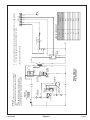
Figure 9
Wiring Diagram
P/N 48396-001
208/230V-1-60
G
W1
C
R
BLK
RED
YEL
RED
CONTACTOR
THERMOSTAT
L1
T1
T2
L2
C
H
F
CONDENSER
FAN MOTOR
COMPRESSOR
CONTACTOR
COMPRESSOR
CONTACTOR
DUAL
CAPACITOR
COMPRESSOR
TRANSFORMER
C
S
R
WHT
L2
L1
BLK
BRN
PUR
RED
RED
BLK
208V
240V
24V
INDOOR
BLOWER
MOTOR
S1
K1
T1
B3
B4
K1-2
C12
B1
K1-1
BLU
YEL
C4
CAPACITOR
H
M
L
C
SEE CHART
FOR WIRING
L
MOTOR
SPEED TAPS
NO
NC
C
BLOWER
CONTROL
A15
BLK
C
G
XFMR-R
R
XFMR-C
FUSE
Y
A15
BLOWER
GRN
RED
BLU
BLU
YEL
BLU
W1 & W2 CAN BE USED TO STAGE ELECTRIC HEAT ACCESSORY ON 15 & 20KW MODELS.
5, 7.5 & 10KW HEATER ACCESSORIES FUNCTION OFF W1 ONLY.
BLK
BLK
WHT
P-1
P-2
P-4
P-6
P-5
BLU
YEL
YEL
HIGH PRESSURE
SWITCH
(IF USED)
S4
GRN
RED
YEL
P-3
BLU
CHM
Unit
Factory Shipped
Settings
Cooling Input (BLK)
24 LOW
30 MED
36 HIGH
42 LOW
48 MED
60 HIGH
BLOWER SPEED CHART
CONTROL
NOTE:
IF ANY OF THE ORIGINAL WIRE IS REPLACED,
THE SAME SIZE AND TYPE WIRE MUST BE USED.
USE COPPER CONDUCTOR ONLY, MIN 75°C WIRE.
LINE VOLTAGE FIELD INSTALLED.
WARNING-
ELECTRIC SHOCK HAZARD. UNIT MUST BE GROUNDED
IN ACCORDANCE WITH NATIONAL AND LOCAL CODES.

Page 10 # 48392M005
Limited Warranty
August 1, 1997
This warranty gives you specific legal rights and you may have other rights
which vary from state/province to state/province.
Subject to the limitations stated in this warranty, we warrant to the first buyer for use the residential heating, cooling, or heat pump unit,
when installed, operated, and maintained as required by this warranty, to be free of defects in workmanship or material for a period of
5 years in residential installations (1 year in non-residential installations) from the time of installation. We will replace any defective
component without cost or expense to you except for the costs of delivery and labor for removal and replacement of the defective
component.
These (2/4)SA13 package cooling units carry a 5-year limited warranty on the compressor. Limited warranties apply to
the original owner in private owner-occupied residences.
Warranty Begins
The warranty period begins when the installation is complete and the product is ready to operate. You must be able to verify this date
whenever a warranty claim is made. Original bill of sale, installer’s invoice, or other similar document will suffice. If the beginning date
cannot be verified, we will consider warranty coverage to begin 6 months after the date the product was shipped from our factory.
Limitations on Implied Warranties
Implied warranties of merchantability or, to the extent applicable, fitness for a particular purpose are limited to 5 years, the same duration
as the basic limited written warranty provided herein. Some states/provinces do not allow limitations on how long an implied warranty of
merchantability or fitness lasts, so the above limitations or exclusions may not apply to you.
Only Warranty
This written Limited Warranty is the only warranty made by the warrantor; this warranty is in lieu of and excludes all other warranties,
express or implied. The warrantor does not authorize any person to provide any other warranty or to assume for it any further
obligation in connection with the warranted product.
What is NOT Covered
1. Cabinets or cabinet pieces.
2. Normal maintenance items such as filters, fan belts, fuses, or other consumable items.
3. Damage caused by misuse, failure to maintain properly, accidents, or acts of God.
4. External wiring, piping, venting, or attachment of accessory products not integral to our product, including without limitation,
humidifier, air cleaner, vent damper, thermostat, or other mechanical devices not manufactured by the warrantor.
5. Products that have been operated in a corrosive atmosphere where a concentration of acids, halogenated hydrocarbons,
or other corrosive elements causes deterioration to metal surfaces or integral components. NOTE: Operation in a corrosive
atmosphere is considered abuse and voids this warranty.
6. Products that have NOT been installed in accordance with our published installation instructions, applicable local, state/
provincial, or national codes, ACCA published standards.
7. Products that have NOT been installed by competent, qualified installers.
8. Products that have been moved from their original place of installation.
Warranty on Replacement Components
Any replacement component furnished by us will assume the remaining (unused) portion of the Limited Warranty.
Consequential Damages
The warrantor shall not be responsible for any consequential damages caused by any defect in the product. Some state/provinces do
not allow the exclusion or limitations of incidental or consequential damages, so the above limitation or exclusion may not apply to you.
This product must be installed, used, and cared for in accordance with the instruction manual. You are responsible for required periodic
maintenance or service, such as changing or cleaning of air filters and lubrication or cleaning of components. Failure to properly install,
operate, or maintain your unit voids this warranty.
-
 1
1
-
 2
2
-
 3
3
-
 4
4
-
 5
5
-
 6
6
-
 7
7
-
 8
8
-
 9
9
-
 10
10


Ask a question and I''ll find the answer in the document
Finding information in a document is now easier with AI
Related papers
Other documents
-
 Allied Air 4SG13 series User manual
-
Allied 2PHP15 Series User manual
-
COMFORT-AIRE TPRG36001M-CY Operating instructions
-
Allied PRHP14 Installation guide
-
COMFORT-AIRE TARG60001P-CY Operating instructions
-
COMFORT-AIRE TGRG601261M Operating instructions
-
Johnson Controls PCE4B60 Installation guide
-
Carrier 50QQ User manual
-
 Johnson Controls Unitary Products TM8X Installation guide
-
Carrier 50GS024300 Installation guide

