APC Smart-UPS
Uninterruptible Power Supply
120 VAC User’s Manual
990-7016B, Revision 3
Initial Start-Up
To obtain warranty coverage, please fill out and return the
warranty registration card now.
Inspection
Inspect the UPS upon receipt. Notify the carrier and dealer if there
is damage. The packaging is recyclable; save it for reuse or
dispose of it properly.
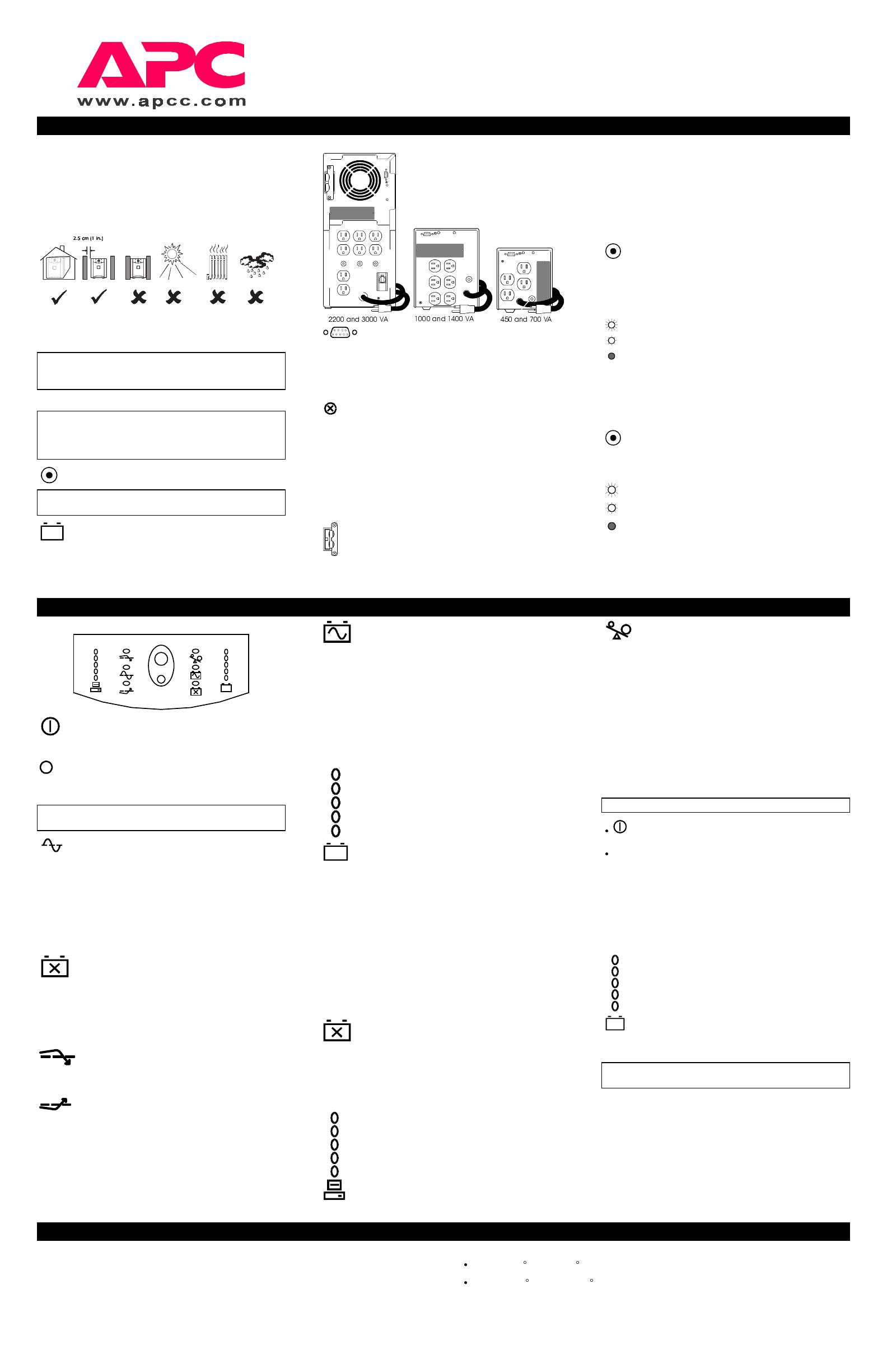
Placement
Install the UPS in a protected area that is free of excessive dust
and has adequate air flow. Do not operate the UPS where the
temperature and humidity is outside the specified limits.
Warning: Changes or modifications to this unit not expressly
approved by the party responsible for compliance could void
the warranty.
Installation
To install this UPS, please follow the installation instructions
in the Smart-UPS Quick Reference Guide.
This UPS is equipped with a SmartSlot for accessories. See
the APC Website (www.apcc.com) for available accessories.
Check the Site Wiring Fault Indicator
Caution: If the site wiring fault indicator lights, get a
qualified electrician to correct the building wiring.
Charge the battery
The UPS charges its battery whenever it is connected to utility
power. The battery will charge fully during the first 4 hours of
normal operation. Do not expect full runtime during this initial
charge period.
Rear Views
Connect Computer Interface Port (Optional)
Power management software and interface kits can be used with
this UPS. Use only kits supplied or approved by the manufacturer.
If used, connect the interface cable to the 9-pin computer interface
port on the back panel of the UPS. Secure the connector’s screws
to complete the connection.
Connect Ground Leads to TVSS Connector
(Optional)
The UPS features a TVSS connector for connecting the ground
lead on transient voltage surge-suppression (TVSS) devices such
as telephone and network line protectors. The TVSS connector
provides grounding through the UPS’s power cord ground
conductor. To make a connection to the TVSS connector, loosen
the screw and connect the surge suppression device’s ground lead.
Tighten the screw to secure the lead.
Battery Pack Connector (3000 VA only)
Use the battery pack connector to connect the optional
external battery pack.
Voltage Sensitivity
The UPS detects line voltage distortions such as spikes, notches,
dips, and swells, as well as distortions caused by operation with
inexpensive fuel-powered generators. By default, the UPS reacts
to distortions by transferring to on-battery operation to protect the
loads. Where power quality is poor, the UPS may frequently
transfer to on-battery operation. If the loads can operate normally
under such conditions, battery capacity and service life may be
conserved by reducing the sensitivity of the UPS.
To reduce UPS sensitivity, press the configuration button on
the rear panel. Use a pointed object such as a pen to press the
button. Press it once to set the UPS’s sensitivity to reduced. Press
it again to set the sensitivity to low. Press the button a third time
to reset normal sensitivity.
When the UPS is set to normal sensitivity, the
configuration LED is brightly lit. When it is set to
reduced sensitivity, the LED is dimly lit. When it is
set to low sensitivity, the LED is off.
Low Battery Warning Interval
By default, the low battery warning occurs when there are
approximately two minutes of on-battery run time remaining. This
may not be enough time to gracefully shut down some protected
computer systems.
To change the warning interval, press the rear panel
configuration button while pressing and holding the front-panel
on/test button.
Press the configuration button once to set the low
battery warning interval to approximately five
minutes. Press it again to set the interval to
approximately seven minutes. Press the button a
third time to reset the interval to two minutes.
Operating Instructions
Switch On — Switch Off
With the UPS plugged in, press and release the large
upper on/test button to supply power to the loads. The
loads are immediately powered while the UPS performs a
self-test.
Press and release the small, lower off button to turn off power
to the loads. It may be convenient to use the UPS as a master
on/off switch for the protected equipment.
Note: Whenever the UPS is plugged in and utility voltage is
present, the charger maintains battery charge.
The on-line LED illuminates when the UPS is supplying
utility power to the loads.
Self-test
The UPS performs a self-test automatically when turned on, and
every two weeks thereafter (by default). Automatic self-test eases
maintenance requirements by eliminating the need for periodic
manual self-tests.
During the self-test, the UPS briefly operates the loads on-battery.
If the UPS passes the self-test, it returns to on-line operation.
If the UPS fails the self-test it immediately returns to on-
line operation and lights the replace battery LED.
The loads are not affected by a failed test. Recharge the battery
overnight and perform the self-test again. If the replace battery
LED is still on, replace the battery using the Replacing the
Battery procedure.
SmartTrim
The SmartTrim LED comes on to indicate that the UPS is
compensating for a high voltage.
SmartBoost
The SmartBoost LED comes on to indicate that the UPS is
compensating for a low voltage.
On Battery
During on-battery operation, the on-battery LED illuminates and
the UPS sounds an audible alarm consisting of four beeps every
30 seconds. The alarm stops when the UPS returns to on-line
operation.
Low Battery
When the UPS is operating on-battery and the energy reserve of
the battery runs low, the UPS beeps continuously until the UPS
shuts down from battery exhaustion or returns to on-line
operation.
Battery Charge Bar Graph
The 5-LED display on the right of the front panel
shows the present charge of the UPS’s battery as a
percentage of the battery’s capacity. When all five
LEDs light, the battery is fully charged. The top
LED goes out whenever the battery is not 100%
charged. When the LEDs are flashing, the battery
can supply less than the “low battery warning
interval” time for the load.
Shutdown Mode
If there is no utility power present, a host system connected to the
computer interface port can command the UPS to shut down.
This is normally done to preserve battery capacity after a
controlled shutdown of the protected system. In shutdown mode
the UPS stops supplying power to the load, waiting for the return
of utility power.
The UPS scrolls the front panel indicators sequentially in
shutdown mode. If the UPS has shutdown due to a low battery,
the UPS lights the Battery Charge Bar Graph only. When line
power is restored, the UPS returns to on-line operation.
Replace Battery
If the battery fails a self-test, the UPS emits short beeps for one
minute and the replace battery LED illuminates. The UPS
repeats the alarm every five hours. Perform the self-test procedure
to confirm replace battery conditions. The alarm stops when the
battery passes the self-test.
Load Bar Graph
The 5-LED display on the left of the front panel
shows the power drawn from the UPS by the load.
The display indicates the percentage of the UPS’s
rated capacity. For example, if three LEDs are lit, the
load is drawing between 50% and 67% of the UPS’s
capacity. If all five LEDs light, thoroughly test your
complete system to make sure that the UPS will not
become overloaded.
Overload
When loads exceed the UPS’s capacity, the overload LED
illuminates, the UPS emits a sustained tone, and the input circuit
breaker may trip (the resettable center plunger of the circuit
breaker pops out). The alarm remains on until the overload is
removed. Disconnect nonessential load equipment from the UPS
to eliminate the overload. If there is AC power and the circuit
breaker does not trip during overload, the loads are still powered.
If the circuit breaker trips and the UPS attempts to go on-battery,
the output AC will shut down.
Cold Start
When the UPS is off and there is no utility power, it is possible to
cold start the UPS to power the loads from the UPS’s battery.
Note: Cold start is not a normal condition.
Press and hold the on/test button until the UPS begins
beeping.
Release the on/test button during the beeping to start the UPS.
Utility Voltage Bar Graph
This UPS has a diagnostic feature that displays the utility voltage.
With the UPS plugged into the normal utility power, press and
hold the on/test button to see the utility voltage bar graph display.
After approximately four seconds the 5-LED display on the right
of the front panel shows the utility input voltage. Refer to the
figure below for the voltage reading.
The display indicates that the voltage is between the
displayed value from the list and the next higher value.
For example, with three LEDs lit, the input voltage is
between 115 and 123 VAC.
If no LEDs come on and the UPS is plugged into a
working AC power outlet, the line voltage is extremely
low.
If all five LEDs come on, the line voltage is extremely high and
should be checked by an electrician.
Note: The UPS starts a self-test as part of this procedure. The
self-test does not affect the voltage display.
Storage
Storage Conditions
Store the UPS covered and upright in a cool, dry location, with its battery fully charged. Before storing,
charge the UPS for at least 4 hours. Disconnect any cables connected to the computer interface port to
avoid unnecessarily draining the battery.
Extended storage
At -15 to +30 C (+5 to +86 F), charge the UPS’s battery every 6 months.
At +30 to +45 C (+86 to +113 F), charge the UPS’s battery every 3 months.
normal
reduced
low
2 min.
5 min.
7 min.
100%
80%
60%
40%
20%
85%
67%
50%
33%
17%
132
123
115
107
98


