Multi-Band
Vertical Antenna
160 through 10 Meters
with the patented
SAF-T-TILT™ Base
DXE-MBVE-5A Series
US Patent Nos. 654,064 and 8,686,919
DXE-MBVE-5A-Series - INS-Revision 1a
© DX Engineering 2017
1200 Southeast Ave. - Tallmadge, OH 44278 USA MBVE-5 Shown with optional UNUN
Phone: (800) 777-0703 ∙ Tech Support and International: (330) 572-3200
Fax: (330) 572-3279 ∙ E-mail: [email protected]

- 1 -
Table of Contents
Introduction
2
Manual Updates
2
DXE-MBVE-5A Models Available
3
DXE-MBVE-5A Remote Tuner Upgrades Available
3
Tools Required
4
Warning
5
Suggested Parts
5
Additional Material Needed, Not Supplied
6
Basics for All New Installations
7
Site Selection
7
Radial System
7
Mounting Pipe
8
Assembly
8
Radial Plate to Mounting Pipe
9
Attaching Ground Radial Wires to the Radial Plate
10
Tilt Base to Mounting Pipe
10
SAF-T-TILT™ Antenna Base Section Assembly
12
Aluminum Tubing Information
14
Assembling the Vertical Sections
15
Mating the Vertical Sections to the Tilt Base
18
Raising The Vertical
20
Assembling the Optional UNUN Mounting Bracket
21
Installation of Optional UNUN Assembly
22
Feedline Connections
23
Tuning the Vertical
23
Coaxial Cable and 160 Meter Notes
24
Guying a Vertical Antenna System
25
DXE-MBVE-5A Parts List
26
Exploded View of the DXE-MBVE-5A
27
Appendix A - MFJ-927 Optional Remote Tuner
28
Appendix B - Extended Base Remote Tuner Options
30
Extended Base Tube Exploded View Drawing
31
Upgrade Hardware Exploded View Drawing
32
Appendix C - MFJ-993/994BRT Remote Tuner Option
34
Appendix D - MFJ-998RT Remote Tuner Option
37
Appendix E - Bias Tee Information
41
Parts Listings for DXE-MBVE-THW and TBHW
42
Parts Listings for DXE-MBVE-5A-UGHW
43
Optional Accessory Items
43
Technical Support and Warranty
47

- 2 -
Introduction
The DX Engineering DXE-MBVE-5A series of antennas are designed from the ground up to offer
ease of use, reliability and performance. A fast taper multi-band vertical antenna system with the
patented SAF-T-TILT™ base (US Patent Nos. 654,064 and 8,686,919). The massive 3/8” thick
rugged aluminum base allows easy, safe tilt action without unsafe removal of mounting hardware.
The vertical antenna operates from 160 meters through 10 meters using a good quality outboard
customer supplied tuner. There are also options available for remote tuners allowing operation at
200, 300, 600 or 1500 Watt power levels. There are no traps, coils or linear loading elements.
Designed with 6063 corrosion-resistant aluminum tubing and stainless steel hardware, this antenna
is very durable and attractive.
NOTE: The basic DXE-MBVE-5A requires an optional DX Engineering UN-43 UNUN and
optional UNUN Bracket DXE-UN-BRKT with recommended 150 feet of RG-213 coaxial cable
and a customer supplied in-shack wide range tuner or one of the optional remote tuners with remote
tuner mounting methods as described in this manual.
If you already own a DXE-MBVE-5 or 5A, there are optional upgrades available for use with
the remote tuner options for 200, 300, 600 or 1500 watt operation.
Basic DXE-MBVE-5A Antenna Features
Full band coverage from 160 through 10 meters - Outboard customer supplied wide-range
tuner is required
New massive SAF-T-TILT™ Base (US Patent Nos. 654,064 and 8,686,919) allows safe
raising and lowering of the antenna without hazardous removal of fastening hardware
High strength Delrin® thermoplastic insulator that won’t crack, splinter, peel or fail
Rugged structural grade type 6063-T832 drawn aluminum vertical radiator - the best alloy
for high strength, long lasting antenna applications
Fast taper from rugged base to sleek top for the lowest wind resistance
No coils or traps – Maximum radiation efficiency
Power handling up to 5 kW - built to last
All stainless steel hardware - very durable and attractive
Free standing to 92 mph wind speeds
Manual Updates
Every effort is made to supply the latest manual revision with each product. Occasionally a manual
will be updated between the time your DX Engineering product is shipped and when you receive it.
Please check the DX Engineering web site (www.dxengineering.com) for the latest revision manual.

- 3 -
DXE-MBVE-5A Models Available
DX Engineering
MBVE-5A
Model Numbers
SAF-T-TILT™ Base
DXE-MBVE-5A with
Short Base Tube
DXE-MBVE-5AE with
Long Base Tube
DXE-RADP-3 Radial Plate
DXE-UN-43 UNUN
and DXE-UN-BRKT
Mounting Bracket and
DXE-UNFK-5 UNUN to
MBVE-5 Feedpoint
Connection Kit
MFJ-927 Remote Tuner
200 Watt
MFJ-993/4BRT Brackets
MFJ-993BRT Tuner
300 Watt
MFJ-994BRT Tuner
600 Watt
MFJ-998RT Brackets
MFJ-998RT Tuner
1500 Watt
DXE-MBVE-5A
X
X
Req’d
DXE-MBVE-5A-4P
X
X
X
Req’d
DXE-MBVE-5A-4UP
X
X
X
DXE-MBVE-5A-4UPR
X
X
X
X
DXE-MBVE-5A-3ATP
X
X
optional
not applicable
X
DXE-MBVE-5AE-BRT
X
X
optional
not applicable
X
DXE-MBVE-5AEBRT3
X
X
X
not applicable
X
X
DXE-MBVE-5AEBRT4
X
X
X
not applicable
X
X
DXE-MBVE-5AE-RT
X
X
optional
not applicable
X
DXE-MBVE-5AERT8
X
X
X
not applicable
X
X
X = Included Reqd = Required (see text) optional = Purchase is optional (see text explaining the importance of a radial system)
DXE-MBVE-5A60MCK: Also available is a conversion kit to change the MBVE-5A Multi-
Band antenna into a 60 meter Mono-Band Antenna
DXE-MBVE-5 or 5A Remote Tuner Upgrade Models Available
If you are upgrading from an existing DXE-MBVE-5 or 5A system with the original short
base tube to a MBVE-5A with a MFJ-993BRT, MFJ-994BRT or MFJ-998RT remote tuner,
the following upgrade kit options are available.
Upgrade kits include new longer base tube, brackets, remote tuners as selected below.
DX Engineering
Upgrade Model
Numbers
DXE-MBVE-5AEBASE -
Long Base
DXE-RADP-3 Radial Plate
DXE-MBVE-THW
Hardware Kit
DXE-MBVE-TBHW
Hardware Kit
DXE-MBVE-5A-UGHW
Hardware Kit
MFJ-993/4BRT - Brackets
MFJ-993BRT - Tuner
300 Watt
MFJ-994BRT - Tuner
600 Watt
MFJ-998RT - Brackets
MFJ-998RT - Tuner
1500 Watt
DXE-MBVE-5UG-BRT
X
optional
X
X
X
DXE-MBVE-5UGBRT3
X
optional
X
X
X
X
DXE-MBVE-5UGBRT4
X
optional
X
X
X
X
DXE-MBVE-5UG-RT
X
optional
X
X
X
DXE-MBVE-5UGRT8
X
optional
X
X
X
X
X = Included optional = Purchase is optional (see text explaining the importance of a radial system)

- 4 -
PLEASE - Read the entire manual to be familiar with the various options
available. Some of the assembly steps are common for all models.
This manual describes in detail the DXE-MBVE-5A-4UPR antenna package
which includes the basic antenna with the DXE-RADP-3 Radial Plate, DXE-
43 UNUN and DXE-UN-BRKT.
Other sections in this manual describe the models using the remote tuner
options.
Refer to the DXE-MBVE-5A60MCK if you are converting the MBVE-5A to a
Mono-Band 60 Meter Antenna
Upgrade kits for existing MBVE-5/5A systems use the kit parts for MFJ-
993/994BRT or MFJ-998RT remote tuner option installations.
The vertical elements for all models are the same.
The SAF-T-TILT™ Base is the same for all models with one exception. The
thick wall base tube is longer for the tube mounted remote tuner options.
This manual describes in detail the DXE-MBVE-5A-4UPR antenna package which includes
the basic antenna with the DXE-RADP-3 Radial Plate, DXE-43 UNUN and DXE-UN-BRKT.
Tools Required
Two 7/16” wrenches, (one of them should be open-end)
5/16”, 3/8”, 9/16”, and 3/4” wrenches or
5/16”, 3/8”, 9/16”, and 3/4” sockets and drive
Medium size flat blade screwdriver or 5/16” nut driver for the element clamps
Medium size flat blade screwdriver or 1/4” nut driver for the smaller element clamps
Tape measure
Black Felt-tip marker or pencil

- 5 -
WARNING!
INSTALLATION OF ANY ANTENNA NEAR POWER LINES IS DANGEROUS
Warning: Do not locate the antenna near overhead power lines or other electric light or power
circuits, or where it can come into contact with such circuits. When installing the antenna, take
extreme care not to come into contact with such circuits, because they may cause serious injury or
death.
Overhead Power Line Safety
Before you begin working, check carefully for overhead power lines in the area you will be
working. Don't assume that wires are telephone or cable lines: check with your electric utility for
advice. Although overhead power lines may appear to be insulated, often these coverings are
intended only to protect metal wires from weather conditions and may not protect you from electric
shock. Keep your distance! Remember the 10-foot rule: When carrying and using ladders and other
long tools, keep them at least 10 feet away from all overhead lines - including any lines from the
power pole to your home.
Suggested Parts
DXE-RADP-3 - Radial Plate, Stainless Steel with 20 Sets of SS Radial Attachment Hardware
The patented DX Engineering Radial Plate is meant for those of you that have or are
building a quarter wave vertical antenna and who want an easy, neat and effective
way to connect those essential radial wires and the coax to your vertical antenna for
the lowest takeoff angle and strongest signals. DX Engineering Radial Plate is laser
cut from tough stainless steel so that it has smooth edges, won’t corrode and will
always look good. You will be proud of how good your installation looks. This plate
will work perfectly with most commercially available vertical antennas.
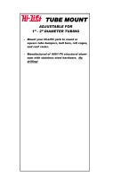
DXE-SSVC-2P - Stainless Steel V-Clamp for steel pipe, 2 inch V-bolt
This V-Clamp is made in one size that fits Steel tubing or pipe from 1" to 2'' OD as used in antenna
construction. The supplied V-bolt is long enough to attach tubing to thick plates and is
made with anti-corrosive properties. The special Stainless Steel saddle has serrated teeth
will clamp to the pipe securely by biting into the surface. For this reason, it is not
recommended for softer aluminum tubing or pipe. Ideal for fastening a radial plate and
antenna mounting to a steel pipe.
Used to clamp 1 to 2'' (OD) steel tubing or pipe
Designed for attachments that don't require resistance to torque
V-bolt and saddle made from high-strength 18-8* stainless steel
*The use of an anti-seize compound is HIGHLY recommended to
achieve proper torque and prevent galling.

- 6 -
DXE-RADW Radial Wire Kits and Components
There are optional DX Engineering Radial Wire Kits available. DXE-RADW-500K/BD contains a
500 foot spool of 14 gauge copper stranded wire with black relaxed PVC insulation, 20 Terminal
Lugs and 100 Steel or Biodegradable Lawn Staples. The DXE-RADW-1000K/BD Radial Wire Kit
contains a 1,000 foot spool of 14 gauge copper stranded wire with black relaxed PVC insulation, 40
Terminal Lugs and 200 Steel or Biodegradable Lawn Staples. RADW-20RT, -32RT or -65RT
contain 20 each radial wires with 1/4" terminal attached. These kits come in 20 Ft, 32 Ft, or 65 Ft
lengths.
DXE-GUY-200 Guying Kit for Vertical Antennas
Some vertical antenna manufacturers indicate their antennas do not need guying. During times of
high winds or ice loading, some of these vertical antennas may sustain damage or fail altogether.
With the small amount of effort needed to install a four point guying system, the risk hardly seems
worth taking. A four-point guying scheme provides the best mechanical advantage to reduce wind
stress, regardless of direction. A four point guying system is recommended for use with the DX
Engineering SAF-T-TILT™ Base, because just one of the guy ropes has to be loosened when you
tilt the vertical antenna down. The remaining guys help stabilize the vertical antenna in three
directions when being raised. For details on guying this antenna, refer to the Guying a Vertical
Antenna System page.
See these and other options available from DX Engineering for this antenna system in this manual
refer to the Optional Accessory Items page.
Additional Material Needed but not Supplied:
JTL-12555 Jet-Lube™ SS-30 Pure Copper Anti-Seize 12555 - To ensure good electrical
and RF connection for Aluminum Element Sections and also used on the threads of Stainless
Steel Hardware to prevent galling (seizing) and aid in proper tightening.
For a new installation: Antenna Mounting - Steel mounting pipe, up to 2.0″ OD, 0.25″
wall thickness, 4 feet long. The standard 1-1/2" galvanized water pipe (with its 1.9" OD) is
just fine for this application and can usually be found at your local home building supply
store.
For a new installation: Quick-Set or other type of Concrete - Mounting pipe installation
(type depends on your particular conditions and landscape).

- 7 -
Basics for All New Installations
Site Selection
Select a mounting location clear from power lines, structures and other antennas by a minimum of
55 feet. Consider overhead power lines, utility cables and wires. The vertical should be mounted
away from local noise sources or other metallic objects which can re-radiate noise and affect the
tuning, radiation pattern and SWR. Determine the direction you want the antenna to tilt down and
make sure there is adequate clearance (at least 55 feet). There should also be a clear diameter of 70
to 130 feet from the antenna for the guying and radial systems that will extend away from the
antenna.
Radial System
The use of a radial system is a key requirement for any high performance quarter wave vertical
antenna system. With a vertical antenna system, the radials are the second half of the antenna. The
radials contribute to the radiation efficiency of the entire vertical antenna system.
At a minimum, 20 radials, each 32 feet long, should be used with this antenna. Using 32 radials at
65 feet long is preferred and highly recommended. The extra radials help overcome unknown poor-
soil conditions, improve bandwidth, and ensure the best performance possible from the vertical
antenna. DXE-RADW Radial Wire, a 14 gauge stranded copper with black relaxed PVC insulation
wire is suggested for the best results.
The wire radials should placed as symmetrically as
possible straight from the feedpoint around the
vertical antenna and spaced evenly, regardless of
how many radials are used. Do not cross or bunch
any radial wires as this nullifies their effectiveness.
If you have limited space, put in as many straight
radials as you can. The radials must be connected
to the shield of your feedline. The DXE-RADP-3
Stainless Steel Radial Plate is the ideal optional
item which provides an excellent system for
attaching radial wires to your vertical antenna
system.
Radial wires can be laid on the roots of the grass
using DXE-STPL Radial Wire Anchor Pins to
hold them down. Using enough staples will ensure
the wires will not be snagged by mowers, people,
or animals. Grass will quickly overgrow the radials and it will be virtually impossible to see them.
An article describing this process is available on the DX Engineering website. Radials can also be
buried just under the surface by using a power edger to make a slit in the soil.

- 8 -
Mounting Pipe
Use a customer supplied thick-walled galvanized steel mounting pipe
at least 4 feet long. This will allow approximately 2 feet or more to
be below ground and 20 inches above ground. A thick-walled steel
pipe 1-3/4" OD to 2" OD maximum is recommended with a minimum
thickness of 1/8" (1/4" preferred) should be used. The standard 1-
1/2" galvanized water pipe (with its 1.9" OD) is just fine for this
application and can usually be found at your local home building
supply store. For permanent mounting, use a post-hole digger to
make the hole deep enough to accommodate at least 2 feet of pipe and
a couple inches of gravel at the bottom for drainage. Set the mounting
pipe on the gravel, use the pre-mix concrete to fill around the pipe,
adding water and mixing as you fill or mix the concrete first, then
pour in the hole (depends on the type of quick concrete you
purchase). Fill the hole until the concrete is level with the ground
around it. Use a level on the mounting pipe as you fill the hole to be
sure it is vertically straight. Allow to set overnight or per the concrete
manufacturer’s recommendations. Your location, landscape and
ground conditions may require different mounting solutions in order
to have the steel mounting pipe and the vertical antenna in a secure
position. A black vinyl cap (DXE-VC-2000, for 2” pipe) can be used to cap the top of the
mounting pipe to prevent water and debris from getting into the pipe.
NOTE: When installing the MFJ-927 Remote Tuner option at the base of the
antenna - the Mounting Pipe length above ground must be 24 inches to allow
room for the remote tuner and mounting shelf. Refer to the DXE-MBV-ATU-1
manual for details.
Note: Galvanized steel, rather than aluminum, is much more suitable for mounting in concrete.
Aluminum will quickly corrode due to incompatibility with the materials used to make
concrete.
Assembly
Carefully un-box the antenna and separate the various parts. All of the element sections are 36"
long. The 2-1/8" OD antenna element is slit on one end and drilled on the other end. All the other
sections are slit on one end except for the top 3/8” OD element.
Note: JTL-12555 Jet-Lube™ SS-30 Anti-Oxidant should be used between all antenna element
sections. Jet-Lube™ SS-30 is an electrical joint compound to affect a substantial
electrical connection between metal parts such as aluminum tubing or other antenna
pieces. It ensures high conductivity at all voltage levels by displacing moisture and
preventing corrosion or oxidation. Jet-Lube™ SS-30 should also be used on all element
clamps and stainless steel threaded hardware to provide good electrical contact,
prevent galling, allow easier disassembly and to ensure proper tightening.

- 9 -
Note: The following assembly instructions are based on the MBVE-5A-4UPR
which includes the DXE-RADP-3 Radial Plate and the DXE-UN-43
UNUN, DXE-UN-BRKT Bracket with hardware using a customer
supplied 2" OD Mounting Pipe.
Note: For reference purposes, an exploded drawing of the completed SAF-T-TILT™ base
is show in Figure 21.
Radial Plate to Mounting Pipe
Install the patented DXE-RADP-3 Radial Plate on the 2" OD customer supplied mounting pipe
using the DXE-SSVC-2P V-Bolt Saddle Clamp as shown in Figure 1. The standard 1-1/2"
galvanized water pipe (with its 1.9" OD) is just fine for this application and can usually be found at
your local home building supply store. Mount the Radial Plate so you have approximately 1" of
space between the bottom of the plate and the ground level. This will allow easy access to install
the radial wire hardware. The DXE-RADP-3 Radial Plate comes with 20 sets of stainless steel
hardware for mounting the radial wires. Additional hardware kits are available from DX
Engineering: DXE-RADP-1HWK contains 20 sets of Radial Plate Hardware. Check which
direction you want the antenna to tilt. Mount the radial plate as shown in relation to the SAF-T-
TILT™ Tilt Base. For reference, Figure 19 shows a completed installation.
Figure 1 - DXE-RADP-3 Radial Plate Installation on customer supplied mounting pipe

- 10 -
Attaching the optional Ground Radial Wires to the Radial Plate
Using the 20 sets of supplied 1/4" stainless steel hardware (Bolt, Star Washer, Flat Washer, Split
Washer, Nut) connect the optional ground radial wires to the DXE-RADP-3 Radial Plate as shown
in Figure 2. Additional hardware kits are available from DX Engineering: DXE-RADP-1HWK
contains 20 sets of Radial Plate Hardware.
There are optional DX Engineering Radial Wire Kits available. DXE-RADW-500K/BD contains a
500 foot spool of 14 gauge copper stranded wire with relaxed black PVC insulation, 20 Terminal
Lugs and 100 Steel or Biodegradable Lawn Staples. The DXE-RADW-1000K/BD Radial Wire Kit
contains a 1,000 foot spool of 14 gauge copper stranded wire with relaxed black PVC insulation, 40
Terminal Lugs and 200 Steel or Biodegradable Lawn Staples. RADW-20RT, -32RT or -65RT
contain 20 each radial wires with 1/4" terminal attached. These kits come in 20 Ft, 32 Ft, or 65Ft
lengths. See these and other options available listed at the end of this manual.
Depending on the number of radial wires used, space them out evenly around the Radial Plate like
the spokes on a wheel. The Radial Plate will accommodate up to 60 radial wires (60 laser drilled
holes), or up to 120 radials if doubled up.
Radial Wire Pattern
Figure 2 - Radial Wire Hardware Installation
Tilt Base to Mounting Pipe
Install the SAF-T-TILT™ Tilt Base to the 2" OD mounting pipe using the two 3/8” SSVC V-Bolt
Saddle Clamps allowing approximately 3-1/2" clearance between the bottom of the tilt base plate, to
the top of the DXE-RADP-3 Radial Plate as shown in Figure 3. (See note on page 8 if you are
using the MFJ-927 Remote Tuner - the mounting pipe above ground must be longer and the tilt base
moved upward). The standard 1-1/2" galvanized water pipe (with its 1.9" OD) is just fine for this
application and can usually be found at your local home building supply store.

- 11 -
Make sure the Tilt Base and DXE-RADP-3 Radial Plate are oriented correctly for the direction you
wish to tilt the antenna. See Figure 11 which shows the tilt action.
Tighten the V-clamps evenly so the length of the exposed threads is approximately equal. Any
clamp should be tightened evenly from side-to-side with an equal amount of thread above each nut.
Once tight, place a Black Vinyl Cap on the threaded ends of the V-Clamps as shown in Figure 3.
Figure 3
NOTE: If you are installing the optional DXE-MBV-ATU-1 Multi-Band Vertical Remote
Antenna Tuner Add-on Kit the distance between the bottom of the tilt base and the
radial plate will be 6-1/2”. Please see the note on page 8 and also refer to Appendix
B for additional details.

- 12 -
DXE-MBVE-5A SAF-T-TILT™ Antenna Base Section Assembly
Attach the 7” ground wire with ring terminals to the tilt base angle plate using the hardware as
shown in Figure 4. Refer to pages 26 & 27 for description of numbered parts.
Figure 4
Attach the tilt base tube to the tilt base angle using the hardware as shown in Figure 5.
Figure 5
NOTE: Remote
Tuner models use a
longer Tube #2 and different
Insulator #3 as shown later in this manual.

- 13 -
Attach the completed assembly to the tilt plate using the hardware as shown in Figure 6.
Figure 6
Figure 7 is shows all of the parts for reference purposes. Pictures are shown in Figure 19 and
Appendix 1 has a full description of numbered parts.
Figure 7
- 11 -

- 14 -
Aluminum Tubing Information
Note: JTL-12555 Jet-Lube™ SS-30 Anti-Oxidant should be used between all antenna element
sections. Jet-Lube™ SS-30 is an electrical joint compound to affect a substantial
electrical connection between metal parts such as aluminum tubing or other antenna
pieces. It ensures high conductivity at all voltage levels by displacing moisture and
preventing corrosion or oxidation. Jet-Lube™ SS-30 should also be used on all element
clamps and stainless steel threaded hardware to provide good electrical contact,
prevent galling, allowing easier disassembly and to ensure proper tightening.
When assembling any telescoping aluminum tubing sections you should take the following steps:
1. Make sure the edges are smooth and not sharp. Deburring may be necessary, since burrs and
shavings can occur on seams as well as edges. All surfaces need to be completely smooth to
allow easy assembly of tubing sections.
Caution
Aluminum tubing edges can be very sharp.
Take precautions to ensure you do not get accidentally cut.
The raised particles and shavings that appear when the aluminum tubing is machined are
referred to as burrs, and the process by which they are removed is known as deburring.
Deburring is a finishing method used in manufacturing. DX Engineering aluminum tubing is
machine cut on both ends and machine slit on one end and you should further assure that there
are no ragged edges or protrusions.
Use the DXE-UT-KIT-DBR for this operation.
2. Clean the inside of the aluminum tubing to clear out any dirt or foreign material that would
cause the aluminum tubing sections to bind during assembly. Do not use any type of oil or
general lubricant between the aluminum tubing sections. Oils or general lubricants can cause
poor electrical connections for radio frequencies.
3. Clean the outside of the aluminum tubing to clear any dirt or foreign material that would cause
the clamps to malfunction during assembly.
4. The use of JTL-12555 Jet-Lube™ SS-30 is highly recommended. Jet-Lube™ SS-30 is an
electrical joint compound which effects a substantial electrical connection between metal parts
such as telescoping aluminum tubing or other antenna pieces. Using Jet-Lube™ SS-30 assures
high conductivity at all voltage levels by displacing moisture and preventing corrosion or
oxidation.
5. When assembling the aluminum tubing sections, ensure the area is clear of grass, dirt or other
foreign material that could cause problems during assembly of the closely fitted telescoping
sections.

- 15 -
Assembling the Vertical Sections
Note: JTL-12555 Jet-Lube™ SS-30 Anti-Oxidant should be used between all antenna
element sections. Jet-Lube™ SS-30 is an electrical joint compound to affect a
substantial electrical connection between metal parts such as aluminum tubing or
other antenna pieces. It ensures high conductivity at all voltage levels by displacing
moisture and preventing corrosion or oxidation.
Jet-Lube™ SS-30 should also be used on all element clamps and stainless steel
threaded hardware to provide good electrical contact, prevent galling, allow easier
disassembly and to ensure proper tightening.
Assemble the vertical sections in an area that is flat and has sufficient room for the length of the
antenna during assembly. Lay the tubing out in descending OD sizes. Orient the slits in the tubes
toward the top of the antenna. The bottom 2.125" (2-1/8”) OD base section has slits on one end and
the feedpoint connection hole at the bottom end. All the sections are 36" long.
Each tubing section is inserted 4" into the next larger tube. Assembly is easier if the overlaps in the
tubing sections are pre-marked. A dark color felt-tip marker works well. Measure and mark 4" from
the end of each tube without the slit using a marker so it will be clearly visible.
Locate the 14 Element Clamps.
Element Clamp
Quantity
DXE-ECL-0500 - Element Clamp
1
DXE-ECL-0625 - Element Clamp
1
DXE-ECL-0875 - Element Clamp
2
DXE-ECL-1000 - Element Clamp
2
DXE-ECL-1250 - Element Clamp
1
DXE-ECL-1500 - Element Clamp
2
DXE-ECL-1750 - Element Clamp
2
DXE-ECL-2000 - Element Clamp
2
DXE-ECL-2250 - Element Clamp
1
Refer to Figure 10 for element clamp sizes and locations. Slide the clamps over each section
before putting them together. Align the clamps on each section facing the same direction. For final
assembly, all the clamps should be positioned very close to the top of each section and the body of
the clamp should be positioned between the slits as shown in Figure 8.
Figure 8

- 16 -
Vertical Antenna Elements
Qty
2.125" (2-1/8”) x 0.058" x 36" Tube (Slit one end, drilled)
1
2.000" (2”) x 0.058" x 36" Tube (Slit one end)
1
1.875" (1-7/8”) x 0.058" x 36" Tube (Slit one end)
1
1.750" (1-3/4”) x 0.058" x 36" Tube (Slit one end)
1
1.625" (1-5/8”) x 0.058" x 36" Tube (Slit one end)
1
1.500" (1-1/2”) x 0.058" x 36" Tube (Slit one end)
1
1.375" (1-3/8”) x 0.058" x 36" Tube (Slit one end)
1
1.250" (1-1/4”) x 0.058" x 36" Tube (Slit one end)
1
1.125" (1-1/8”) x 0.058" x 36" Tube (Slit one end)
1
1.000" (1”) x 0.058" x 36" Tube (Slit one end)
1
0.875" (7/8”) x 0.058" x 36" Tube (Slit one end)
1
0.750" (3/4”) x 0.058" x 36" Tube (Slit one end)
1
0.625" (5/8”) x 0.058" x 36" Tube (Slit one end)
1
0.500" (1/2”) x 0.058" x 36" Tube (Slit one end)
1
0.375" (3/8”) x 0.058" x 36" Tube (no slits)
1
Making sure dirt or grass
does not adhere to the
sections to be joined, insert
the marked end of an element
tube into the next sized
element tube until the 4 inch
mark on the element tube is
even with the top of the
larger element tube section.
Position one of the element
clamps at the very end, but
not hanging over the edge.
Make sure the body of the
element clamp is positioned
between the slits and tighten
securely. Repeat the
procedure with the marked
end of the elements and the
other element tubes using one
of the element clamps as you
work your way up the
antenna length. Continue
mating the smaller tubes
inside the larger ones.
Double-check the vertical
sections you have just
assembled. A black vinyl cap
is included for the top of the antenna. Figure 9
Note: Refer to the DXE-MBVE-5A60MCK if you are installing the 60 Meter Conversion Kit - the
upper element and black cap are replaced with parts included in the conversion kit.

- 17 -
Figure 10
Element Assembly
(Drawing not scale)

- 18 -
Mating the Vertical Sections to the SAF-T-TILT™ Base
Note: Sawhorses or ladders should be used to support the vertical sections during
assembly with the SAF-T-TILT™ Base and whenever the vertical is tilted down. As
shown in Figure 12.
When the upper element sections are assembled together install the black vinyl cap in place at the
top of the smallest element section.
Figure 11 - SAF-T-TILT™ Tilt Action
1. Loosen the two large bolts just enough to allow movement. 1/2 turn or so should be
sufficient.
2. Raise the base section up to move the upper bolt out of the safety channel.
3. Slightly tilt until the bolt slides off of the tilt base, which will;
4. Allow the bottom bolt to slide to the bottom of the lower safety channel. You can then lower
the antenna as needed. Remember to support the antenna when tilted down. Do not allow the
antenna to rest on the ground without support. Doing so may bend the vertical antenna
elements. The antenna will normally bend when raising or lowering, but this temporary
bending will not be permanent.
Figure 12 - Supporting a lowered antenna

- 19 -
While holding the base at approximately a 90 degree angle, slide the bottom 2-1/8” OD element
section onto the black insulator, aligning up the two holes in the 2” OD aluminum tube with the two
holes in the black insulator as shown in Figure 13.
Figure 13 - Mating the vertical antenna to the SAF-T-TILT™ Base assembly
Once the holes are aligned, install the stainless steel hex bolts with the flat washers, external tooth
washers, split washers and nuts as shown in Figure 13.
Page is loading ...
Page is loading ...
Page is loading ...
Page is loading ...
Page is loading ...
Page is loading ...
Page is loading ...
Page is loading ...
Page is loading ...
Page is loading ...
Page is loading ...
Page is loading ...
Page is loading ...
Page is loading ...
Page is loading ...
Page is loading ...
Page is loading ...
Page is loading ...
Page is loading ...
Page is loading ...
Page is loading ...
Page is loading ...
Page is loading ...
Page is loading ...
Page is loading ...
Page is loading ...
Page is loading ...
Page is loading ...
/