
Document ID
Document
Scaling VCF Domains Beyond a Single MX7000
Chassis
Using the MX7000 Scalable Fabric Architecture to expand VCF domains that are deployed to a single MX7000 chassis
to multiple MX7000 chassis
Abstract
This technical paper outlines the considerations and process of expanding a VCF
deployment to more than one MX7000 chassis leveraging the Scalable Fabric
Architecture. This paper will discuss both the considerations of scalability of the
initial deployment and the hardware used.
March 2021

Revisions
2 Scaling VCF Domains Beyond a Single MX7000 Chassis | Document ID
Revisions
Date
Description
March 2021
Initial release
Acknowledgments
Author: Peter Giulietti
The information in this publication is provided “as is.” Dell Inc. makes no representations or warranties of any kind with respect to the information in this
publication, and specifically disclaims implied warranties of merchantability or fitness for a particular purpose.
Use, copying, and distribution of any software described in this publication requires an applicable software license.
Copyright © March 3, 2021 Dell Inc. or its subsidiaries. All Rights Reserved. Dell Technologies, Dell, EMC, Dell EMC and other trademarks are
trademarks of Dell Inc. or its subsidiaries. Other trademarks may be trademarks of their respective owners. [3/9/2021] [Document] [Document ID]

Table of contents
3 Scaling VCF Domains Beyond a Single MX7000 Chassis | Document ID
Table of contents
Revisions............................................................................................................................................................................. 2
Acknowledgements ............................................................................................................................................................. 2
Table of contents ................................................................................................................................................................ 3
Executive summary ............................................................................................................................................................. 4
1 Planned Growth ............................................................................................................................................................ 5
1.1 MX7000 Network Automation ............................................................................................................................. 5
1.2 VMware Cloud Foundation ................................................................................................................................. 5
2 Dell EMC PowerEdge MX7000 .................................................................................................................................... 6
2.1 MX7000 Chassis Group ..................................................................................................................................... 6
2.2 MX7000 Network Fabrics ................................................................................................................................... 7
3 Dell Scalable Fabric Architecture ................................................................................................................................. 8
3.1 Full Switch Mode ................................................................................................................................................ 8
3.2 SmartFabric ........................................................................................................................................................ 8
3.2.1 Networks ............................................................................................................................................................. 8
3.2.2 Fabric .................................................................................................................................................................. 9
3.2.3 Uplink .................................................................................................................................................................. 9
4 Deployment ................................................................................................................................................................ 11
4.1.1 Templates ......................................................................................................................................................... 11
5 Initial VCF Cluster Deployment .................................................................................................................................. 13
6 Expand a VCF Cluster ................................................................................................................................................ 15
6.1 Shut Down Existing Virtual Infrastructure ......................................................................................................... 15
6.2 Expanding the MCM Group .............................................................................................................................. 15
6.3 Reconfiguring the Network Fabric .................................................................................................................... 17
6.3.1 Logical Reconfiguration .................................................................................................................................... 18
6.3.2 Resulting Port Mappings .................................................................................................................................. 19
6.4 Restart Hosts and VMs ..................................................................................................................................... 20
7 Conclusion .................................................................................................................................................................. 21

Executive summary
4 Scaling VCF Domains Beyond a Single MX7000 Chassis | Document ID
Executive summary
Business IT departments are challenged to design and deploy private cloud infrastructure in an ever-
expanding environment. New compute, and storage resources are needed to process and store the increase
of acquired data. IT departments can struggle to scale the compute, storage, and networking resources that
are needed to meet their business needs. The Hyper Converged Infrastructure was introduced help meet
these needs, but even the HCI depends on the hardware and management platform on which it is deployed.
HCI has evolved into the SDDC (Software Defined Data Center) and the problems of deploying an SDDC are
met by VCF (VMware Cloud Foundation).
How quickly and consistently IT departments can deploy and scale their SDDC is mission critical. How
efficiently can they leverage their often-limited physical space, cooling and electrical resources. How
efficiently can they add new resources to existing, deployed resources that can augment those capabilities or
add new resources with new capabilities?
The Dell Technologies PowerEdge MX platform offers the capabilities, flexibility, and manageability to quickly
and efficiently scale your SDDC. Still, the ease of scalability requires forethought and understanding of the
hardware capabilities. The expected, and often unexpected, growth should and will drive the selection of the
hardware and software solution. A desired solution is one that provides the compute, storage, and networking
resources to meet today's business requirements and scalability to meet future requirements.

Error! No text of specified style in document.
5 Scaling VCF Domains Beyond a Single MX7000 Chassis | Document ID
1 Planned Growth
Scaling out any solution requires more than just the addition of hardware and software. Growth requires
hardware that can be deployed quickly and consistently. In the case of a Hyper Converged Infrastructure, like
VCF growth requires new clusters of compute, storage, and network resources that provide easy
manageability and great flexibility.
Deploying clusters has challenges and benefits. The benefit of deploying clusters, from a perspective of
scaling, is that multiple resources can be deployed at one time to meet one goal. These resources will
typically share a common configuration and a common environment. The challenge of deploying multiple
resources is that a flaw or omission in the design of the common configuration may mean reconfiguring a
larger number of number resources. Human error may also lead to inconsistent configurations.
Compute and memory intensive workloads drive the deployment of a maximum number of compute sleds.
This may result in large clusters where compute sleds are commodities. Storage intensive workloads may fall
into the categories of expanded local storage or external storage consumers. Providing additional storage
within the chassis to fuel larger vSAN capacity or the integration of traditional SAN storage drives the
selection of storage networking devices. Network characteristics impacts fabric selection and design. Whether
the planned deployments can be characterized as primarily East-West or North-South traffic will drive the
types of IOMs (Input/Output Modules) deployed and how they uplink to the upstream networks.
1.1 MX7000 Network Automation
As with any solution there are options that should be considered during the initial deployment that will impact
the ease, reliability and flexibility of the expansion. The MX7000 supports the OpenManage Enterprise
Modular management system, SmartFabric, and a Scalable Fabric Architecture all of which are designed to
speed the process of deploying hardware.
The OME-M (OME Modular) management software provides features to simplify compute, storage and
network management, configuration and deployment. The OME-M provides a single pane of glass to manage
up to 20 MX7000 chassis and all their combined resources. OME-M also provides the tools to automate the
challenges that are presented by a large-scale VCF deployment and the capability to reuse settings and
configurations in the future.
SmartFabric and the Scalable Fabric Architecture automate the application of network configurations.
SmartFabric manages both the server facing ports and the uplinks to the upstream network. As resources and
deployments change SmartFabric can identify changes in the network fabric, update the OME-M software and
apply the necessary changes to deployed resources.
1.2 VMware Cloud Foundation
The Dell Jump Start solution is a consolidated architecture deployment of VCF. The Jump Start solution is
deployed as a single, four node cluster. Rather than deploy a dedicated Workload Domain, workloads are
deployed directly onto the VCF Management Domain. While this is a great first step into an SDDC, these
resources will eventually be consumed. Once these resources are consumed it is necessary to deploy
Workload Domains to add the compute, storage and networking capacity needed.
Even an eight node VCF deployment using a four node Management Domain and a four node Workload
Domain will be consumed resulting in the need to expand to one or more additional MX7000. Not only will
new Workload Domains be added but it may become desirable to redistribute deployed workloads to newly
deployed infrastructure.

Error! No text of specified style in document.
6 Scaling VCF Domains Beyond a Single MX7000 Chassis | Document ID
2 Dell EMC PowerEdge MX7000
With kinetic architecture and Agile management, the PowerEdge MX portfolio dynamically configures
compute, storage, and fabric, increases team effectiveness, and accelerates operations. The responsive
design delivers the innovation and longevity customers of all sizes need for their IT and digital business
transformations.
Key features of PowerEdge MX7000 include:
• 7U modular enclosure with eight slots that can accommodate 2S single or four 4S double-width
compute sleds and 12 Gb/s single-width storage sleds.
• 25 Gb Ethernet, 12 Gb SAS, and 32 Gb Fiber channel I/O options.
• Three I/O network fabrics—two for general use and one for storage only; each with redundant
modules.
• Multichassis networking up to 10 chassis.
• Single management point for compute, storage, and networking.
• High-speed technology connections, now and into the future, with no midplane upgrade.
2.1 MX7000 Chassis Group
MX7000 supports the creation of an MCM (Multi Chassis Management) Group. An MCM group is one or more
MX7000 chassis that are cabled and configured to be managed from a single lead chassis. The MCM group
allows all the resources of the lead and member chassis to be managed from the OME-Modular interface of
the lead chassis. MCM groups can span from a single MX7000 chassis up to a maximum of 20 MX7000
chassis.
There must be two MX9002m management modules in every chassis of an MCM group. Even in a single
member MCM group both management modules must be present.
MCM groups are defined by the PowerEdge MX9002m management modules. MCM groups can be created
with a single chassis and then expanded as more chassis are cabled together. Since there are no IOMs that
support a network fabric capable of spanning 20 chassis a single MCM group can contain multiple network
fabrics.
A backup lead chassis can be assigned in the event that the lead chassis becomes unavailable. Before an
MCM group of two or more chassis can be created the PowerEdge MX9002m modules must be cabled
together as shown in figure 1.

Error! No text of specified style in document.
7 Scaling VCF Domains Beyond a Single MX7000 Chassis | Document ID
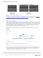
MCM group cabling one, two, or three chassis
Once the MX7000 chassis are assembled into an MCM group, network fabrics, deployment templates,
networks, and other MX7000 management constructs can be used in the deployment and management of
new and existing resources.
2.2 MX7000 Network Fabrics
The MX7000 supports three I/O fabrics. The three fabrics are labeled: A, B, and C. Each fabric consists of a
pair of I/O devices that provide redundant connectivity. The C fabric is unique because it is a storage only
fabric allowing the installation of an MX5000s SAS switch.
Network Fabrics A and B
The MX7000 A and B Fabrics are each made up of two devices to provide both throughput and redundancy.
The network devices are referred to as devices A1 and A2 for the A fabric and B1 and B2 for the B fabric. The
A and B fabrics support Ethernet switches, Ethernet switching engines, fabric expansion modules, storage
fabric switches and pass-through devices. Pass-through devices allow the connection of the internal NIC
ports to external, fixed port switches.
Storage Only C Fabric
The MX7000 C Fabric consists of a pair of Dell EMC PowerEdge M5000s storage switches. These switches
can connect to some number of Dell EMC PowerEdge M5016s storage sleds. The MX5016s storage sleds
can support up to 16 12Gbps SAS drives and these drives can be assigned to individual compute sleds within
the same MX7000.

Error! No text of specified style in document.
8 Scaling VCF Domains Beyond a Single MX7000 Chassis | Document ID
3 Dell Scalable Fabric Architecture
A Scalable Fabric spans multiple chassis and enables them to behave like a single chassis from a networking
perspective. In contrast, an MCM group enables multiple chassis to be managed like a pool of chassis
resources.
A Scalable Fabric consists of two main components - one MX9116n FSE and one MX7116n FEM in each of
the first two chassis, and additional pairs of MX7116n FEMs in the remaining chassis. Each MX7116n FEM
connects to the MX9116n FSE corresponding to its fabric and slot. This hardware-enabled architecture
applies regardless of whether the switch is running in Full Switch or SmartFabric mode. All IOMs participating
in the fabric are configured in either Full Switch or SmartFabric mode.
Each chassis can physically contain two general-purpose network fabrics, A, and B. Each of these fabrics has
two IOM slots available; A1 and A2, and B1 and B2. Each of the A or B fabrics can be configured
independently. You could use Full Switch Mode or SmartFabric for either or both of the A or B network fabrics
in the chassis.
The UI is used to configure the switches SmartFabric mode, and the OS10 CLI is used for switch
configuration in Full Switch mode. Full switch mode offers a granularly configurable method that exposes the
manual configuration of every possible feature of the switch. A switch in SmartFabric mode allows fewer
options but allows configuration parameters to be reused and to be deployed quickly and consistently.
3.1 Full Switch Mode
Full Switch Mode allows the MX9116n FSEs to be manually configured as switches. In Full Switch mode, all
SmartFabric OS10 features and functions that are supported by the hardware are available to the user. In
other words, the switch operates the same way as any other SmartFabric OS10 switch. Configuration is done
using the CLI.
3.2 SmartFabric
SmartFabric allows the creation and deployment of network settings (VLANs, MTU, QoS) to the compute
sleds and creating VLT enabled uplinks to the spine or aggregation layer. SmartFabric contains the following
components:
• Networks
• Fabric
• Uplinks
• Templates
• Deployment
3.2.1 Networks
Networks are defined and identify the VLANs that are to be applied to the ports of the FSEs and any
connected FEMs. Networks can be applied to both the Uplinks and to the ports on the FSE that connect to the
compute sleds. Networks contain:
• Name
• Description
• VLAN ID

Error! No text of specified style in document.
9 Scaling VCF Domains Beyond a Single MX7000 Chassis | Document ID
Networks also contain a Type value that pertains to the QoS settings for the network. There are 11 different
network types available. Some examples are: Storage-iSCSI, Storage-FCoE, VM Migration and Hypervisor
Management. The network type is selected at the time the network is created. Network types can be modified
at any time.
3.2.2 Fabric
Since each chassis can contain both an A and B pair of IOMs a chassis can have one or two fabrics. A fabric
is created on the lead chassis which will contain the switches being deployed. The fabric also defines
whether the switches exist in the same chassis or in two different chassis. Only the FSEs can be deployed in
different chassis and still be part of the same Fabric. The creation of the Fabric causes the FSEs to reboot
into SmartFabric mode. Changing the operational mode and rebooting of the FSEs can take more than 10
minutes. Be patient while the FSEs are reconfigured. Once the Fabric is created, it displays a warning. The
warning indicates that a Fabric has been created but that the Fabric has no Uplink configured.
3.2.3 Uplink
A Fabric runs in an error state which displays: “The SmartFabric is not healthy because at least one uplink
must be configured” until an Uplink is defined. Creation of the Uplink allows the administrator to identify:
• Which FSEs are to be used.
• Which ports of the FSE connect to the upstream network.
• How the selected ports are used (Uplink Type).
• Which networks are assigned to the Uplink.
• How the networks traverse the Uplink (tagged or untagged).
In the case of a single Uplink from the FSE to the upstream network layer ports 1/1/41 and 1/1/42 are typically
used. Select the appropriate Uplink ports for both FSEs. Failure to select both will create a warning indicating
an asymmetric uplink condition.
Once the Uplink ports are selected the administrator selects the Networks to be applied to the Uplink. Each
uplink can have up to one (only one) Untagged Network and zero or more Tagged Networks. The networks
assigned to Uplinks can be updated at any time. SmartFabric applies the networks that are prescribed to both
FSEs in the Fabric. During the creation of the Uplink
The “Uplink Type” support two different Ethernet modes and FCoE, FC Gateway and FC Direct Attach. Only
Ethernet uplinks are addressed in this document. The Uplink Type defines how the connection to the
upstream network will be configured.
Ethernet – No Spanning Tree
“Ethernet – No Spanning Tree” is used when the upstream connection is a physical or virtual Link
Aggregation. When “Ethernet – No Spanning Tree” is selected a VLT LAG is created across both of the
MX9116n IOMs. Since both ends of the connection see the other as a single, aggregated connection there is
no requirement for spanning tree.
Ethernet

Error! No text of specified style in document.
10 Scaling VCF Domains Beyond a Single MX7000 Chassis | Document ID
“Ethernet” is used when there will be multiple, individual (nonaggregated) links to the upstream network. In
this case Spanning Tree protocol is used to prevent loops in the Ethernet fabric that could have catastrophic
results.
The uplink only defines the behavior of the connection from the MX9116n IOMs to the upstream network. The
uplink configuration has no impact on the server facing ports of the IOMs.

Error! No text of specified style in document.
11 Scaling VCF Domains Beyond a Single MX7000 Chassis | Document ID
4 Deployment
Deploying host configuration parameters such as BIOS, iDRAC, RAID, NIC/CNA, and configuring the host
facing switch ports is done through the Deployment process. Deployment involves Templates and the
methods to apply the configuration data
Templates can be deployed in two different ways.
• Attach To Slots
• Deploy To Devices
Template Target Types
Attach to Slots
Templates that are attached to slots allow any compute sled inserted into those slots to take on the
personality of the assigned template. This is useful in a larger cluster where you may replace a host quickly.
Any replacement compute sleds that are inserted into that chassis slot will immediately be reconfigured using
the assigned template.
Deploy to Devices
Templates that are deployed to devices travel with the device (server). Deploying templates to devices is
useful where you expect growth and may move a device to a different slot or chassis. “Deploy to Devices” is
useful for hosts that are limited in numbers but still have specific requirements. VCF Management Domain
hosts or NSX-T Edge Node hosts are examples that might benefit from “Deploy To Devices” deployments.
4.1.1 Templates
A server template contains parameters that are extracted from a server and allows these parameters to be
quickly applied to multiple servers. A server template can contain any or all server settings for a specific
deployment type including BIOS, iDRAC, RAID, NIC/CNA, and so on. The template can be captured from a
reference server and can then be deployed to multiple servers simultaneously. The server template allows an
administrator to associate VLANs to compute sleds.

Error! No text of specified style in document.
12 Scaling VCF Domains Beyond a Single MX7000 Chassis | Document ID
The templates contain settings for the following categories:
• Local access configuration
• Location configuration
• Power configuration
• Chassis network configuration
• Slot configuration
• Setup configuration
Templates are created by building templates from reference servers that have been configured, using one of
the prebuilt templates in the OME-Modular interface or by importing a template that was exported from
another system. Any template can be cloned and edited. Networks can be added and removed to templates.
Deployment Template Configuration Elements
When creating a template from a reference server select a device and the Configuration Elements to be
captured in the template. Deploying a template to a server requires the server to reboot to the Dell LifeCycle
Controller which will apply the captured Configuration Elements to the servers being deployed.
For more information on Templates, see the: Dell EMC PowerEdge MX SmartFabric Configuration and
Troubleshooting Guide.

Error! No text of specified style in document.
13 Scaling VCF Domains Beyond a Single MX7000 Chassis | Document ID
5 Initial VCF Cluster Deployment
When deploying the initial VCF Management Domain and Workload Domain on the first MX7000 consider
growth beyond a single chassis. The choice of the Scalable Fabric Architecture is the fastest and most
reliable path to a successful expansion.
VCF Management and Workload Domains are deployed as clusters. Since the Management Domain cluster
and Workload cluster are currently deployed to a single MX7000, we can treat them similarly. See the Dell
EMC PowerEdge MX SmartFabric Configuration and Troubleshooting Guide for the process of deploying the
Management Domain. The four Management Domain hosts are configured in a vSAN, contain NSX-T Edge
Nodes and are configured for vMotion. Workload Domain hosts may be different than the Management
Domain hosts so a different Template will be created for Management and Workload hosts.
Since redistributing these management hosts across more than one chassis may be desirable in the future,
the compute sleds were deployed using the “Deploy To Devices” method. When the hosts are later moved to
the second MX7000 chassis SmartFabric identifies the ports to which the compute sled is connected and
apply the appropriate network settings. The “Deploy To Devices” method also means that the server
Configuration Elements were already applied and will not be changed on the hosts.
Initially a single MX7000 was deployed with a pair of MX9116n FSEs in the A1 and A2 slots. The FSEs were
configured in a nonspanning tree Ethernet configuration that connected to an LACP-managed LAG on the
upstream network layer. While the MX9116n is capable of Layer 3 routing when configured in Full Switch
Mode it was configured using SmartFabric. In this case, the MX9116n is connected to the upstream network
at Layer 2 and allows the upstream network handle the routing.
Single MX700 with dual MX9116n
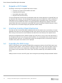
This deployment of two MX9116n FSEs represents the starting point for a recommended design. The two
MX9116n FSEs can be redistributed as additional chassis are added and MX7116n FEMs can be added to
expand the port count of these FSEs. There are several possible configurations that are supported by
different combinations of the FSEs and FEMs. See the latest Dell EMC PowerEdge MX SmartFabric
Configuration and Troubleshooting Guide. All these configurations are designed for scalability of
deployment, management, and network capacity. As per the guide the following restrictions and guidelines
are in place when building a Scalable Fabric:

Error! No text of specified style in document.
14 Scaling VCF Domains Beyond a Single MX7000 Chassis | Document ID
• All MX7000 chassis in the same Scalable Fabric must be in the same Multichassis Group.
• Mixing IOM types in the same Scalable Fabric (for example, MX9116n FSE in fabric slot A1 and
MX5108n in fabric slot A2) is not supported.
• All participating MX9116n FSEs and MX7116n FEMs must be in MX7000 chassis that are part of the
same MCM group. For more information, see the Dell EMC OpenManage Enterprise-Modular Edition
Version 1.20.00 for PowerEdge MX7000 Chassis User's Guide. Find the relevant version of the User
Guide in the OME-M and OS10 compatibility and documentation table.
• When using both Fabric A and B for a Scalable Fabric, the following restrictions apply:
- IOM placement for each fabric must be the same in each chassis. For instance, if an MX9116n
FSE is in chassis 1 fabric slot A1, then the second MX9116n FSE should be in chassis 2 fabric
slot A2.
- For chassis 3 through 10, which only contain MX7116n FEMs, they must connect to the MX9116n
FSE that is in the same group.

Error! No text of specified style in document.
15 Scaling VCF Domains Beyond a Single MX7000 Chassis | Document ID
6 Expand a VCF Cluster
Expanding a cluster beyond a single MX7000 chassis involves.
• Shut down any cluster hosts that will be relocated
• Expanding the MCM group
• Reconfiguring the network fabric
• Bring the hosts and VMs back up
Since the Management Domain cluster and Workload cluster are currently deployed to a single MX7000, you
can treat them the same way. The four Management Domain hosts are configured in a vSAN, contain NSX-T
Edge Nodes and are configured for vMotion. Since distributing these management hosts across more than
one chassis may be desirable in the future, the compute sleds were deployed using “Deploy To Devices”
method. When the hosts are moved to the second MX7000 chassis SmartFabric identifies the ports to which
the compute sled is connected and apply the appropriate network settings.
6.1 Shut Down Existing Virtual Infrastructure
Evacuate any VMs from hosts that will be redistributed from the first chassis to the new chassis(s). It may be
desirable to move two of the four management domain hosts from the first chassis to the second chassis. Any
VMs running on the hosts to be moved should be evacuated to the hosts that stay in the original chassis.
During the reconfiguration process network changes may cause errors to occur on any hosts still running. If
the management domain is not running any other workloads, it is recommended that you shut down the VCF
management stack and hosts. If you decide to shut down the management stack, ensure that you have the
shutdown order specific to the version of VCF deployed.
6.2 Expanding the MCM Group
Before an MCM group can be expanded the MX9002m management modules of the MX7000 chassis must
be properly cabled. Figure 1, above shows the cabling for a single chassis, two chassis and three chassis. A
maximum of 20 chassis can be configured in a single MCM group. The cabling of the MX9002m modules
must continue in the same fashion across all the (up to 20) chassis before they can be added to an MCM
group.
Adding a member chassis to the MCM group is done through the OpenManage Enterprise Modular interface.

Error! No text of specified style in document.
16 Scaling VCF Domains Beyond a Single MX7000 Chassis | Document ID
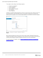
Adding a member chassis
From the Modify Group Members window (on the lead chassis) any other chassis that is properly cabled will
appear in the Available Chassis pane.
1. Select the available chassis
2. Click Add Chassis.
3. Click Finish to complete the process and add the chassis to the MCM group.

Error! No text of specified style in document.
17 Scaling VCF Domains Beyond a Single MX7000 Chassis | Document ID
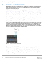
Adding Member Chassis to MCM Group
6.3 Reconfiguring the Network Fabric
Reconfiguration of the network fabric from one to two chassis is carried out by redistributing the MX9116n
FSEs across the two chassis.
The only invasive reconfiguration of the network fabric occurs when the fabric is expanded from a single
chassis to more than one chassis. Adding additional chassis beyond the second chassis has no impact on
workloads already running.
The physical reconfiguration starts with moving one of the MX9116n FSEs to the second chassis and then
adding the appropriate FEMs. In this example The A2 FSE from the first chassis is moved to the A2 slot in the
second chassis. An MX7116n FEM is installed in the now empty A2 slot of the first chassis. Another MX7116n
is added to the second chassis and placed in the empty A1 slot. Cabling the FSEs to their respective FEMs is
made using 200GbE QSFP28-DD cables. A 200GbE connection provides a full 25GbE for each of the eight
possible compute facing ports of the FEMs. These should be cabled as follows:
• The A1 FEM in the second chassis is cabled to the A1 FSE in the first chassis
• The A2 FEM added to the first chassis is cabled to the A2 FSE moved to the second chassis
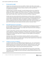
Figure 5 shows the network fabric configuration before and after the redistribution of the FSEs and the
addition of the FEMs. The A1 side of the fabric has its FSE in the first chassis and that the A2 side of the
fabric has its FSE in the second chassis.

Error! No text of specified style in document.
18 Scaling VCF Domains Beyond a Single MX7000 Chassis | Document ID
Scalable Fabric I/O Module Placement
While there are other supported topologies this topology provides complete redundancy. See the Dell EMC
PowerEdge MX SmartFabric Configuration and Troubleshooting Guide for more information about supported
topologies.
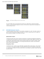
6.3.1 Logical Reconfiguration
With the expansion of the MCM group and the physical reconfiguration of the FSEs and their corresponding
FEMs, the OME-M Network Manager detects the changes to the fabric topology. The fabric is evaluated, and
the fabric topology will be updated. Port mappings of NICs in the compute sleds to ports of either the FSEs or
the FEMs are updated. Previously deployed templates are used to update the configuration of any server
facing ports that may have moved during the reconfiguration.
Figure 8 shows the resulting topology from this reconfiguration as understood by the OME-M Network
Manager.
Updated Topolgy as Updated by the Network Manager
_______________________________________________________________________________
Note: the diagram shows that the FSEs now exist in different chassis. The FEMs are not displayed because
they are just the mechanical implementation of the ports that exist on the FSEs. No action is needed to
reconfigure the uplinks or the VLANs assigned to those uplinks.
_______________________________________________________________________________

Error! No text of specified style in document.
19 Scaling VCF Domains Beyond a Single MX7000 Chassis | Document ID
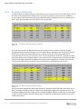
6.3.2 Resulting Port Mappings
Though the physical compute sleds were not moved the ports to which the NICs connect will change. The A2
NIC ports on the compute sled installed in slot 1 of chassis one, before the second chassis is added are
shown in figure 9 below. Note that because both IOMs were initially installed in chassis one, that the hosts in
slots 1 and 2 are connected to Eth 1/1/1 and Eth 1/1/3 on both IOMs
Compute to IOM Ports Before Expansion
Once the second chassis is added and the IOMs are moved (as shown in figure 7 above) the network
manager will update the fabric topology. Part of that update will be to determine the FEM ports to which the
A2 NIC ports of these two compute sleds connect. Keep in mind that the FEMs just provide physical
connections back to the FSE, so ports 1/71/1 and 1/71/2 are actually ports on the FSE. These two compute
sleds were deployed using “Deploy to Device” which means that the configuration elements follow the device
and the VLAN tagging specified in the deployment template will be applied to the A2 ports now connected.
This shows the ports to which the A2 NICs are connected after the reconfiguration of the Fabric.
Compute to IOM Ports After Expansion
If the servers were deployed using the “Deploy to Device” method the OME-M will detect the location of the
device and apply the settings that are contained in the deployment template to the appropriate ports. If the
servers were deployed using the “Deploy to Slot” method the OME-M detects the ports that are now mapped
to that slot. OME-M will then apply the settings that are contained in the deployment template to any server
installed into that slot.

Error! No text of specified style in document.
20 Scaling VCF Domains Beyond a Single MX7000 Chassis | Document ID
If, for example, you moved management domain hosts 3 and 4 to slots 1 and 2 of the new chassis the OME-
M software would reconfigure the ports that are connected to new locations of those servers.
6.4 Restart Hosts and VMs
Now that all the NIC ports and their corresponding FSE and or FEM ports have been reconfigured based on
their location any hosts that were shut down can be brought back up. Any stopped VMs that were not
evacuated to another host can be restarted.
If the VCF management domain VMs were shut down be sure to check the latest VMware documentation for
starting a stopped management domain.
Page is loading ...
-
 1
1
-
 2
2
-
 3
3
-
 4
4
-
 5
5
-
 6
6
-
 7
7
-
 8
8
-
 9
9
-
 10
10
-
 11
11
-
 12
12
-
 13
13
-
 14
14
-
 15
15
-
 16
16
-
 17
17
-
 18
18
-
 19
19
-
 20
20
-
 21
21


Dell Servers Solution Resources Owner's manual
- Type
- Owner's manual
- This manual is also suitable for
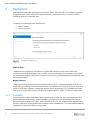
Ask a question and I''ll find the answer in the document
Finding information in a document is now easier with AI
Related papers
-
Dell Servers Solution Resources Owner's manual
-
Dell PowerEdge MX7000 User guide
-
-
-
-
-
-
-
-