Page is loading ...

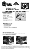
Part #575 with controls
Part #580 with out controls
CJ Electric Fan
Custom Fits 1973-1986 6 & 8 cyl.
Installation Instructions
10-06-08 99751 Page 1 of 3
DIAGRAM A
Washer
Screw
Mounting Bolt
Radiator Channel
Mounting Bracket
Mounting Bracket
Mounting Bolt
Washer
Washer
Washer
Screw
Screw
Screw
(SEE DIAGRAM A)
Step 1: Remove the existing fan and
clutch assembly.
Step 2: Replace the bolts that mount-
ed the fan assembly to the pulley.
When reinstalling the bolts it may
be necessary to use washers to
‘shim’ out the bolt for clearance on
the back of the water pump drive.
Be sure to tighten these pulley
bolts.
Step 3: Remove the stock radiator
shroud assembly, be sure to save
the mounting bolts. These bolts
will be used to mount your new
Flex-a-lite fan.
Step 4: Attach the mounting brack-
ets to the Flex-a-lite fan shroud
with screws and washers pro-
vided. The end of the mounting
bracket with two holes should
be at the top of the shroud. (See
Diagram A)
Step 5: Lower the fan/bracket assembly into the engine bay, and attach to radiator using the
original shroud bolts.
Step 6: Check for clearance between the fan and any moving components within the engine
bay and make sure the fan blades turn freely and do not contact the radiator.
MANUAL FAN DISCONNECT:
To turn off your fan before a water crossing or other reason, place a Flex-a-lite #31148 Manual Switch
between the ‘+’ terminal and the 12V source. This switch will turn the thermostat control to the fan off,
when the switch is off to prevent the fan from running automatically.
Make sure that you do not have a manual switch wired to the ‘M’ terminal and that the AC is off
or manual switch is turned off.

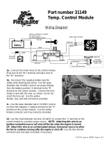
Fan Wiring Instructions
Step 1: Locate mounting point for control
Locate a mounting point for control near inlet side of radiator. Control needs to be placed within 18"
of radiator inlet hose. You may want to mount next to radiator on fender well. Mount control using
screws provided.
Step 2: Wire the fan motors (refer to Wiring Diagram, below)
Using the bullet connectors provided, attach a length of the large diameter (12 AWG) red wire to the
colored motor wires at fan. Attach a length of the large diameter (12 AWG) black wire to the black
motor wires at the fan. Once the fan is in place, these will attach to the control module. If mounting
the control somewhere in the engine compartment, leave enough wire to reach the control module,
but do not connect yet.
Step 3: Connect the motor wires to the control module using supplied female connectors
(Red wire to the "M+" terminal and black wire to the "M-" terminal).
Step 4: Disconnect the negative battery lead for safety while finishing the wiring. Use the large
diameter red wire to run power directly from the battery positive (+) terminal to the "B" terminal on the
control module. Connect the fuse holder in-line with this wire, as shown, but do not insert the fuse
yet. Use the blue female, ring, and butt connectors provided.
Step 5: Use the large diameter black (12 AWG) wire to run from the negative (-) battery terminal to
the "G" terminal on the control module. Use the blue female connector and ring connector provided.
Step 6: Use the small diameter red wire (14 AWG) to connect the "+" terminal on the control module
to a positive power source. NOTE: Attaching this wire to an ignition-controlled source will shut
off the fan when the engine is turned off. Attach this wire to an uninterrupted (always hot)
power source to allow the fan to continue running after the engine is shut off. Use the blue
female connector and fuse taps (included) if necessary.
Step 7: (Optional) For air conditioning control (if desired) connect the "C" terminal on the control
module to the positive wire that triggers the A/C compressor using the small diameter green (14
AWG) wire. Using a voltmeter, determine which wire coming from the compressor is the positive trig-
ger wire. Use the 3-way connector (included) to tap into this wire and send a signal to the fan control
module. The fan will cycle on and off with the A/C clutch when the A/C is turned on.
10-06-08 99751 Page 2 of 3
Colored

10-06-08 99751 Page 3 of 3
Step 8: (Optional) For manual switch operation, use Flex-a-lite p/n 31148. Connect the switch as
shown on the wiring diagram (previous page). Connect the "M" terminal on the control module to the
"1" terminal on the switch. Connect the "2" terminal on the switch to a positive 12v power source.
Connect terminal "3" on the switch to a good ground (for switch illumination). NOTE: To prevent
thermostatic activation (if only manual switch operation is desired), omit the lead to the "+"
terminal of the control box. "B", "G", "M+" and "M-" must remain connected. If not using a
Flex-a-lite manual switch, do not connect a ground wire to the switch!
Step 9: Use the zip ties provided to secure the wires and prevent them from interfering with fan
blades, belts, and pulleys in the engine compartment. Reconnect the battery and insert the 30 amp
fuse provided.
Step 10: Insert the temperature probe into the radiator fins
Install temp. probe near inlet hose... then install the insulator cap.
Locate the inlet hose from the engine to the radiator. Remove the black insulator cap and insert the
temp. probe through the radiator fins near the inlet hose. Reinstall the black insulator cap.
If you disconnected any hoses or drained coolant to install the fan, reconnect the hoses and refill
the radiator. Press the control knob (included in wiring kit) onto the control box shaft. Turn the knob
clockwise until it stops. Start the engine and allow it to idle. Using a digital thermometer (positioned
near the inlet hose) or the vehicle's temperature gauge, monitor the temperature. When the coolant
temp. is slightly above normal (or desired temp.), turn the knob counter-clockwise just until the fan
turns on. From now on, the fan should activate at this temperature setting. Adjust as necessary to
maintain desired temperature.
Step 11: Adjust the temperature control knob on the control box
The Flex-a-lite Limited Warranty
Flex-a-lite Consolidated, 7213-45th St. Ct. E. Fife, WA 98424, Telephone No. 253-922-2700, warrants to the original purchasing user, that all Flex-a-lite products to be free of defects in material and
workmanship for a period of 365 days (1 year) from date of purchase. Flex-a-lite products failing within 365 days (1 year) from date of purchase may be returned to the factory through the point of
purchase, transportation charges prepaid. If, on inspection, cause of failure is determined to be defective material or workmanship and not by misuse, accidental or improper installation, Flex-a-lite
will replace the product free of charge, transportation prepaid. Flex-a-lite will not be liable for incidental, progressive or consequential damages. Some states do not allow the exclusion or
limitation of incidental or consequential damages, so the above limitation or exclusion may not apply to you. This warranty gives you specific legal rights and you may have other rights, which vary
from state to state. The Flex-a-lite warranty is in compliance with the Magnuson-Moss Warranty Act of 1975.
/