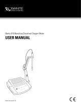
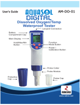
Omega DOH-10-Series_DO_Meter Owner's manual

Category
Measuring, testing & control
Type
Owner's manual

This manual is also suitable for

Omega DOH-10-Series_DO_Meter is a professional-looking portable meter with a large LCD display. It is designed with a BNC connector compatible with any DO galvanic electrode. The meter has a hold function, power capacity icon indicator, and automatic power-off in 15 minutes (which can be disabled). It also includes an RFS (Recover to Factory Setting) function. With built-in different temperature compensation selectable (Thermistor 30K, 10K ohm, and manual 25.

Omega DOH-10-Series_DO_Meter is a professional-looking portable meter with a large LCD display. It is designed with a BNC connector compatible with any DO galvanic electrode. The meter has a hold function, power capacity icon indicator, and automatic power-off in 15 minutes (which can be disabled). It also includes an RFS (Recover to Factory Setting) function. With built-in different temperature compensation selectable (Thermistor 30K, 10K ohm, and manual 25.

User’s Guide
Shop online at
omega.com
e-mail: inf[email protected]om
For latest product manuals:
omega.com/en-us/pdf-manuals
DOH-10
Series
Handheld Dissolved Oxygen Meter Kit with
Optional SD Card Data Logger
TM
2
omega.com info@omega.com
Servicing North America:
U.S.A. Omega Engineering, Inc.
Headquarters: Toll-Free: 1-800-826-6342 (USA & Canada only)
Customer Service: 1-800-622-2378 (USA & Canada only)
Engineering Service: 1-800-872-9436 (USA & Canada only)
Tel: (203) 359-1660 Fax: (203) 359-7700
For Other Locations Visit omega.com/worldwide
The information contained in this document is believed to be correct, but OMEGA accepts no liability for any errors it contains, and
reserves the right to alter specifications without notice.
1
Professional look design portable meters with large LCD display,
Meter is designed with BNC connector compatible to any DO galvanic electrode.
Hold function, power capacity icon indicator, and automatic power off in 15 minutes and
may disable.
RFS (Recover to Factory Setting) function is included.
Built-in different temperature compensation selectable: Thermistor 30K, 10K ohm and not
25.0 (manual compensation).
DO 100% air self-calibration is convenient and simple. (Calibrated both Saturated DO / zero
DO (Na
2
SO
3
) before shipment)
Compact DO electrodes supplied with 3M cable and membrane cap, electrolyte.
Galvanic electrodes do not require long "warm up" time as polarographic type electrodes (Polarization is required
about 10-15 minutes).
Applications: Aquariums, Bio-reactions, Environmental testing (lakes, streams, oceans), Water / Wastewater
treatment, Wine production
Tripod receptacle mountable design for long time monitoring purposes.
1. Meter
2. Battery-AAA x 3 pcs
3. Electrode x 1pcs (DO Galvanic type)
4. Black carrying case
5. Electrolyte (0.5M NaOH) x1
6. Membrane cap x 1
7. Membrane x 10pcs
8. Red sandpaper (for polishing DO electrode)
9. 8G SD card (DOH-10-DL only)
10. Calibration certificate
Membrane
Model
DOH-10 DOH-10-DL
Data Hold Freeze the display readings.
Meter dimension 175mm x 58mm x 32mm (With BNC connector)
Power supply AAA batteries x 3 pcs / 9V AC/DC (Option)
Parameter DO, temperature
SD sampling time
Setting range
N/A
Auto
2 secs, 5 secs, 10 secs, 15 secs, 30
secs, 60 secs, 120 secs, 300secs, 600
secs, 900 secs, 1800secs, 1Hr
Manual
Manual Sample time: 0 second
Press the ADJ button once will save
data one time. @Set the sampling
time to 0 second.
Memory Card N/A SD memory size 8G
GENERAL SPECIFICATION:
SUPPLIED:
FEATURES:
11. AQM-100-PW - AC Adapter
(Optional, Sold separately)
2
BUTTON DESCRIPTION:
ELECTRODE INSTALLATION (BNC connector):
Temperature
0~90
Temp. accuracy
±0.5
Measurement range
0~199.9% (In saturation); 0.0~20.0 mg/L
Accuracy
±2% of full scale + 1 digit
Resolution
0.1%, 0.1 mg/L
Calibration
100% Air-Saturated
Flow condition
0.3 mL/s
Dimension
12x120mm
Electrode body
ABS
Sensor type
Galvanic
ATC Temp. sensor probe
port
3.5 Ø mm diameter phone jack (10K ohm resistance)
Cable length
3 M
PWR
Power on (Press in one second) or power off (Press more than 2 seconds when
operation)
SET
Long press to enter/escape salinity/pressure setting.
Move to left digit. (Under setting mode).
Long press to save setting or calibrate the reading.
CAL
Move to right digit. (Under setting mode).
MODE
Short press to change DO unit (mg/L or %).
Short press to enter pressure setting. (Under salinity setting mode.)
UNIT
Short press to change temperature unit /.
Long press to enter temperature electrode type selection.
Short press to select NTC: Negative Temperature Coefficient)/ NOT: no remote
temperature electrode.
Long press to save setting.
HOLD
Freeze current readings (Hold icon shows at top of LCD).
Increase value. (Under setting mode).
ADJ
Decrease value. (Under setting mode).
MODE+CAL
Long press to enter DO 100% or zero calibration mode.
(Na
2
SO
3
is required).
SET+UNIT
Recover to factory setting (under DO calibration mode).
HOLD+PWR
Disable Auto Power Off.
1. Insert the DO electrode into the top of right hole. And insert the 3.5mm Ø diameter phone jack ATC sensor plug
into the middle hole.
2. Hold the BNC connector in one hand; with the other, insert the braid into the center of the connector. Continuing
pushing the braid into the connector until it will not go in any farther.
Do this gently and slowly; do not bend the braid.
3. Turn the male BNC connector in a clockwise direction, until you cannot turn it any more.
DO ELECTRODE SPECIFICATION:
3
POWER:
TEMPERATURE COMPENSATION SENSOR TYPE SELECTION:
Power supply:
1. AAA batteries x 3pcs.
Battery icon indicates when power is weak, replace with new batteries immediately as the readings now on
LCD are incorrect due to weak power.
Battery life: Approx. 480 hours for continuous used. .
2. Make sure electrode and meter are well connected. Don’t attempt to detach electrode from meter while in operation.
3. When meter shows erratic readings, it must be sensor failed or power is weak or calibration is required.
4. Only select one of the two electrodes while measuring the same water zone, otherwise meter appears erratic
readings. Read two parameters at the same time are only available for measuring two different water sources.
NOTE: Make sure you have connected the electrode to the meter before power on.
Momentarily press PWR button to turn on the meter, press and hold PWR button to turn off meter.
NOTE:
For each operation, make sure you are using fresh batteries, same brand, same power of batteries is also required,
otherwise ,LCD shows erratic readings and leakage may occur. Warranty is void if not follow the notices. (Note
Remove batteries when not use)
Power-off switch: When the meter is turned off, the internal CPU does not shut down completely, it will keep detecting
the buttons per milliseconds. Letting meter know if the user wants to activate the meter or not. It will consume the
power by each detecting, in order to save the power, you may pull down the switch.
Pull down
The switch
NOTE: Default setting is NTC 10K ohm.
There are two fixed 10Kohm and 30Kohm temperature compensation sensors for selection.
NTC 10K:
Negative Temperature Coefficient 25 = 10 K ohm
NTC 30K: Negative Temperature Coefficient 25 = 30 K ohm
NOTE:
External temperature electrode is excluded, user can enter the temperature value by their own
temperature instrument, default temperature is 25 ,adjustable range is : 0.0~90.0
Step 1: Must select correct electrode type before measurement, otherwise the value would be incorrect.
Step 2: Long press UNIT button, the meter default is ntc 10k, short press UNIT button to toggle ntc 30k not.
Step 3: Long press UNIT button again to save the setting, meter shows SA” at the bottom of LCD and then
return to normal measurement mode.
4
DO (Dissolved Oxygen) CALIBRATION:
Protective cap
Electrode type
ntc 10K (Default)
ntc 30K
not
Plug in
Temp. XX.X
Temp. XX.X
Manual temp.
Un-plugged
ATC icon
O
O
X
Calibration is necessary before measurement, please refer to the following calibration procedures:
A) Required Equipment:
1) DO electrode.
2) Sodium sulfite (Na2SO3) solution (For 0% DO calibration used).
3) Mini motor / pump in water or air bubbler or magnetic stirrer platform (For 100% Air-Saturated Water Calibration
used).
B) DO electrode installation:
NOTE: DO NOT touch the sensitive membrane when using the electrode or replacing the membrane cap,
for the sweat and grease will affect the quality of membrane and decrease the rate of oxygen permeability.
1) Remove protective cap from DO sensor head.
2) Loose the membrane cap and remove it.
NOTE: We will provide 1 pc membrane cap with membrane (pic.1), if you are first time to use the membrane cap,
please skip step 2) and follow step 7) to filling in DO electrolyte solution. If you want to change membrane, please
loose the membrane cap and remove it as pic. 2. Then follow step 3) to clean the membrane cap.
Pic. 1
Pic.2
“ATC” ICON INDICATION
5
3) Rinse the Membrane Module with distilled water and blot dry with a clean lab wipe.
4) Clip one membrane from white protective round paper.
5) May use tweezers to put the membrane between the membrane cap and membrane base. (See the below
picture)
6) Push the membrane cap downward gently until it won’t lose.
7) Fill the membrane cap with the DO electrolyte solution 0.5M NaOH provided. Some solution will be vented from the
overflow port. This is normal. It should be completely filled. After injecting the solution, screw the Membrane
module. Finger-tighten until snug. Do not over tighten.
8) After injected the solution, screw the Membrane Module. Finger-tighten until snug. Do not over tighten.
membrane
6
9) After filling the electrolyte solution and screw the membrane cap, please find the insulation tape to seal the
seam of the sensor head to reduce solution leakage, please refer to the picture below:
Insulation tape
10) Check the membrane module to see whether there are air bubbles in it. If found there are air bubbles, knock on the
membrane cap carefully to dispel them.
11) Inspect the membrane to ensure that the inner cathode element contacts the membrane. The membrane must be
taut, without wrinkles or imperfections. <If wrinkles are found, please follow 2) to change the membrane.
12) Connect DO electrode with Meter DO BNC connector.
13) Rinse the assembled electrode with distilled water and blot dry with a clean lab wipe.
C) DO calibration C-1) or C-2) or C-3) :
There are three ways to do the DO calibration, for common and convenient way, follow c-1.
For more accurate measurement, follow c-2 and c-3 with necessary devices and solution in laboratories.
NOTE: First doing zero DO calibration and then doing 100% air-saturated water calibration.
C-1) 100% Water-Saturated Air Calibration: (Convenient for self-calibration, common used)
1) Connect the electrode to the meter.
2) By positioning the sensor in air-saturated water (air is directed through water until the water is saturated
with it). The illustration below is a representation of the conditions in air- saturated water.
3) Press and hold MODE+CAL buttons to enter calibration mode, screen shows “DO %100” then press and hold
SET button to save and screen shows SAto complete calibration. Press and hold MODE+CAL buttons, screen
shows ESCmomentarily and return to normal measurement mode.
7
SALINITY CORRECTION
BAROMETRIC PRESSURE SETTING:
C-2) Zero Dissolved Oxygen Calibration: (Laboratory calibration with Na
2
SO
3
powder)
NOTE: Generally need to do zero oxygen calibration in the situation of replacing
new electrode, replacing membrane cap, and long time without using. To do zero dissolved
oxygen calibration by the following steps:
1) Connect the electrode to the meter.
2)
Use the beaker by dissolving approximately 10 grams of Na
2
SO
3
in 500 ml of
distilled water.
3)
Place the electrode in the Na
2
SO
3
solution and wait for the reading to stabilize,
press and hold MODE+CAL buttons to enter calibration mode, press MODE+ADJ+UNIT buttons
again to enter DO %0.0mode, then press and hold SET button to save and screen shows SA” to complete
calibration.
Press and hold MODE+CAL buttons, screen shows “ESC momentarily and return to normal measurement
mode
C-3) 100% Air-Saturated Water Calibration: (Laboratory calibration with stirrer)
1) Connect the electrode to the meter.
2) Pour 100ml deionized water into a 150mL beaker. Use an air bubbler or some
type of aerator to bubble air through the water while stirring for 20 minutes until
the water becomes completely saturated with air.
3) Place the electrode in the air-saturated water and wait for the reading to stabilize,
press and hold MODE+CAL buttons to enter calibration mode, screen showsDO %100”, then press and hold SET
button to save and screen showsSA” to complete calibration. Press and hold MODE+CAL buttons, screen shows
“ESC” momentarily and return to normal measurement mode.
Due to the solution contains significant concentration of salinity affects the read out values of DO.
Thus, to correct salinity value is required in order to get the accurate DO reading.
(Refer to page 8, CHART 1. for reference). Use a salinity meter to get the salt concentration reading.
1) To enter the known salinity value by long press SET button and the screen shows SAL”.
HOLD: ↑to increase ADJ: ↓to decrease
SET: to left digit CAL: to right digit
Adjustable range is 0 to 45.2 ppt.
2) After setting completed, press and hold MODE button to save setting, screen shows SA
to complete setting. To escape the setting by press and hold SET button, screen shows
ESC and return to normal measurement mode.
If you are performing measurements at an altitude different from sea level 760 mmhg
(default value). It is important to enter correct barometric pressure as barometric
pressure affects DO values. (Refer to page 9, CHART 2. for reference)
1) To enter the known pressure value by long press SET button and the screen shows SAL”.
Then, press MODE button again to switch to the pressure setting mode, screen
showsP”.
HOLD: ↑to increase ADJ: ↓to decrease
8
DO MEASUREMENT
FREEZE READINGS:
CHANGE DO UNIT to mg/L or %:
CHANGE TEMPERATURE UNIT to or :
AUTO POWER OFF:
RECOVER FACTORY SETTING
SET: to left digit CAL: to right digit
Adjustable range is 400 to 850 mmHg.
2) After setting completed, press and hold MODE button to save setting, screen shows “SA” to
complete setting. To escape the setting by press and hold SET button, screen shows ESCand
return to normal measurement mode.
1) M
ake sure that the electrode has been calibrated.
2) Immerse the tip of the electrode in the sample to be tested. And wait for the reading to stabilize.
3) The Dissolved Oxygen value (in mg/L or %) is displayed on the second tier of LCD and the temperature reading is
displayed on the third tier of LCD.
NOTE:
For accurate Dissolved Oxygen measurements, stir the electrode while measuring under static solution is required.
This is to ensure that the oxygen-depleted membrane surface is constantly replenished.
A moving stream will provide adequate circulation.
Freeze the current readings of DO and temperature readings by press HOLD button, then iconHoldwill appear on the
top left of screen.
Short press MODE button to toggle mg/L or %.
Short press UNIT button to toggle or .
Meter will turn off automatically in 15 minutes when no use, to disable auto power off function by pressing HOLD and
PWR buttons, “n” momentarily shows on screen, now meter is at non-sleep mode, then turns to normal measurement,
Meter default auto power off.
Recover factory setting is required at the situation of replacing with a new electrode. Strongly recommend to do RFS
function under both DO100% and Zero % modes. See below steps:
Step 1:
Long press MODE+CAL buttons to enter DO 100% , by pressing and holding SET+UNIT buttons, screen will showrFS
momentarily, screen turns to normal measurement mode.
Step 2:
Long press MODE+CAL buttons by passing DO100%, press MODE button to enter zero % mode, by pressing and holding
SET+UNIT buttons, screen will show rFSmomentarily, screen turns to normal measurement mode.
9
CHART 2. Calibration Values for Various Atmospheric Pressures and Altitudes
Temp.
Salinity (ppt)
Temp.
Salinity (ppt)
0
ppt
9.0
ppt
18.1
ppt
27.1
ppt
36.1
ppt
45.2
ppt
0
ppt
9.0
ppt
18.1
ppt
27.1
ppt
36.1
ppt
45.2
ppt
0.0
14.62
13.73
12.89
12.1
11.36
10.66
26.0
8.11
7.71
7.33
6.96
6.62
6.28
1.0
14.22
13.36
12.55
11.78
11.07
10.39
27.0
7.97
7.58
7.2
6.85
6.51
6.18
2.0
13.83
13
12.22
11.48
10.79
10.14
28.0
7.83
7.44
7.08
6.73
6.4
6.09
3.0
13.46
12.66
11.91
11.2
10.53
9.9
29.0
7.69
7.32
6.96
6.62
6.3
5.99
4.0
13.11
12.34
11.61
10.92
10.27
9.66
30.0
7.56
7.19
6.85
6.51
6.2
5.9
5.0
12.77
12.02
11.32
10.66
10.03
9.44
31.0
7.43
7.07
6.73
6.41
6.1
5.81
6.0
12.45
11.73
11.05
10.4
9.8
9.23
32.0
7.31
6.96
6.62
6.31
6.01
5.72
7.0
12.14
11.44
10.78
10.16
9.58
9.02
33.0
7.18
6.84
6.52
6.21
5.91
5.63
8.0
11.84
11.17
10.53
9.93
9.36
8.83
34.0
7.07
6.73
6.42
6.11
5.82
5.55
9.0
11.56
10.91
10.29
9.71
9.16
8.64
35.0
6.95
6.62
6.31
6.02
5.73
5.46
10.0
11.29
10.66
10.06
9.49
8.96
8.45
36.0
6.84
6.52
6.22
5.93
5.65
5.38
11.0
11.03
10.42
9.84
9.29
8.77
8.28
37.0
6.73
6.42
6.12
5.84
5.56
5.31
12.0
10.78
10.18
9.62
9.09
8.59
8.11
38.0
6.62
6.32
6.03
5.75
5.48
5.23
13.0
10.54
9.96
9.42
8.9
8.41
7.95
39.0
6.52
6.22
5.98
5.66
5.4
5.15
14.0
10.31
9.75
9.22
8.72
8.24
7.79
40.0
6.41
6.12
5.84
5.58
5.32
5.08
15.0
10.08
9.54
9.03
8.54
8.08
7.64
41.0
6.31
6.03
5.75
5.49
5.24
5.01
16.0
9.87
9.34
8.84
8.37
7.92
7.5
42.0
6.21
5.93
5.67
5.41
5.17
4.93
17.0
9.67
9.15
8.67
8.21
7.77
7.36
43.0
6.12
5.84
5.58
5.33
5.09
4.86
18.0
9.47
8.97
8.5
8.05
7.62
7.22
44.0
6.02
5.75
5.5
5.25
5.02
4.79
19.0
9.28
8.79
8.33
7.9
7.48
7.09
45.0
5.93
5.67
5.41
5.17
4.94
4.72
20.0
9.09
8.62
8.17
7.75
7.35
6.96
46.0
5.83
5.57
5.33
5.09
4.87
4.65
21.0
8.92
8.46
8.02
7.61
7.21
6.84
47.0
5.74
5.49
5.25
5.02
4.80
4.58
22.0
8.74
8.3
7.87
7.47
7.09
6.72
48.0
5.65
5.40
5.17
4.94
4.73
4.52
23.0
8.58
8.14
7.73
7.34
6.96
6.61
49.0
5.56
5.32
5.09
4.87
4.66
4.45
24.0
8.42
7.99
7.59
7.21
6.84
6.5
50.0
5.47
5.24
5.01
4.79
4.59
4.39
25.0
8.26
7.85
7.46
7.08
6.72
6.39
Altitude
Pressure
DO
Altitude
Pressure
DO
Feet
meters
mmHg
%
Feet
meters
mmHg
%
0
0
760
100
5391
1643
623
82
278
85
752
99
5717
1743
616
81
558
170
745
98
6047
1843
608
80
841
256
737
97
6381
1945
600
79
1126
343
730
96
6717
2047
593
78
1413
431
722
95
7058
2151
585
77
1703
519
714
94
7401
2256
578
76
1995
608
707
93
7749
2362
570
75
2290
698
699
92
8100
2469
562
74
2587
789
692
91
8455
2577
555
73
2887
880
684
90
8815
2687
547
72
3190
972
676
89
9178
2797
540
71
3496
1066
669
88
9545
2909
532
70
3804
1160
661
87
9917
3023
524
69
4115
1254
654
86
10293
3137
517
68
4430
1350
646
85
10673
3253
509
67
4747
1447
638
84
11058
3371
502
66
5067
1544
631
83
CHART 1. Solubility of Oxygen (mg/L) in Water Exposed to Water-Saturated Air at 760 mmHg Pressure
10
SD CARD DATALOGGING
SD Card Information
a) Insert an SD card (8G supplied) into the SD card slot at the side of the meter. SD card must be placed with the front of
the card (label side) facing toward the front of the meter.
Once SD card is inserted properly, icon “SDwill appear on the right of screen.
b) If the SD card is being used for the first time, it is recommended that the card must be formatted.
S
D Card Formatting
NOTE:
Always make sure that the device is compatible with the SD, SDHC or SDXC memory card before
formatting.
WARNING: Backup all your data before formatting. Formatting will erase all data on the memory device.
a) Activate Windows
Click the Start or Windows menu and select Computer (Windows Vista/7) or My Computer (Windows XP).
For Windows 8 users, type “computer” and click the Computer icon in the Apps search results. For
Windows 10, open the File Explorer. Then find “This PC”.
b) Find your SD card.
The removable drive that appears last in the "Devices with Removable Storage" list should be the SD
card that you just connected to your computer. Right-click on your SD card to bring up the right-click menu
options.
Select Format. Keep Capacity” and “Allocation unit size” set to be default.
c) Select the file system.
This is the way that files are stored on the card. Different systems
use different file structures. In order for the SD card to be read
by cameras, phones, printers, Windows, Mac, and Linux
computers, and more.
1. Select Quick Format.
2. Click “Start”.
3. Once the formatting is complete, you can close the window.
AUTOMATIC DATALOGGING
The meter stores a reading at a user-selected sampling rate onto an SD memory card.
The meter defaults to a sampling rate of 2 seconds.
NOTE 1: The sampling rate cannot be “0 for automatic datalogging.
NOTE 2: It is recommended that plug in the adaptor for long time using in order
to avoid data lost. (Adaptor is optional.)
a) Setting the datalogger clock time
NOTE: Make sure the clock of the meter is set up correctly in order to get accurate
date/time during datalogging sessions.
1. P
ower off the meter, press MODE+POWER buttons to enter setting. YEAR digit “17” will flash.
2. Short press CAL button go to MonthDay Hour Minute setting.
3. Press and hold SET button to save setting and screen will show “SAthen “End
.
11
4. Re-power on the meter to back to normal measurement mode.
NOTE: To escape setting by turning off the meter without any change.
b) Setting the datalogger sampling rate
1. While meter is power on, press and hold MODE button to enter setting.
2. Press HOLD button to increase the value ; press ADJ button to decrease the
value.
3. Long press MODE button to save setting.
4. The available settings are: 2 sec, 5 sec, 10 sec, 15 sec, 30 sec, 60 sec, 120 sec, 300 sec, 600 sec, 900 sec, 1800 sec, and
1hr.
c) St
art datalogging
Warning: SD recording the selected temperature unit (or). If changing the temperature unit
during the datalogging sessions, the recorded data will be switched into the selected temperature unit.
1. After inserting the SD card, display will show icon “Logging” on the bottom of the screen.
2. Long press ADJ button to starts recording until icon Logging” flashing on the bottom of screen.
3. When “-Sd-” disappear, SD stop to record data or SD card is not being inserted.
4. When an SD card is used for the first time ,a folder is created on the card and named with the model number. Under
the MODEL number folder, the MODEL number and AUTO+YEAR folder will be automatically created. e.g.:
/DOH-10/AUTO2017/…..
5. When starts
datalogging, a new folder named M(month)/D(date)/H(hour)/M(minute) is created on the SD card in the
AUTO+YEAR folder. At the same time, a new spreadsheet document (CSV.) named M/D/H/M is also created under its
folder.
e.g.: /DOH-10/AUTO2017/04051858/04051858.csv
6. Each CSV. file can be stored up to 30,000 points.
Once 30,000 points are stored, a new file name will be auto created as M/D/H/M right after the last recording time.
Unless you interrupt recording, this process continues in the initial created M/D/H/M folder.
e.g.: /DOH-10/AUTO2017/12261858/12262005.csv
NOTE1: Datalogging stopped when replacing the electrode or removing the SD card or resetting the
sampling rate.
NOTE2: When the recording is been stopped, a new folder will be created as M/D/H/M from the next datalogging.
NOTE3: When the recording year and model number is changed, the new folder will be also created
accordingly.
Month
Date
Hour
Minute
12
MANUAL DATALOGGING (MAX 199 POINTS)
1. Set the sampling rate to “0” (Refer to “Setting the datalogger sampling rate”).
2. In the manual mode, data is logged when press and hold ADJ button and screen shows recorded points “00X” in the
temp. block with icon “MEM” flash in few seconds.
e.g. Recorded 1st point, then bottom screen shows “001”.
3. Lo
ng press CAL button to clear data (Removed MANUAL.csv), screen shows “CLr”.
NOTE 1: While screen shows “Err” by long pressing CAL button, it stands for no data can be cleared or
SD card isn’t being inserted.
NOTE 2: Once clear the data by long press CAL, there is no way to recover the data. If you want to
keep the previous data, rename the fileMANUAL.csv in /DOH-10/ MANUAL.csv is required.
4. Data directory in SD card : /DOH-10/ MANUAL.csv
N
OTE : When manual data records full (199 points), logging will continue, but with new data overwriting
old. If you want to keep the previous data, rename the file MANUAL.csv” in /DOH-10/ MANUAL.csv is required.
TRANSFERRING SD DATA TO PC
a) Remove SD card from the meter.
b) Insert SD card directly into a PC SD card slot or use a SD card reader.
c) Open the saved documents (CSV.) (Data stored) in the folder from PC.
d) File name /Product number/ Sample rate/ Recording point/ Start recording time/ End recording time/ Recording
date/time /Recording parameters will be shown in the CSV. file.
e) Data show “-49” stands for no measured value during recording period.
Manual Datalogging
Auto Datalogging
13
DO reading accuracy improvements
DO (Dissolved Oxygen Galvanic type) ELECTRODE MAINTENANCE
ERROR CODES
If the electrode reading is not at (or very close to) zero in oxygen-free Dl water, then polish the tip (cathode) of the
electrode. If the electrode readings are not within the normal ranges given above, or the electrode reading drifts,
inspect the Membrane Module. If it is visibly torn, punctured, or fouled, replace the Membrane Module. Then follow
the Electrode Preparation procedure. If the electrode response is still outside the normal range after this procedure,
please contact the manufacturer's technical service department.
Some considerations to get accurate measurements with your DO electrode include:
DO measurements are very dependent on barometric pressure, temperature and salinity factors. If your meter allows
for inputs on these factors, make sure you use them correctly and accurately.
Replace the DO electrolyte and calibrate the DO electrode when your measurements seem to be drifting, or
inaccurate.
Replace the Membrane Module if it becomes fouled by the sample, or if it gets torn or punctured.
Follow the Electrode Storage procedure to get the best life from your DO electrode.
Proper maintenance ensures faster measurements, improve accuracy and may extend the lifetime of
the electrodes.
When not in useLong term
For long term storage or to take the electrode out of service, disconnect the electrode from the meter.
Disassemble the electrode membrane cap. Rinse the anode, cathode and membrane cap assembly with distilled
water. Blot the anode and cathode elements with a clean lab wipe.
Shake the membrane cap assembly to expel the DI water. The Membrane Module should be stored WITHOUT
0.5M NaoH electrolyte to prevent the galvanic depletion of the electrode’s anode.
Thread the membrane cap assembly loosely onto the body of the electrode. Do not tighten.
Place the electrode in the box, away from direct sunlight.
When not in useShort term(Over night or the weekend)
The DO electrode should be stored in DI water to prevent electrolyte evaporation.
It is better to disconnect the galvanic DO electrode from the meter when not in use.
P
robe head replacement:
When electrode response time to be longer and displaying value appear obviously error, or when sensitive
membrane of DO electrode has a wrinkle, crack or damaged, should replace a membrane.
Q1: Wrong temperature
A1: Refer to page 3 (TEMPERATURE ELECTRODE TYPE SELECTION), you must use the correct temperature sensor type
or adjust temperature manually (Long press UNIT button then press UNIT to selectnot”).
Q2: Meter shows erratic readings
A2: Make sure electrode and meter are well connected, or it must be sensor failed, or power is weak.
Code
Description
OL2
Measurement is out of range of the display.
Troubleshooting
TROUBLE SHOOTING
WARRANTY
/
DISCLAIMER
OMEGA ENGINEERING, INC. warrants this unit to be free of defects in materials and workmanship for
a period of 25 months from date of purchase. OMEGA’s WARRANTY adds an additional one (1)
month grace period to the normal two (2) year product warranty to cover handling and shipping
time. This ensures that OMEGA’s customers receive maximum coverage on each product.
If the unit malfunctions, it must be returned to the factory for evaluation. OMEGA’s Customer Service
Department will issue an Authorized Return (AR) number immediately upon phone or written request.
Upon examination by OMEGA, if the unit is found to be defective, it will be repaired or replaced at no
charge. OMEGA’s WARRANTY does not apply to defects resulting from any action of the purchaser,
including but not limited to mishandling, improper interfacing, operation outside of design limits,
improper repair, or unauthorized modification. This WARRANTY is VOID if the unit shows evidence of
having been tampered with or shows evidence of having been damaged as a
result of excessive corrosion; or current, heat, moisture or vibration; improper
specification; misapplication; misuse or other operating conditions outside of
OMEGA’s control. Components in which wear is not warranted, include but are not
limited to contact points, fuses, and triacs.
OMEGA is pleased to offer suggestions on the use of its various products. However,
OMEGA neither assumes responsibility for any omissions or errors nor
assumes liability for any damages that result from the use of its products
in accordance with information provided by OMEGA, either verbal or
written. OMEGA warrants only that the parts manufactured by it will be as
specified and free of defects. OMEGA MAKES NO OTHER WARRANTIES OR
REPRESENTATIONS OF ANY KIND WHATSOEVER, EXPRESS OR IMPLIED, EXCEPT
THAT OF TITLE, AND ALL IMPLIED WARRANTIES INCLUDING ANY WARRANTY OF
MERCHANTABILITY AND FITNESS FOR A PARTICULAR PURPOSE ARE HEREBY
DISCLAIMED. LIMITATION OF LIABILITY: The remedies of purchaser set forth herein are
exclusive, and the total liability of OMEGA with respect to this order, whether
based on contract, warranty, negligence, indemnification, strict liability or otherwise,
shall not exceed the purchase price of the component upon which liability
is based. In no event shall OMEGA be liable for consequential, incidental or special damages.
CONDITIONS: Equipment sold by OMEGA is not intended to be used, nor shall it be used: (1) as a
“Basic Component” under 10 CFR 21 (NRC), used in or with any nuclear installation or activity; or (2)
in medical applications or used on humans. Should any Product(s) be used in or with any nuclear
installation or activity, medical application, used on humans, or misused in any way, OMEGA assumes
no responsibility as set forth in our basic WARRANTY / DISCLAIMER language, and, additionally,
purchaser will indemnify OMEGA and hold OMEGA harmless from any liability or damage whatsoever
arising out of the use of the Product(s) in such a manner.
RETURN REQUESTS/INQUIRIES
Direct all warranty and repair requests/inquiries to the OMEGA Customer Service Department.
BEFORE RETURNING ANY PRODUCT(S) TO OMEGA, PURCHASER MUST OBTAIN AN AUTHORIZED
RETURN (AR) NUMBER FROM OMEGA’S CUSTOMER SERVICE DEPARTMENT (IN ORDER TO AVOID
PROCESSING DELAYS). The assigned AR number should then be marked on the outside of the return
package and on any correspondence.
The purchaser is responsible for shipping charges, freight, insurance and proper packaging to prevent
breakage in transit.
FOR
WARRANTY
RETURNS, please have the
following information available BEFORE
contacting OMEGA:
1.
Purchase Order number under which the
product was PURCHASED,
2.
Model and serial number of the product under
warranty, and
3.
Repair instructions and/or specific problems
relative to the product.
FOR
NON-WARRANTY
REPAIRS, consult OMEGA
for current repair charges. Have the following
information available BEFORE contacting OMEGA:
1.
Purchase Order number to cover the COST
of the repair,
2.
Model and serial number of the product, and
3.
Repair instructions and/or specific problems
relative to the product.
OMEGA’s policy is to make running changes, not model changes, whenever an improvement is possible. This affords
our customers the latest in technology and engineering.
OMEGA is a trademark of OMEGA ENGINEERING, INC.
© Copyright 2018 OMEGA ENGINEERING, INC. All rights reserved. This document may not be copied, photocopied,
reproduced, translated, or reduced to any electronic medium or machine-readable form, in whole or in part, without the
prior written consent of OMEGA ENGINEERING, INC.
M5782/0521
  • Page 1 1
  • Page 2 2
  • Page 3 3
  • Page 4 4
  • Page 5 5
  • Page 6 6
  • Page 7 7
  • Page 8 8
  • Page 9 9
  • Page 10 10
  • Page 11 11
  • Page 12 12
  • Page 13 13
  • Page 14 14
  • Page 15 15
  • Page 16 16

Omega DOH-10-Series_DO_Meter Owner's manual

Category
Measuring, testing & control
Type
Owner's manual
This manual is also suitable for

Omega DOH-10-Series_DO_Meter is a professional-looking portable meter with a large LCD display. It is designed with a BNC connector compatible with any DO galvanic electrode. The meter has a hold function, power capacity icon indicator, and automatic power-off in 15 minutes (which can be disabled). It also includes an RFS (Recover to Factory Setting) function. With built-in different temperature compensation selectable (Thermistor 30K, 10K ohm, and manual 25.

Ask a question and I''ll find the answer in the document

Finding information in a document is now easier with AI