BRAVILOR BONAMAT Bolero Turbo Operating Principle
- Category
- Water heaters & boilers
- Type
- Operating Principle

ECopyright Bravilor Bonamat B.V.
Bolero Turbo (XL)
OPERATING PRINCIPLE

ECopyright Bravilor Bonamat B.V.
© 2011 Bravilor® Bonamat®
All rights reserved.
No part of this document may be copied and/or published by means of printing, photocopying, microfilming
or by any other means whatsoever without the prior written consent of the manufacturer. This applies equally
to the associated drawings and/or diagrams.
The information contained in this document is based on general data concerning the construction,
materials characteristics and working methods known to us at the time of publication, so we reserve the right
to make changes without notice. For this reason the instructions contained in this document should be
treated as a guide to the installation, use and maintenance and repair, of the machines indicated on the front
cover.
This document applies to the machines in its standard form. The manufacturer therefore accepts no
liability for any damage or injury arising from specifications that deviate from the standard form of the
machines as supplied to you.
Every possible care has been taken in the production of this document but the manufacturer accepts no
liability for any errors in this document or for any consequences arising therefrom.

ECopyright Bravilor Bonamat B.V.
1. OPERATING PRINCIPLE 1. . . . . . . . . . . . . . . . . . . . . . . . . . . . . . . . . . . . . . . . . .
1.1 General operation 1. . . . . . . . . . . . . . . . . . . . . . . . . . . . . . . . . . . . . . . . . . . . . . . . . . . . . .
1.2 Water dosing system 2. . . . . . . . . . . . . . . . . . . . . . . . . . . . . . . . . . . . . . . . . . . . . . . . . . .
1.3 Start−up 3. . . . . . . . . . . . . . . . . . . . . . . . . . . . . . . . . . . . . . . . . . . . . . . . . . . . . . . . . . . . . . .
1.3.1 Initialisation 3. . . . . . . . . . . . . . . . . . . . . . . . . . . . . . . . . . . . . . . . . . . . . . . . . . . . . . . .
1.3.2 Filling 3. . . . . . . . . . . . . . . . . . . . . . . . . . . . . . . . . . . . . . . . . . . . . . . . . . . . . . . . . . . . .
1.3.3 Heating 3. . . . . . . . . . . . . . . . . . . . . . . . . . . . . . . . . . . . . . . . . . . . . . . . . . . . . . . . . . . .
1.3.4 Dosing 3. . . . . . . . . . . . . . . . . . . . . . . . . . . . . . . . . . . . . . . . . . . . . . . . . . . . . . . . . . . .
1.4 Powder dosing system 6. . . . . . . . . . . . . . . . . . . . . . . . . . . . . . . . . . . . . . . . . . . . . . . . .
1.5 Mixing system 7. . . . . . . . . . . . . . . . . . . . . . . . . . . . . . . . . . . . . . . . . . . . . . . . . . . . . . . . .
1.6 Ventilation system 7. . . . . . . . . . . . . . . . . . . . . . . . . . . . . . . . . . . . . . . . . . . . . . . . . . . . .
1.7 Operating system 8. . . . . . . . . . . . . . . . . . . . . . . . . . . . . . . . . . . . . . . . . . . . . . . . . . . . . .
1.7.1 Keyboard 8. . . . . . . . . . . . . . . . . . . . . . . . . . . . . . . . . . . . . . . . . . . . . . . . . . . . . . . . . .
1.7.2 Main board 8. . . . . . . . . . . . . . . . . . . . . . . . . . . . . . . . . . . . . . . . . . . . . . . . . . . . . . . . .
1.8 Hardware protections 9. . . . . . . . . . . . . . . . . . . . . . . . . . . . . . . . . . . . . . . . . . . . . . . . . .
1.8.1 Overflow protection 9. . . . . . . . . . . . . . . . . . . . . . . . . . . . . . . . . . . . . . . . . . . . . . . . .
1.8.2 Back−flow protection 9. . . . . . . . . . . . . . . . . . . . . . . . . . . . . . . . . . . . . . . . . . . . . . . .
1.8.3 Boiling protection 9. . . . . . . . . . . . . . . . . . . . . . . . . . . . . . . . . . . . . . . . . . . . . . . . . . .
1.8.4 High temperature safety switch 9. . . . . . . . . . . . . . . . . . . . . . . . . . . . . . . . . . . . . . .
1.9 Software protection 10. . . . . . . . . . . . . . . . . . . . . . . . . . . . . . . . . . . . . . . . . . . . . . . . . . . .
1.10 Programming 11. . . . . . . . . . . . . . . . . . . . . . . . . . . . . . . . . . . . . . . . . . . . . . . . . . . . . . . . . .

ECopyright Bravilor Bonamat B.V.
Fig. 1 The water dosing system 2. . . . . . . . . . . . . . . . . . . . . . . . . . . . . . . . . . . . . . . . . . . . . . . . . . . . . . . .
Fig. 2 Float tank, complete 2. . . . . . . . . . . . . . . . . . . . . . . . . . . . . . . . . . . . . . . . . . . . . . . . . . . . . . . . . . . .
Fig. 3 Water selector, complete 2. . . . . . . . . . . . . . . . . . . . . . . . . . . . . . . . . . . . . . . . . . . . . . . . . . . . . . . . .
Fig. 4 Pump motor + rotor 3. . . . . . . . . . . . . . . . . . . . . . . . . . . . . . . . . . . . . . . . . . . . . . . . . . . . . . . . . . . . .
Fig. 5 Pump housing 3. . . . . . . . . . . . . . . . . . . . . . . . . . . . . . . . . . . . . . . . . . . . . . . . . . . . . . . . . . . . . . . . . .
Fig. 6 Encoder 4. . . . . . . . . . . . . . . . . . . . . . . . . . . . . . . . . . . . . . . . . . . . . . . . . . . . . . . . . . . . . . . . . . . . . . .
Fig. 7 Water selector 4. . . . . . . . . . . . . . . . . . . . . . . . . . . . . . . . . . . . . . . . . . . . . . . . . . . . . . . . . . . . . . . . . .
Fig. 8 Water selector internal 4. . . . . . . . . . . . . . . . . . . . . . . . . . . . . . . . . . . . . . . . . . . . . . . . . . . . . . . . . . .
Fig. 9 Water distribution disc 4. . . . . . . . . . . . . . . . . . . . . . . . . . . . . . . . . . . . . . . . . . . . . . . . . . . . . . . . . . .
Fig. 10 Water distribution disc 4. . . . . . . . . . . . . . . . . . . . . . . . . . . . . . . . . . . . . . . . . . . . . . . . . . . . . . . . . .
Fig. 11 Water distribution disc with wide cam 5. . . . . . . . . . . . . . . . . . . . . . . . . . . . . . . . . . . . . . . . . . . . .
Fig. 12 Water selector components 5. . . . . . . . . . . . . . . . . . . . . . . . . . . . . . . . . . . . . . . . . . . . . . . . . . . . .
Fig. 13 Mixing unit 7. . . . . . . . . . . . . . . . . . . . . . . . . . . . . . . . . . . . . . . . . . . . . . . . . . . . . . . . . . . . . . . . . . . .
Fig. 14 Exhaust hood 7. . . . . . . . . . . . . . . . . . . . . . . . . . . . . . . . . . . . . . . . . . . . . . . . . . . . . . . . . . . . . . . . .
Fig. 15 Exhaust system for three mixing systems 7. . . . . . . . . . . . . . . . . . . . . . . . . . . . . . . . . . . . . . . . .
Fig. 16 Ventilation system 7. . . . . . . . . . . . . . . . . . . . . . . . . . . . . . . . . . . . . . . . . . . . . . . . . . . . . . . . . . . . .
Fig. 17 Drip tray water selector 9. . . . . . . . . . . . . . . . . . . . . . . . . . . . . . . . . . . . . . . . . . . . . . . . . . . . . . . . .
Fig. 18 LCD display with error message 10. . . . . . . . . . . . . . . . . . . . . . . . . . . . . . . . . . . . . . . . . . . . . . . . .
Fig. 19 Door open 11. . . . . . . . . . . . . . . . . . . . . . . . . . . . . . . . . . . . . . . . . . . . . . . . . . . . . . . . . . . . . . . . . . . .
Fig. 20 Programming key 11. . . . . . . . . . . . . . . . . . . . . . . . . . . . . . . . . . . . . . . . . . . . . . . . . . . . . . . . . . . . . .
Fig. 21 Total counter 11. . . . . . . . . . . . . . . . . . . . . . . . . . . . . . . . . . . . . . . . . . . . . . . . . . . . . . . . . . . . . . . . . .
Fig. 22 Separate counter contents 11. . . . . . . . . . . . . . . . . . . . . . . . . . . . . . . . . . . . . . . . . . . . . . . . . . . . . .
Fig. 23 Day counter 11. . . . . . . . . . . . . . . . . . . . . . . . . . . . . . . . . . . . . . . . . . . . . . . . . . . . . . . . . . . . . . . . . . .
Fig. 24 Day counter to zero 11. . . . . . . . . . . . . . . . . . . . . . . . . . . . . . . . . . . . . . . . . . . . . . . . . . . . . . . . . . . .
Fig. 25 General selection screen 12. . . . . . . . . . . . . . . . . . . . . . . . . . . . . . . . . . . . . . . . . . . . . . . . . . . . . . .
Fig. 26 Default setting of the Timer (CL) 12. . . . . . . . . . . . . . . . . . . . . . . . . . . . . . . . . . . . . . . . . . . . . . . . .
Fig. 27 Set current time 12. . . . . . . . . . . . . . . . . . . . . . . . . . . . . . . . . . . . . . . . . . . . . . . . . . . . . . . . . . . . . . .
Fig. 28 Descaling symbol 12. . . . . . . . . . . . . . . . . . . . . . . . . . . . . . . . . . . . . . . . . . . . . . . . . . . . . . . . . . . . . .
Fig. 29 First switching on time (P1) 13. . . . . . . . . . . . . . . . . . . . . . . . . . . . . . . . . . . . . . . . . . . . . . . . . . . . .
Fig. 30 Set time (ON) 13. . . . . . . . . . . . . . . . . . . . . . . . . . . . . . . . . . . . . . . . . . . . . . . . . . . . . . . . . . . . . . . . .
Fig. 31 First switching off time (P1) 13. . . . . . . . . . . . . . . . . . . . . . . . . . . . . . . . . . . . . . . . . . . . . . . . . . . . .
Fig. 32 Set time (OFF) 13. . . . . . . . . . . . . . . . . . . . . . . . . . . . . . . . . . . . . . . . . . . . . . . . . . . . . . . . . . . . . . . .
Fig. 33 Programming key / Door closed 13. . . . . . . . . . . . . . . . . . . . . . . . . . . . . . . . . . . . . . . . . . . . . . . . .

ECopyright Bravilor Bonamat B.V.
1. OPERATING PRINCIPLE
1.1 General operation
The machine works according to a pump system
developed by Bravilor Bonamat. This system has
the following advantages:
DThe components that are responsible for the
correct dosing of the water are housed in a cold
water unit. As a result, the largest cause of faults
with machines, the formation of scale on the
dosing valves, is limited to a minimum.
DThe float that regulates the water level is also
located in the cold−water circuit. This is another
reason why the formation of scale is limited to a
minimum.

ECopyright Bravilor Bonamat B.V.
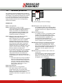
1.2 Water dosing system
After a selection key is pressed, the pump motor is
driven with a controlled time and speed. The pump
rotor displaces a certain amount of cold water from
the cold water reservoir to the bottom of the boiler.
As a result, the hot water in the boiler is pushed
upwards towards a water selector. This selector
uses a rotating movement to select its position
(beverage−dependent). Depending on the selected
beverage, an ingredient is dosed which, together
with the dosed water, is or is not mixed and poured
into a cup.
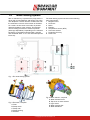
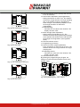
The water dosing system consists of the following
main components:
1. Magnetic valve
2. Float tank
3. Boiler
4. Element
5. Temperature sensor (NTC)
6. Hot water selector
7. Protection float tray
8. Drain hose
Fig. 1 The water dosing system
C
A
B
D
E
F
Fig. 2 Float tank, complete
A. Float
B. Pump motor
C. Pump rotor
D. Pump housing
E. Encoder
A
B
C
D
E
Fig. 3 Water selector, complete
A. Water selector motor
B. Top cover of water selector
C. Light sensor
D. Water rotation disk
E. Water distributor

ECopyright Bravilor Bonamat B.V.
1.3 Start−up
1.3.1 Initialisation
The machine is switched on with the main switch.
On the LCD (Liquid Crystal Display) the following
appear in succession:
Dall symbols that the display can show.
Dthe version number of the software
(microprocessor) loaded from the factory.
Dthe version of the software table (Eeprom), also
loaded from the factory.
This process takes approx. 3 seconds and ends with
the steaming cup in the LCD display to show that
this phase has successfully finished.
1.3.2 Filling
The float tank and the boiler are connected by a
siphon hose. Together, they form a communicating
vessel. When the machine is switched on for the
first time, the float tank will be empty and the float
will be low.
DThe magnetic valve is opened and fills water in
the float tank with a speed of 3,5 litres per minute,
depending on the pressure.
DThe water in the float tank flows to the boiler
through the hose under the float tank.
DAfter the water level has pushed the float
upwards, the water level in the float tank is the
same as that of the boiler. The magnetic valve is
switched off.
DA signal sounds when the level of the float is
reached.
Please note:
Because the float tank is filled faster than the water
”drops” to the boiler, the filling process will be made
with short intervals.
1.3.3 Heating
After the system is completely filled with water,
element is switched on by means of a relay in the
machine.
The lower temperature sensor measures the current
temperature of the water. This ensures that the
water in the boiler is heated to the required final
temperature. The upper temperature sensor
releases the machine for dosing or not. The heating
is switched off when the pre−set temperature has
been reached.
Hot water has a lower specific weight than cold
water. As a result, the hot water in the boiler will not
want to flow back to the float tank through the
siphon hose at the bottom. That part of the system
will therefore remain cold. The latter is very
important because precisely the parts of the float
tank are sensitive for scale.
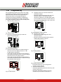
1.3.4 Dosing
Dosing is allowed when:
DThe float is in the top position.
DThe second temperature sensor measures a
temperature higher than the blocking
temperature.
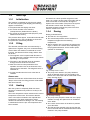
DAfter a selection key is pressed, the pump motor
(fig.4 ) is driven for a certain time, depending on
the programmed amount, with a certain speed
(number of revolutions).
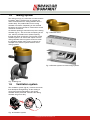
Fig. 4 Pump motor + rotor
DThe pump rotor rotates in the pump chamber,
which is filled with water. This is formed by the
bottom of the float tank and the underneath of the
pump housing (fig.5 ).
Fig. 5 Pump housing
DThe pump rotor pumps the water out of the pump
chamber, through the siphon hose in the bottom
of the boiler.
DAs a result, the hot water in the boiler is pushed
out of the boiler.
DThe float and the magnetic valve ensure that the
level in the float tank is maintained and that water
remains in the pump chamber.

ECopyright Bravilor Bonamat B.V.
The volume of the displaced liquid (yield) is mainly
determined by the time and speed of the pump
motor.
The time that the motor is on is regulated from the
software and is very accurate.
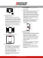
The number of revolutions of the motor is measured
with an active revolution counter.
Figure 6 shows that a disc is mounted on the shaft
of the pump motor (A = Encoder). This disc rotates
at the same speed as the pump rotor.
The encoder rotates between a light sensor (B) and
interrupts a light beam. The interruption of the light
beam is converted to pulses that can be read by the
electronics.
AB
Fig. 6 Encoder
This forms an active revolution regulation that
guarantees that, during the time that the pump
motor is on, the speed and thus the water yield
remain constant.
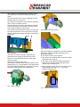
Selection of the dosed hot water:
This machine is fitted with a hot water selector. This
component (fig.7 ) is responsible for the dosed water
from the boiler being dosed in a minimum of 3 and a
maximum of 6 directions (type−dependent).
Fig. 7 Water selector
Fig. 8 Water selector internal
Fig. 9 Water distribution disc
After the machine is switched on, the water selector
goes to the stand−by position according to the
following procedure:
DThe water selector motor is driven.
DThis motor uses a plastic worm to drive the water
distribution disc (fig.8 / 9 ).
DThe cams on the distribution disc interrupt the
light beam of the light sensor and pass these
pulses to the control (fig.10 ).
DWhen the light sensor observes the wide cam on
the distribution disc (fig.10 / 11 ), the initial
position is determined.
Fig. 10 Water distribution disc

ECopyright Bravilor Bonamat B.V.
Fig. 11 Water distribution disc with wide cam
Operation of the water selector after a selection key
is pressed:
DDepending on the selected beverage, the water
selector determines its position.
DAfter the position is determined, the pump motor
is driven.
DThe dosed hot water is pumped into the top of the
water selector (fig.12 A).
DThe water runs through the central hole of the
distribution disc (fig.12 B). It comes out through the
slanted hole at the bottom (fig.12 C).
DAfter this, the water falls into one of the chambers
in the bottom of the water selector (fig.12 D).
DThe water runs to the relevant part through the
hoses that are connected to the water selector.
DThe water selector rotates back to its initial
position.
Please note:
The arrow in fig.12 A shows a small hole on the top
of the water selector cover. This is an aeration hole,
which prevents siphoning. A hose, which goes to the
top of the float tank, is connected to the tulle.
Please note:
Depending on the selected beverage, the water
selector can also rotate during the pumping. This is
done if water has to go to several mixing systems.
ABC
D
Fig. 12 Water selector components

ECopyright Bravilor Bonamat B.V.
1.4 Powder dosing system
The powder dosing system consists of an ingredient
holder (canister) that is driven by a motor (canister
motor).
After the start key is pressed, the canister motor will
rotate after a certain delay. This motor drives a
worm, which transports the ingredient to the canister
outlet.
The control of the canister motor makes it possible
to regulate timing and dosing speed independently.
As a result, the ingredient can be poured into the
mixer at the same time that the water flows out.
However, the canister motor will stop slightly earlier
than the water, to rinse the mixing jug clean.
Depending on the type of ingredient, “beater
springs” are used in the canister. These springs
ensure that less tunnel formation occurs. This is the
caking of ingredient against the walls.

ECopyright Bravilor Bonamat B.V.
1.5 Mixing system
The mixing unit (fig.13 ) mixes the hot water and the
ingredient. After a selection key is pressed, the
water will be dosed in the mixing chamber after a
certain delay. The product falls into the mixing
chamber from above. Depending on the selected
beverage, the mixer will start to rotate with a certain
number of revolutions.
An exhaust opening is mounted on top of the mixing
chamber (fig.14 ). This cover has an opening at the
rear, which is pressed into an exhaust opening
through the sheet−metal work. The function of this
exhaust system is to ensure that vapour from the
mixing chamber does not get the chance to reach
the ingredient holder outlet. Figure 15 shows an
example of an exhaust system suited for three
mixing systems.
Fig. 13 Mixing unit
Fig. 14 Exhaust hood
Fig. 15 Exhaust system for three mixing systems
1.6 Ventilation system
The ventilation system (fig.16 ) removes the steam,
that developes during dosing. So the settling of
warm steam and condensation in the mixing
chamber will be prevented. Therefore the mixing
chamber will get less dirty.
Fig. 16 Ventilation system

ECopyright Bravilor Bonamat B.V.
1.7 Operating system
The operating system consists of a:
DKeyboard
DMain board
1.7.1 Keyboard
The keyboard is located on the front of the machine
and contains various keys and the display. Saved
settings such as the dosing quantities, counters, etc.
are stored here. When this circuit board is replaced,
the customer−specific settings will be lost. A flat
cable connects the keyboard to the main board in
the machine.
1.7.2 Main board
The main board is located on the rear inside the
machine and it is supplied from an external
transformer. This board contains inputs and outputs
of the machine.

ECopyright Bravilor Bonamat B.V.
1.8 Hardware protections
The machine is equipped with a number of hardware
protections. These protections ensure that no
dangerous situations can arise, such as overheating
and/or water in the machine.
1.8.1 Overflow protection
This protection is in the float tank and ensures that,
if the water becomes too high, excess water is
passed through the overflow and hose to the bottom
of the machine.
1.8.2 Back−flow protection
The water from the magnetic valve is sprayed
against the cover of the float tank, via a pipe in the
float tank. Then, it goes into the float tank itself. In
this way, water is prevented from flowing back into
the system and getting into the water system if the
water pressure is released from the magnetic valve.
1.8.3 Boiling protection
The element is controlled by a relay on the main
board. A so−called safety relay has been connected
in series with this relay. If a fault occurs and the
element is still under tension, the safety relay will
interrupt this tension (see the electrical diagram) and
prevent boiling dry.
1.8.4 High temperature safety
switch
The boiling−dry protection is mounted on the outside
of the boiler by means of two Klixons. If the boiler,
for whatever reason, is not switched off by the
control, the Klixons make sure that the voltage on
the element is mechanically switched off to prevent
overheating.
During the boiling dry process, evaporation escapes
from the boiler. This vapour enters the water
selector and can possibly exit between the cover
and distributor. To prevent a few drops from entering
the machine, a drip tray for the water selector has
been made (fig.17 ).
Fig. 17 Drip tray water selector

ECopyright Bravilor Bonamat B.V.
1.9 Software protection
The machine has been equipped with a number of
software protections; the software monitors all inputs
and outputs of the machine throughout the process.
If non−allowed situations arise, the software will
intervene. This intervention results in the machine
being switched off and an error message being
shown on the display.
Fig. 18 LCD display with error message
ERROR LIST
Error 1 Not applicable
Error 2 Temperature in boiler too high:
−If the temperature sensor (NTC) measures a
value that is outside its range (0 Ohm or
infinity), the machine is switched off and
’Error 2’ appears in the LCD display. This
also applies if the boiling protection (see
hardware protection) is activated.
Error 3 Magnetic valve open without selection /
Heating process takes too long:
−When a dosing key is pressed, the magnetic
valve is enabled. If this valve is enabled
without pressing the start key, a timer is
activated. If the magnetic valve is enabled
more than three times within 15 minutes
without the start key being pressed, this
indicates that there is a leakage in the water
system or that the water is boiling. In that
case the machine is switched off.
−At the moment that the float in the protection
water tray has reached the upper position
once, the software enables the protection
relay and all elements are switched off
immediately. In this case the machine will
not be switched off, but show error 3 after 15
minutes.
DReset the machine after having remedied the
fault. This resetting is done by pressing the
reset key on the main board through the hole
in the rear panel using a small screwdriver
(see figure). After this switch off the machine
and on again to make the error code 3
disappear from the screen.
Error 4 Not applicable
Error 5 Water selector in wrong position:
−The water selector returns to its initial
position during start−up and after each
dosing. If the selector cannot find its position
during the execution of this routine, it
switches off and ’Error 5’ appears in the LCD
display.
Error 6 Magnetic valve opened too long:
−If, for whatever reason, the process of filling
the float tank takes too long, the machine is
switched off and ’Error 6’ appears in the LCD
display.
Error 7 Wrong Chip card:
−In a number of cases, it is possible to place
a chip card in a chip card reader. This is
present on the keyboard. Any data present
can be downloaded or uploaded. If the
software on this chip card does not
correspond with the software in the machine,
’Error 7’ appears in the LCD display.
Error 8 Communication error between both prints:
−There is constant communication during
machine start−up and during use. This is
done via the flatcable between the keyboard
and the main board. If communication is
impossible, ’Error 8’ appears in the LCD
display.
Error 9 Pump motor rotates too slow or does not
rotate at all:
−The pump motor is rotating during machine
start−up and during use. The light sensor
detects no or too little pulses and ’Error 9’
will appear in the LCD display.

ECopyright Bravilor Bonamat B.V.
1.10 Programming
The programming is built up by means of a simple
programming carrousel. Have the user instructions
open next to this text. After the programming is
activated by means of the programming key,
settings can be simply activated or changed. By
pressing the programming key again, the settings
are saved the machine returns to the standby mode.
1. Open the door with the key.
Fig. 19 Door open
2. Press the programming key P to start the
programming sequence.
Fig. 20 Programming key
3. Counter contents read−out of all beverages at
the same time. The display shows a 3− and
6−digit number alternately:
−The 3−digit number denotes the total number of
units that were poured since the counter settings
were last reset to zero (day counter).
−The 6−digit number denotes the total number of
units that were poured since the machine was put
into operation (total counter).
Fig. 21 Total counter
3.1 Separate read−out of counter contents of
poured beverages:
−Select the desired beverage with one of the
selection buttons. The relevant counter
contents will appear in the LCD display. After
a few seconds, the counter contents return to
the counter of all beverages at the same time.
Fig. 22 Separate counter contents
3.2 Resetting day counter:
−Select any beverage using one of the
selection buttons.
−Keep the desired selection button pressed
until the day counter is set at 0.
Fig. 23 Day counter
Fig. 24 Day counter to zero
−Press the Enter key to go to the general
selection screen (fig.25 ).
4. General selection screen:
−General programming: press the Enter key and
continue with point 5.
−Beverage−dependent settings: press the
selection key and continue with point 13.

ECopyright Bravilor Bonamat B.V.
Fig. 25 General selection screen
5. Setting the timer (CL):
−The default setting of the timer is OFF, see
fig.26 . Beverages can be pourred at any time.
−When the timer (CL) is set at ON, it is possible
to switch the machine on and off at a maximum of
four various times. Only during these times hot
beverages can be poured from the machine. Only
hot water can be poured at all times! If the
setting is changed to ON, the current time has to
be set, see fig.27 . This time will appear as
default on the display. To set the various times,
go to point 12.
Fig. 26 Default setting of the Timer (CL)
Fig. 27 Set current time
6. Descaling program:
−This machine is fitted with a descaling program.
After the START key is pressed in this state of
the LCD display, the de−scaling program is
started. (For this purpose, read the relevant
section of the user instructions.)
−Press CANCEL within 5 seconds if you decide
not to start the de−scaling program.
7. Preselect the cup/mug/jug setting:
−The machine will return to the set preference
after having distributed the drink or after a
certain time.
8. Boiler temperature:
−Set the temperature of the water in the boiler.
(−5°C − +5°C)
9. Descaling signal:
−Ask your local water company about the hardness
of the water supply. Always select the right
setting. The default setting of the machine is
position 3 (1000L). The machine continuously
registers the time that the inlet valve is open and
therefore the number of litres of water that has
passed through the system. When the number of
registered litres is greater than or equal to the
programmed value, the descaling symbol in the
LCD display starts to flash.
−The positions 6 − 9 are reserved for the use of a
water softening filter preceding the machine.
Always choose the correct setting that
corresponds with the capacity of the water
softening filter.
Fig. 28 Descaling symbol
10. Energy−saving mode:
−Setting the number of minutes/hours, after which
the machine must switch over to the ECO mode.
All functions such as boiler, ventilator and
display illumination switch off and [ECO]
appears in the LCD display. The next time that a
selection key is pressed, the machine switches
on again. Depending on the switch−off time, it
can take a few minutes before the machine is
ready for use again.
11. Copy Card:
−Customer−specific settings can be copied to the
chip card, after which they can be downloaded
to other equivalent machines.
−The procedure can be found on the extranet
under ’Special codes’.
12. Now set the on− and off swichting times. A
maximum of four times can be set in succession,
P1 till P4. Beware of the fact that the times do
not overlap!

ECopyright Bravilor Bonamat B.V.
Fig. 29 First switching on time (P1)
Fig. 30 Set time (ON)
Fig. 31 First switching off time (P1)
Fig. 32 Set time (OFF)
13. General selection screen (all keys that are now
lit can be selected).
14. Amount drink dependent (cup/mug/decanter).
−Setting the amount of water in ml. The software
will convert a larger amount to a longer pumping
time. If the amount of water is changed, the
basic strength is automatically adapted, so that
the strength increases or decreases
proportionally.
14.1 Block dosing:
−Decrease the set value to the minimum. The
display will show ’OFF’.
15. Basic strength (drink dependent):
−Setting amount of ingredient (in %). The
software translates the programmed percentage
to the speed of the canister motor and therefore
the strength of the ingredient. (See ingredient
sheet).
16. General selection screen.
17. Programming (hot water):
18. Amount hot water (cup/mug/decanter).
−Here, the amount of water can be set in ml. The
software will convert a larger amount to a longer
pumping time.
18.1 Blocking amount:
−Decrease the value set to the minimum. The
display will show ’OFF’.
19. General selection screen.
By pressing the programming key P again, the
settings are saved and the machine returns to the
standby mode.
Fig. 33 Programming key / Door closed

ECopyright Bravilor Bonamat B.V.
© 07−2011
-
 1
1
-
 2
2
-
 3
3
-
 4
4
-
 5
5
-
 6
6
-
 7
7
-
 8
8
-
 9
9
-
 10
10
-
 11
11
-
 12
12
-
 13
13
-
 14
14
-
 15
15
-
 16
16
-
 17
17
-
 18
18


BRAVILOR BONAMAT Bolero Turbo Operating Principle
- Category
- Water heaters & boilers
- Type
- Operating Principle
Ask a question and I''ll find the answer in the document
Finding information in a document is now easier with AI
Related papers
-
BRAVILOR BONAMAT B20 HW L/R Operating instructions
-
BRAVILOR BONAMAT RLX4 Owner's manual
-
BRAVILOR BONAMAT B40 W L/R Owner's manual
-
BRAVILOR BONAMAT RLX 41 Owner's manual
-
BRAVILOR BONAMAT RLX 575 Owner's manual
-
-
-
-
-
Other documents
-
 Douwe Egberts Cafitesse 60 Back Office Manual
-
 Douwe Egberts Cafitesse 100 User manual
-
 Douwe Egberts CAFITESSE 014 User manual
-
Animo OptiVend 2 User manual
-
 N&W Global Vending Krea Installation - Use - Maintenance
-
-
Saeco Incanto De Luxe User manual
-
 N&W Global Vending Koro Prime Espresso Installation, Operation & Maintenance Manual
-
-
 EVOCA Manual User manual


