OS Engines OSMG1307 Owner's manual
- Category
- Engine
- Type
- Owner's manual
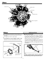
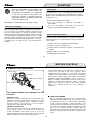
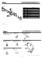
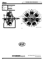
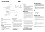
OS Engines OSMG1307 is a seven-cylinder radial overhead-valve four-stroke engine of 70cc displacement. With its finely detailed design and outstanding scale appearance and sound, the engine's quality is second to none. Ideal as a power source for model aircraft, it maintains the same features of stress-free starting, super smooth idling and high torque power which are always the hallmarks of O.S. large size multi-cylinder engines.
OS Engines OSMG1307 is a seven-cylinder radial overhead-valve four-stroke engine of 70cc displacement. With its finely detailed design and outstanding scale appearance and sound, the engine's quality is second to none. Ideal as a power source for model aircraft, it maintains the same features of stress-free starting, super smooth idling and high torque power which are always the hallmarks of O.S. large size multi-cylinder engines.


-
 1
1
-
 2
2
-
 3
3
-
 4
4
-
 5
5
-
 6
6
-
 7
7
-
 8
8
-
 9
9
-
 10
10
-
 11
11
-
 12
12
-
 13
13
-
 14
14
-
 15
15
-
 16
16
-
 17
17
-
 18
18


OS Engines OSMG1307 Owner's manual
- Category
- Engine
- Type
- Owner's manual
OS Engines OSMG1307 is a seven-cylinder radial overhead-valve four-stroke engine of 70cc displacement. With its finely detailed design and outstanding scale appearance and sound, the engine's quality is second to none. Ideal as a power source for model aircraft, it maintains the same features of stress-free starting, super smooth idling and high torque power which are always the hallmarks of O.S. large size multi-cylinder engines.
Ask a question and I''ll find the answer in the document
Finding information in a document is now easier with AI
Related papers
-
OS Engines OSMG0877 Owner's manual
-
-
-
-
-
-
-
O.S. Engines OSMG0898 Owner's manual
-
-
Other documents
-
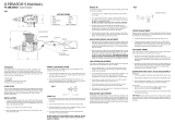
O.S. engine fs-120sIII Owner's Instruction Manual
-
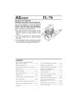 Hobbico FL-70 Owner's manual
-
O.S. engine max-140rx Owner's manual
-
 Bullitt B-217 User manual
-
 Hobbico FL-70 Owner's manual
-
Go Rhino GRT3410 Installation guide
-
 YS 140 LIMITED User manual
-
Generac MAX-12CV HyperMAX-12CV-X Hyper User manual
-
-
 YS FZ63 User manual


