Page is loading ...

Page 1
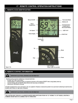
17 - REMOTE CONTROL OPERATION INSTRUCTIONS
B. REMOTE CONTROL INFORMATION
Figure 17A
Remote:
Skytech Premium Transmitter Model AF-4000TSS02 comes standard with the replace.
Touch Screen LCD
Takes four (4) AAA batteries (included)
A. REMOTE ICON IDENTIFICATION
IMPORTANT ELECTRICAL WARNING AND INFORMATION
Electrical wiring must be installed by a licensed electrician.
• Do NOT wire 110V to wall switch.
• Uninterrupted or continuous power is required at all times in IPI systems EXCEPT when using battery back-up.
• Incorrect wiring will override IPI safety lockout and may cause an explosion.
• Disconnect 110V before servicing
A double receptacle box cover and (3) wire nuts are supplied in replace components packet to be used when hardwiring to electrical box
located under rebox on right side of replace.
IMPORTANT ELECTRICAL WARNING AND INFORMATION
THIS SYSTEM GOES THROUGH A CALIBRATION MODE WHEN SWITCHING FROM ‘ON’ TO ‘THERMO’ TO ‘OFF’ MODES, CREATING A
HUMMING SOUND WHICH IS A NORMAL PART OF OPERATION.
SET TEMP Zone
FLAME Zone
FAN Zone
DOWN Button
MODE/SET Button
MODE Zone
ROOM TEMP Zone
TIME/PROG Zone
LIGHT Zone
AUX Zone (not used)
UP Button

Page 2
C. CONTINOUS PILOT - FOR VERY COLD CONDITIONS
The IPI gas control system has the option of a continuous (standing) pilot feature. This allows you to change from a spark-to-pilot system to a stand-
ingpilotsystemduringcoldweatherconditions.Byhavingthepilotoncontinuously,thereboxwillremainwarmandadraftisestablishedinthevent,
allowingthemainburnertoturnonwithlessair-owdisruption.
Whencontinuouspilotmodeisactivated,thepilotwillsparkandlight.WhenreplaceisturnedOFF,thepilotwillremainlitwhenmainburnerhasbeen
turnedOFF.
Thispilotfeaturecanbeactivatedorde-activatedbythehandheldremotecontroltransmitterortheswitchonthemodule.Instructionsonfollowing
page.
D. OPERATION USING BATTERY POWER
E. MATCHING SECURITY CODES
Beforematchingsecuritycodesmakesure120VACisconnectedandpoweredtoreplace,andhandheldremotecontrolisinstalled
with(4)AAAbatteries.ItmaybenecessarytoprogrammaincontrolmoduletoLEARNthesecuritycodeofthehandheldremotecontroluponinitial
use,ifbatteriesarereplaced,orifareplacementremotecontrolispurchasedfromyourdealer.
1. Whenmatchingsecuritycodes,besureslidebuttononmain
controlmoduleisinREMOTE;thecodewillnot“LEARN”ifslide
isinOFF.
2. ProgrammaincontrolmoduletoLEARNanewsecuritycodeby
pushinginLEARNbuttononmaincontrolmoduleusingapencil
pointfor2secondsandletgo(youshouldhearaseriesof‘beeps’
letting you know module is ready to learn a new code).
3. ImmediatelypressMODEbuttononhandheldremotecontrol
(youshouldhearfour‘beeps’inrapidsuccessioninmaincontrol
module,indicatingremotecontrol’scodehasbeenprogrammed
intothemaincontrolmodule).Whenanexistingmaincontrol
module is introduced to a new hand held remote control, the new
security code will overwrite the old one.
Ifiteverbecomesnecessarytoclearthememoryfromthehandheld
remotecontrol,simplypushandholdtheLEARNbuttonfor10seconds
(youshouldhearthreelongbeepsinsuccession).Youmaynowfollow
stepsoutlinedaboveto‘RE-LEARN’securitycodes.
Figure 17E
LEARN BUTTON
PILOT IGNITOR
CONNECTION
PILOT SENSOR
CONNECTION
REMOTE
ON/OFF SWITCH
CONTINUOUS
PILOT SWITCH
120 VAC
ADAPTER
CONNECTION
WIRE HARNESS CONNECTION
TO EXTENSION MODULE
WIRE HARNESS CONNECTION
TO VALVE STEPPER MOTOR
▲
▲
▲
▲
▲
▲
▲
▲
Slide To REMOTE
17 - REMOTE CONTROL OPERATION
IMPORTANT NOTE
When operating replace in this capacity, the only function available is ame modulation.
1. Thisreplacehasanoptionalbatteryoperationifelectricalpowerislost(seePage51,Figure16B).Positionbatterypackwithfour“AA”size
batteriesinstalledbetweenvalveandfrontofreplace.Thisisthecoolestlocationunderrebox,ensuringlongerbatterylife.
2. Nextlocatethereplace'scontrolmodule(seePage51,Figure16A).The"Remote/Off"slideswitchonthebacksideofthemodulemustbeslid
intothe"Off"positiontoallowthebatterypacktofunction.
3. Onceaccomplished,thereplacecanbeturnedfullyonoroffusingtheOn/OffRockerSwitchlocatedonthefrontbracketofthevalveassembly
below.
NOTE: When in Battery Mode, the only functions available are turning the replace on or off.
No ame adjustments are available nor will the remote control be available for the fan, ember lights, thermostat, etc.

Page 3
17 - REMOTE CONTROL OPERATION
F. INTITAL SET-UP
Plug Extension Module and AC Adaptor into receptacles.
Install(4)AAbatteriesintobatterycompartmentofBackup Battery Pack,makingsurebatteriesareinstalledinproperdirection.Positionbetween
valveandfrontofstove.AVelcrostriphasbeenattachedtohelpsecureinplace.
The Hand Held Remoteoperateson(4)AAAbatteries.WerecommendalwaysusingALKALINEbatteriestoextendbatterylifeandimprove
operational performance.
G. GAS TYPE CONVERSION
Press and hold LearnButtononMainControlModulefor20seconds.Abeepwillbeheardlettingyouknowtheprocedurehasbeencompleted.
• If converting from NAT to LP gas: (1) one second long beep
• If converting from LP to Nat gas: (3) three second long beep
Continuewithgastypeconversionbyfollowinginstructionsincludedwithgasconversionkit.
H. CELSIUS/FAHRENHEIT CONVERSION
PressUPandDOWNkeyssimultaneouslytochooseCelsiusorFahrenheit.
I. IMPORTANT SAFETY FEATURE
J. CONTINUOUS PILOT FEATURE
K. CHILDPROOF FEATURE
Thissystemhasamaximumroomtemperaturelimitof90°F(32°C)inbothmanualandthermostatmodes.Whenroomtemperatureisatorabove
this point the system will shut down and the hand held remote control will read OFF. If you turn the system ON when room temperature is still at or
abovethistemperature,thesystemwillagainshutdownafter2minuteswhenroomtemperatureisrecalculated.
ActivationofthisoptionalfeatureisaccomplishedbypressingtheMODE/SET
buttonandARROW UP buttonssimultaneouslyfor5seconds.Thecontinuous
pilot icon will appear on the LCD screen. Pressing both buttons againfor5
seconds will de-activate this feature.
ThisfeaturecanalsobeactivatedviaCONTINUOUS PILOTswitchonMain
ControlModule.
ActivationofthisoptionalfeatureisaccomplishedbypushingMODE/SET
buttonandARROW DOWN buttonssimultaneouslyfor5seconds.The
childproof iconwillappearontheLCSscreen.Whenatransmitterbutton
ispressedtheiconwillashonscreen,butnosignalwillbetransmitted.
Pressingandholdingthesesametwobuttonsagainformorethan5
seconds will de-activate this function.
This feature controls only manual functions of the hand held remote,
automaticfunctions(thermostatmode)willnotbeaffected
.
Figure 17J
Figure 17K

Page 4
17 - REMOTE RECEIVER INFORMATION
L. MANUAL MODE
M. FAN MODE
N. LIGHTING MODE
Thisremotecanbemanuallyorthermostaticallyoperated.
Press MODE/SETbuttonformanualON.Theameiconwillappearon
the LCD screen. Press MODE/SETbuttonagaintoputthecontrolinto
THERMO mode. Pressing MODE/SETagainwillturnreplaceOFF.
Thisremotewilloperatethefan,allowingfor(6)differentspeedlevels.
Press the MODE/SETbutton.TheFANicon(*)willlightup.Pressthe
FAN icon on the LCD screen, then the UP or DOWN ARROWS to select
thedesiredfanspeedlevel.PresstheMODE/SETbuttontosetorwait
15secondsandthecontrolwillautomaticallyacceptthenewsetting,exit
function setting mode and LCD display will return to normal view.
Thisremotewilloperatethelights,allowingfor(6)differentlightlevels.
When LIGHTbuttonispressed,PresstheMODE/SETbutton.TheLIGHT
iconwillappearontheLCDscreen.PresstheLIGHT icon on the screen.
Press UP or DOWNbuttonstoselectdesiredlightlevel.PresstheMODE/
Setbuttonorwait15secondsandthecontrolwillautomaticallyacceptthe
newsetting,exitfunctionsettingmodeandLCD display will return to normal
view.
Figure 17L
Figure 17N
Figure 17M
IMPORTANT NOTE
Delayed ON/OFF - The fan will not turn on until replace has been
burning for 5 minutes and will not turn off for 12 minutes after
replace has been turned off.
EXCEPTION: If replace is turned back on during 12 minute off-
delay time frame, the fan will remain on. This applies to MANUAL and
THERMO modes
.
IMPORTANT NOTE
The MODE/SET button operates in a series that will cycle from ON to
THERMO to OFF.
NOTE
The replace does not have to be burning to operate the lights.

Page5
O. FLAME MODE
Thisremotewilloperatetheame,allowingfor(6)differentameheight
levels.PresstheMODE/SETbutton.TheFLAMEiconwillappearonthe
LCDscreen.PresstheFLAMEicononthenscreen,thenressUP or DOWN
buttonstoselectdesiredamelevel.PresstheMODE/SETbuttontosetor
wait15secondsandthecontrolwillautomaticallyacceptthenewsetting,
exitfunctionsettingmodeandLCD display will return to normal view.
P. THERMO (THERMOSTATE) MODE
Thisremotefeatureallowsyoutothermostaticallycontrolthereplacewhenhandheld
remote is set to THERMO mode.
SetTemperatureRange:45˚F(7˚C)to90˚F(32˚C).
SetremotetoTHERMO modebypressingMODE/SETbuttontwice."ON THERMO"
willappearontheLCDscreen.TouchtheSETTEMPZONEonthescreen,thenpress
theUPorDOWNARROWbuttonstothedesiredtemperature.Within5secondsreplace
will operate to that set temperature.
Set temperature will only appear when THERMOSTAT MODE is activated, but is
implemented in all MODES with the exception of MANUAL MODE.
To exit THERMO mode, press the MODE/SET button. This also shuts the replace
OFF.
IMPORTANT NOTE
When in THERMO mode the replace will not turn on until room temperature falls below SET TEMPERATURE.
IMPORTANT NOTE
The replace will initially light at the highest level. After 5 seconds the ame will adjust to last chosen level before replace was turned
OFF. This applies to MANUAL and THERMO modes
.
IMPORTANT NOTE
The ame height can adjust up to (6) different height levels according to amount of heat required. This range however is dictated by the
Flame Level setting (see previous page). When desired temperature is met, the replace will shut off until more heat is required.
Figure 17O
Figure 17P
17 - REMOTE RECEIVER INFORMATION

Page6
R. SYSTEM OPERATION WITHOUT HANDHELD REMOTE
Thissystemisdesignedtooperatewiththehandheldremoteorathermostat,butintheunlikelyeventthatitisrequiredtobeoperatedwithoutthe
hand held remote or a thermostat, follow this simple procedure.
SlideREMOTE /OFF switch on main control module to OFF.ThereplacecannowbelitandshutoffbyuseoftheON/OFF rocker switch located
nexttothemodule.
LEARN BUTTON
PILOT IGNITOR
CONNECTION
PILOT SENSOR
CONNECTION
REMOTE
ON/OFF SWITCH
CONTINUOUS
PILOT SWITCH
120 VAC
ADAPTER
CONNECTION
WIRE HARNESS CONNECTION
TO EXTENSION MODULE
WIRE HARNESS CONNECTION
TO VALVE STEPPER MOTOR
▲
▲
▲
▲
▲
▲
▲
▲
Switch
Remote
To OFF
Figure 17R
IMPORTANT NOTE
When operating replace in this capacity, the only function available is burner operation on HI.
17 - REMOTE RECEIVER INFORMATION
Q. SET THE DAY AND TIME DISPLAY
Thecurrentdayoftheweekandtimeofdaywillbecontinuouslydisplayedinthe
TIME/PROGZone(exceptduringSETUPoperations).
Thedayoftheweekwillbedisplayedasoneofthefollowing:S,M,T,W,T,F,S.
TheTimeofdaywillbein12-hourAM,12-hourPMformatwithmidnightbeing
displayedas12:00am.
DAY-PressandholdtheMODEZoneortheMODE/SETbuttonfor5seconds.
PresstheUPorDOWNbuttonstoadjusttothedesireddayoftheweek.
PresstheMODE/SETbuttontosetorwait15secondsandthecontrolwill
automaticallyaccepttheday,thenenterthehourofdayadjustment.
HOUR:PresstheUPorDOWNbuttonstoadjustthehouroftheday.The
timewilladvancein1-hourincrements;AMandPMwillchangewhenthehour
advancesto12:00midnightand12:00noonrespectively.Oncethedesiredtime
ofdayisdisplayed,presstheMODE/SETbuttontosetorwaitfor15seconds
and the control will automatically accept the hour, then enter minute of hour
adjustment.
MINUTE(S):PresstheUPorDOWNbuttonstoadjusttheminuteofthehour.
Thetimewilladvancein1-minuteincrements.PresstheMODE/SETbutton
oncethedesiredminuteisreachedorwait15secondsandthecontrolwill
automaticallyacceptthenewtime,andexitDAY/TIMESetupandreturnto
normal screen operation.
Figure 17Q
/