Page is loading ...

1
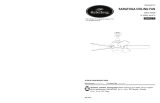
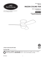
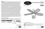
PARKLAKE CEILING FAN
ITEM #0747605
MODEL #00878
Español p. 16
Serial Number
Purchase Date
Harbor Breeze ® is a registered trademark of LF,
LLC. All Rights Reserved.
Questions, problems, missing parts? Before returning to your retailer, call our customer
service department at 1-800-643-0067, 8 a.m. - 6 p.m., EST, Monday - Thursday
8 a.m. - 5 p.m., EST Friday.
EB15472
ATTACH YOUR RECEIPT HERE
UL #52-CHF
Lowes.com/harborbreeze Lowes.com/harborbreeze
COVER - Page 1
Page 12

3
2
TABLE OF CONTENTS
Safety Information ................................................................................................................2
Package Contents ................................................................................................................4
Hardware Contents...............................................................................................................5
Preparation ...........................................................................................................................5
Assembly Instructions...........................................................................................................6
Operating Instructions ........................................................................................................12
Care and Maintenance .......................................................................................................13
Troubleshooting ..................................................................................................................14
Warranty .............................................................................................................................15
Replacement Parts List ......................................................................................................15
SAFETY INFORMATION
SAFETY INFORMATION
WARNING
CAUTION
READ AND SAVE THESE INSTRUCTIONS
Please read and understand this entire manual before attempting to assemble, operate or install the
product.
• When using an existing outlet box, be sure the box is securely attached to the building structure
and can support the full weight of the fan, so to avoid potential serious injury or death.
• All wiring must be in accordance with the National Electrical Code “ANSI/NFPA 70” and local
electricalcodes.Electricalinstallationshouldbeperformedbyaqualiedlicensedelectrician.
• DONOTusebulbswithwattagegreaterthanthemaximumvaluestatedonthextureandin
thismanual.Usingahigherwattagebulbthanspeciedwillincreasexturetemperatureand
causeriskofre.
• Disconnect the electrical supply circuit to the fan before installing kit.
• Electrical diagrams are for reference only.
• The net weight of this fan including the light kit is: 22.93 lbs.
• ELECTRIC SHOCK HAZARD - Do not install this fan with variable speed wall control or
wall-mounted dimmer switch. It will permanently damage the fan’s remote control receiver
and cause the fan’s functions to fail.
• ELECTRIC SHOCK HAZARD - To reduce the risk of electric shock, do not use this fan with any
solid-state speed control device.
• ELECTRIC SHOCK HAZARD - To reduce the risk of electric shock, make sure the electricity
has been turned off at the circuit breaker or fuse box before beginning installation.
• PERSONAL INJURY HAZARD - To reduce the risk of injury to persons, install fan so the
bladesare7ft.(2.1m)abovetheoor.
ON
ON / OFF switch NO Variable speed wall control NO Dimmer switch
• FIRE,ELECTRICSHOCKORPERSONALINJURYHAZARD-Toreducetheriskofre,
electric shock, or personal injury, mount to an outlet box marked “ACCEPTABLE FOR FAN
SUPPORT OF 35.1 lbs OR LESS” and use the mounting screws provided with the outlet box.
Mostoutletboxescommonlyusedforthesupportoflightingxturesarenotacceptableforfan
supportandmayneedtobereplaced.Consultaqualiedlicensedelectricianifindoubt.
• PERSONAL INJURY HAZARD - To reduce the risk of personal injury, do not bend the blade
brackets when installing the brackets, balancing the blades, or cleaning the fan. DO NOT insert
foreign objects in between the rotating fan blades.
This equipment has been tested and found to comply with the limits for a Class B digital device,
pursuant to Part 15 of the FCC Rules. These limits are designed to provide reasonable protection
against harmful interference in a residential installation. This equipment generates, uses and can
radiate radio frequency energy and, if not installed and used in accordance with the instructions,
may cause harmful interference to radio communications. However, there is no guarantee
that interference will not occur in a particular installation. If this equipment does cause harmful
interference to radio or television reception, which can be determined by turning the equipment off
and on, the user is encouraged to try to correct the interference by one or more of the following
measures:
• Reorient or relocate the receiving antenna.
• Increase the separation between the equipment and receiver.
• Connect the equipment into an outlet on a circuit different from that to which the receiver is
connected.
• Consult the dealer or an experienced radio/TV technician for help.
CAUTION:Anychangesormodicationsnotexpresslyapprovedbythegranteeofthisdevicecould
void the user’s authority to operate the equipment.
This device complies with Part 15 of the FCC Rules. Operation is subject to the following two
conditions:
(1) This device may not cause harmful interference, and (2) this device must accept any
interference received, including interference that may cause undesired operation.
Lowes.com/harborbreeze Lowes.com/harborbreeze
Page 3
Page 2

54
HARDWARE CONTENTS (shown actual size)
PREPARATION
Before beginning assembly of product, make sure all parts are present. Compare parts with package
contents list and hardware contents list. If any part is missing or damaged, do not attempt to
assemble the product.
Estimated Assembly Time: 45 minutes
Tools Required for Assembly (not included): Phillips screwdriver, step ladder, electrical tape, pliers,
wire cutters, wire strippers.
Helpful Tools (not included): Electrical Circuit tester
PACKAGE CONTENTS
PART DESCRIPTION QUANTITY
A Mounting Bracket 1
B Canopy 1
C Canopy Cover 1
D Yoke Cover 1
E Downrod 1
F Motor Assembly 1
G Fitter Plate 1
PART DESCRIPTION QUANTITY
H Blade 5
I Light Fitter Assembly 1
J Shade 1
K Bulb 4
L Remote Pack 1
A
B
C
D
E
F
G
K
I
J
L
H
Blade Screw
Qty. 16
Wire Connector
Qty. 9
Lowes.com/harborbreeze Lowes.com/harborbreeze
Page 4 Page 5

6 7
ASSEMBLY INSTRUCTIONS ASSEMBLY INSTRUCTIONS
1. Determine mounting method to use.
A - Downrod Mount
B - Angle Mount
Important: If using the angle mount, check to
makesuretheceilingangleisnotsteeperthan20˚
4. Remove the preassembled pin and clip from
downrod (E). Insert downrod (E) through canopy
(B) and yoke cover (D). Thread wires from fan
motor assembly (F) through downrod (E).
2. Remove the mounting bracket (A) from the canopy
(B) by loosening the four screws on the top of the
canopy (B). Remove the two non-slotted screws and
save.
3. Install mounting bracket (A) to outlet box (not
included) by sliding mounting bracket (A)
over the two outlet box screws (not included).
Securely tighten two outlet box screws.
IMPORTANT: If angle mounting, make sure
open end of mounting bracket (A) is installed
facing the ceiling.
5. Loosen the two set screws from the yoke. Slip
downrod (E) into the yoke, then re-insert pin
and clip. Tighten set screws to secure.
E
B
D
Clip
Pin
4
Loosen but
do not remove
Remove
and save
A
B
2
1
Pin
Yoke
Clip
Set screw
E
F
5
3 6
Outlet box
A
6. Carefully lift the motor assembly (F) up to the
mounting bracket (A). Install hanger ball on the
top of downrod (E) into opening of mounting
bracket (A). Rotate fan until slot on hanger ball
engages the tab on the mounting bracket (A).
DANGER: Be careful when aligning the tab to
the slot! If not fully engaged, there is a possibility
of fan falling, which may result in serious injury
or death.
Lowes.com/harborbreeze Lowes.com/harborbreeze
Page 6 Page 7
Tab
Slot
A
E

8 9
ASSEMBLY INSTRUCTIONS ASSEMBLY INSTRUCTIONS
Hardware Used
10. Insert blade (H) through the slot in the motor
assembly (F), aligning the three screw holes in
the blade (H) with the screw holes in the motor
assembly (F). Secure blade (H) using blade
screws (AA).
8. Twist wire ends together and screw wire connectors
(BB) on in a clockwise direction. Tape wire connectors
(BB) and wires together with electrical tape (not
included).
11. Remove one of the three screws from the
support plate preassembled underneath the
motor assembly (F). Loosen but do not remove
the other two screws.
9. Slide the canopy (B) up to the ceiling and over
the two screws on the mounting bracket (A).
Rotate the canopy (B) to lock it in place, then
secure with previously loosened/removed
screws.
12. Pass the BLUE and WHITE wires from the
motor assembly (F) through the center hole
ofthetterplate(G).Alignthetwokeyslotsin
thetterplate(G)withthetwoscrewsinthe
support plate below the motor assembly (F).
Placethetterplate(G)overthetwoloosened
screwsandturnthetterplate(G)clockwise
until it locks. Re-install the previously removed
screw, then tighten all screws securely.
7. Insert receiver from the remote pack (L) into mounting
bracket(A)withtheatsidetowardtheceiling.
Connect the GREEN/GROUND wire from fan to the
BARE/GROUNDED supply wire. Connect the BLACK
wire (AC IN L) from the receiver to the supply BLACK
wire. Connect the BLACK wire (TO MOTOR L) from
the receiver to the BLACK wire from fan. Connect
the WHITE wire (AC IN N) from receiver to the supply
WHITE wire. Connect the WHITE wire (TO MOTOR
N) from the receiver to the WHITE wire from fan.
Connect the BLUE wire (FOR LIGHT) from receiver
to the BLUE wire from fan.
WARNING: Be sure no bare wire or wire strands are
visible after making connection. Place GREEN and
WHITE connections on opposite side of box from
the BLACK and BLUE (if applicable) connections.
The splices should be turned upward and pushed
carefully up into the outlet box.
L
Black
White
Ground/Green
Ground/Green
White
White
Blue
Black
Black
F
A
7
H
H
AA
F
10
8 11
B
Screw
Outlet box
9 12
x 6
Wire Connector
BB
BB
Screw
Support plate
Screw
G
F
Repeat for the remaining blade assemblies.
Hardware Used
AA
Blade Screw
x 16
Lowes.com/harborbreeze Lowes.com/harborbreeze
Page 8 Page 9

10
ASSEMBLY INSTRUCTIONS
13. Removeoneofthethreescrewsfromthetter
plate (G). Loosen but do not remove the other
two screws.
14. Connect the BLUE wire from the fan motor
assembly (F) to the BLACKwirefromthelighttter
assembly (I) and connect the WHITE wire from the
fan motor assembly (F) to the WHITE wire from the
lighttterassembly(I)byconnectingtheplugs.
F
G
Screw 2
13
14
Page 10 Page 11
11
15
G
F
I
White
Blue
Black
15. Alignthetwokeyslotsinthelighttterassembly(I)
withthetwoloosenedscrewsonthetterplate(G).
Placethelighttterassembly(I)overthetwoscrews
andturnthelighttterassembly(I)clockwiseuntilit
locks. Re-install the previously removed screw, then
tighten all screws securely.
Screw 2
I
ASSEMBLY INSTRUCTIONS
16. Installbulbs(K)tosocketsonlighttterassembly(I).
IMPORTANT NOTE: Your fan has an energy-saving
wattage limiter included. If you replace the bulbs with
more than 190 watts, your fan will automatically turn
off. Ensure bulb wattage is always less than 190 watts!
K
I
16
Screw
G
17
J
J
G
Screw
18
17. Removethreescrewsfromthesideoftter
plate (G) and save.
18. Hang the shade (J) by aligning the hook on
theshade(J)withtheholeonthetterplate
(G). Carefully push up the shade (J), aligning
thescrewholesintterplate(G)withshade
(J). Re-install the three screws and tighten
securely.
Lowes.com/harborbreeze Lowes.com/harborbreeze

For the DIMMER function, press and hold the button. Light will dim. Release the button when light
is at desired level.
Note: This remote control has a memory function. The receiver stores the fan speed and light setting
when the fan is turned off. When fan is turned on again, it starts with the most recent settings.
12
13
OPERATING INSTRUCTIONS
(2) Fan Control / Dimmer:
0 Low speed
0 0 Medium speed
0 0 0 High speed
O Turns fan off
Turns light on or off
2. REVERSE SWITCH:
When the season changes, you may want to change the
direction the fan blades spin. To switch between clockwise
andcounterclockwiserotation,ipthefanreversalswitch.
WARNING: Wait for fan to stop before reversing switch.
• In warmer weather, counterclockwise rotation creates a
downwardairow,whichcoolstheair.Pushtheswitch
LEFT and see a Sun icon.
• In cooler weather, clockwise rotation creates an upward
airow,whichmoveshotairfromtheceilingintotheroom.
PushtheswitchRIGHTandseeaSnowakeicon.
1. REMOTE CONTROL:
(1) Install Battery/Learning Process:
Remove the battery cover from the back of the remote
found in the remote pack (L). Insert the battery from the
remote pack (L) into the remote; ensure polarity of battery
matches the polarity indicated in the battery compartment
-- positive (+) to positive (+) and negative (-) to negative (-).
Replace the battery cover.
If you need to change the dip switches in the remote control
due to a potential interference issue, slide the dip switches
to your choice of either up or down -- the factory setting is
up. Within 30 seconds of turning the fan’s power on, press
and hold the “Learn” button on the remote control for 1
second. Once the receiver has detected the set frequency,
the light of the fan will blink twice. Replace the battery
cover.Toconrmtheremotecontrolandreceiverhave
paired successfully press any of the fan speed control
buttons on the remote control.
L
L
Learn key
Dip switch
Sun icon
Snowflake icon
1
CARE AND MAINTENANCE
• IMPORTANT: Shut off main power supply before beginning any maintenance.
• DO NOT use water or a damp cloth to clean the ceiling fan.
• At least twice each year, tighten all screws and lower the canopy to check mounting bracket
screws and downrod assembly.
• Cleanfanhousingwithonlyasoftbristlebrushorlint-freeclothtoavoidscratchingthenish.
Clean blades with a lint-free cloth. You may occasionally apply a light coat of furniture polish
to wood blades for added protection.
• Bulb replacement: Use 40-watt max. candelabra-base E12-type incandescent bulbs; CFLs and
LEDs are not recommended for this item.
• Battery replacement: Use an A23 12-volt alkaline battery for the remote control.
Note: If you have more than one remote controlled fan installed in
the same location, you may want to change the frequency of the
remote control to avoid any possible interference between remote
controls. To change the frequency of the remote control, change
the dip switch settings as described below:
OPTIONAL: If desired, the wall bracket in remote pack (L)
can be installed to house the remote control. Remove the
small plate preassembled on the wall bracket and use the
screws in remote pack (L) to secure the wall bracket at
desired mounting location. Replace the small plate, then
rest the remote control into wall bracket.
Small plate
Wall bracket
Screws
Lowes.com/harborbreeze Lowes.com/harborbreeze

Printed in China
14 15
PART DESCRIPTION PART #
E Downrod 102200-0176BN
H Blade 108003-3047K6
I Light Fitter Assembly 105000-0739BN
J Shade 991300-061200
L Remote Pack 990700-009300
WARRANTY
REPLACEMENT PARTS LIST
For replacement parts, call our customer service department at 1-800-643-0067, 8 a.m. - 6 p.m.,
EST, Monday - Thursday, 8 a.m. - 5 p.m., EST, Friday.
The manufacturer warrants this fan to be free from defects in workmanship and material present at
time of shipment from the factory for lifetime limited from the date of purchase. This warranty applies
only to the original purchaser. The manufacturer agrees to correct such defect at no charge or at our
option replace the ceiling fan with a comparable or superior model.
To obtain warranty service, present a copy of your sales receipt as proof of purchase. All cost of
removal and reinstallation are the expressed responsibility of the purchaser. Any damage to the
ceilingfanbyaccident,misuse,orimproperinstallation,orbyafxingaccessoriesnotproducesby
the manufacturer of the fan, are at the purchaser’s own responsibility. The manufacturer assumes
no responsibility whatsoever for fan installation during the lifetime limited warranty. Any service
performed by an unauthorized person will render the warranty invalid.
Duetovaryingclimaticconditions,thiswarrantydoesnotcoverchangesinbrassnish,rusting,
pitting,tarnishing,corroding,orpeeling.Brassnishfansmaintainthebeautywhenprotectedfrom
varying weather conditions. Any glass provided with this fan is not covered by this warranty. Any
replacementofdefectivepartsfortheceilingfanmustbereportedwithintherstyearfromthedate
of purchase. For the balance of the warranty, call our customer service department at 1-800-643-
0067 for return authorization and shipping instructions so that we may repair or replace the ceiling
fan. Any fan or parts returned improperly packaged is the sole responsibility of the purchaser. There
is no further expressed warranty. The manufacturer disclaims any and all implied warranties.
The duration of any implied warranty which can not be disclaimed is limited to the lifetime limited
periodasspeciedinourwarranty.Themanufacturershallnotbeliableforincidental,consequential
or special damages arising at or in connection with product use or performance except as may
otherwisebeaccordedbylaw.Thiswarrantygivesyouspeciclegalrightsanyoualsohaveother
rights which may vary from state to state. This warranty supersedes all prior warranties.
Note: A small amount of “wobble” is normal and should not be considered a defect.
E
I
J
L
H
TROUBLESHOOTING
PROBLEM POSSIBLE CAUSE CORRECTIVE ACTION
Fan does not move. 1. Fan reversal switch not engaged.
2. Battery is old or expired.
3. Power is off or fuse is blown.
4. Faulty wire connection.
1. Pushswitchrmlyeitherway.
2. Use a new battery.
3. Turn power on or check fuse.
4. Turn power off. Loosen canopy,
check all connections.
Noisy operation. 1. Blades are loose.
2. Cracked blade.
3. Non-approved speed control.
1. Tighten all blade screws.
2. Replace blades (call customer
service).
3. Replace with an approved speed
control device.
Excessive wobbling. 1. Unbalanced blades.
2. Blades are loose.
3. Blade arms incorrectly attached.
4. Fan not securely mounted.
5. Fan too close to vaulted ceiling.
1. Use blade balancing kit (sold
seperately)
2. Tighten all blade screws.
3. Re-install blade arms.
4. Turn power off. Carefully loosen
canopy, remount securely.
5. Lower or move fan. Extension
downrods may be ordered (call
customer service).
Remote control
malfunction.
1. NoashontransmitterLED.
2. The remote control does not work.
1. Check if the battery is installed
into the remote control. Make
sure the battery is installed
properly. One side of the battery
is positive and the other is
negative.
2. Sync the remote control to
thereceiver following the steps
described in step 1 on page 12.
Make sure power to the fan is
off before beginning the sync
process.
Lowes.com/harborbreeze Lowes.com/harborbreeze
Page 11
Harbor Breeze ® is a registered
trademark of LF, LLC. All Rights
Reserved.
/