Page is loading ...

Manual 2100-468E
Page 1 of 27
SINGLE PACKAGE
HEAT PUMPS
INSTALLATION INSTRUCTIONS
© Copyright 2006
Manual : 2100-468E
Supersedes: 2100-468D
File: Volume II Tab 11
Date: 05-28-09
Bard Manufacturing Company, Inc.
Bryan, Ohio 43506
Since 1914 . . . Moving ahead, just as planned.
MODELS
PH13242-A PH13302-A
PH13362-A PH13362-B
PH13422-A PH13422-B
PH13422-C PH13482-A
PH13482-B PH13482-C
PH13602-A PH13602-B
PH13602-C

Manual 2100-468E
Page 2 of 27
CONTENTS
Getting Other Informations and Publications
General Instructions
Important ................................................................ 3
Shipping Damage .................................................... 4
General ................................................................ 4
Field-Installed Heater Packages (Optional) ............. 4
Installation
Location ................................................................ 9
Slab Mounting .......................................................... 9
Winter Installation .................................................... 9
Typical Installations ......................................... 9 & 12
Condensate Drain Trap ......................................... 12
Air Filters .............................................................. 12
Thermostats ........................................................... 13
Wiring – Main Power ............................................. 14
Wiring – 24V Low Voltage Control Circuit ............. 14
Thermostat Indicator Lamps .................................. 15
Emergency Heat Position ...................................... 15
Transformer Taps ................................................... 15
Compressor Cutoff Thermostat and Outdoor
Figures
Figure 1 Unit Dimensional Drawing ....................... 8
Figure 2 Slab Mounting at Ground Level ............ 10
Figure 3 Airflow and Service Access
Clearances ............................................ 10
Figure 4 Elevated Mounting Platform ................... 11
Figure 5 Condensate Drain Trap ......................... 12
Figure 6 Low Voltage Wiring ............................... 14
Figure 7 Unit 24V Terminal Board (5–10 KW) ..... 15
Figure 8 Unit 24V Terminal Board (15–20 KW) ... 16
Figure 9 Heat Pump Control Board ..................... 19
Figure 10 Fan Blade Setting ................................. 22
Figure 11 Brazing Diagram ................................... 25
Figure 12 Motor Connections ................................ 26
Figure 13 Wiring (Connections/Voltage) ............... 27
Start Up and Operation
General .............................................................. 17
Topping Off System Charge................................... 17
Safety Practices ..................................................... 17
Start Up Notes ....................................................... 17
Three Phase Scroll Compressor Start Up
Information ............................................................. 18
Sequence of Operation .......................................... 18
Defrost Cycle ......................................................... 19
Troubleshooting
Solid State Heat Pump Control
Troubleshooting Procedure ................................... 20
Troubleshooting Guide .......................................... 20
Checking Temperature Sensor Check Out ............ 21
Temperature vs. Resistance of
Temperature Sensor Chart .................................... 21
Service
Service Hints ......................................................... 22
Pressure Service Ports .......................................... 22
Refrigerant Charge ................................................ 22
Fan Blade Settings ................................................ 22
Suction and Discharge Tube Brazing .................... 25
Pressure Tables ............................................. 23 & 24
Troubleshooting GE ECM Blower Motors . 26 & 27
Tables
Table 1 Rated CFM and ESP .............................. 4
Table 2 Electrical Data ......................................... 5
Table 3 Optional Field Installed Heater
Packages ................................................ 6
Table 4 Opt. Field Installed Elec. Heater ............. 7
Table 5 Required Filters..................................... 12
Table 6 Heat Pump Thermostats ....................... 13
Table 7 Thermostat Wire Size ........................... 13
Table 8 Compressor Cutoff Thermostat
Wiring (5 - 10 KW) ............................... 16
Table 9 Compressor Cutoff Thermostat
Wiring (15 - 20 KW) ............................. 16
Table 10 Fan Blade Setting Dimensions.............. 22
Table 11 Pressure Table - Cooling ....................... 23
Table 12 Pressure Table - Heating ...................... 24
Table 13 Indoor Blower Performance .................. 25

Manual 2100-468E
Page 3 of 27
Getting Other Information and Publications
These publications can help you install the air conditioner
or heat pump. You can usually find these at your local
library or purchase them directly from the publisher. Be
sure to consult current edition of each standard.
National Electrical Code ........................... ANSI/NFPA 70
Standard for the Installation ................... ANSI/NFPA 90A
of Air Conditioning and Ventilating Systems
Standard for Warm Air .......................... ANSI/NFPA 90B
Heating and Air Conditioning Systems
Load Calculation for ................................ ACCA Manual J
Residential Winter and Summer Air Conditioning
Duct Design for Residential ................... ACCA Manual D
Winter and Summer Air Conditioning and Equipment
Selection
FOR MORE INFORMATION, CONTACT
THESE PUBLISHERS:
ACCA Air Conditioning Contractors of America
1712 New Hampshire Ave. N.W.
Washington, DC 20009
Telephone: (202) 483-9370
Fax: (202) 234-4721
ANSI American National Standards Institute
11 West Street, 13th Floor
New York, NY 10036
Telephone: (212) 642-4900
Fax: (212) 302-1286
ASHRAE American Society of Heating Refrigerating,
and Air Conditioning Engineers, Inc.
1791 Tullie Circle, N.E.
Atlanta, GA 30329-2305
Telephone: (404) 636-8400
Fax: (404) 321-5478
NFPA National Fire Protection Association
Batterymarch Park
P.O. Box 9101
Quincy, MA 02269-9901
Telephone: (800) 344-3555
Fax: (617) 984-7057

Manual 2100-468E
Page 4 of 27
GENERAL INSTRUCTIONS
IMPORTANT
The equipment covered in this manual is to be installed by
trained, experienced service and installation technicians.
Any heat pump is more critical of proper operating charge
and an adequate duct system than a straight air conditioning
unit. All duct work, supply and return ducts, must be
properly sized for the design airflow requirement of the
equipment. ACCA is an excellent guide to proper sizing.
All duct work or portions thereof not in the conditioned
space should be properly insulated in order to both
conserve energy and prevent condensation or moisture
damage.
SHIPPING DAMAGE
Upon receipt of equipment, the carton should be checked
for external signs of shipping damage. If damage is found,
the receiving party must contact the last carrier
immediately, preferably in writing, requesting inspection
by the carrier’s agent.
GENERAL
The refrigerant system is completely assembled and
charged. All internal wiring is complete.
The unit is designed for use with or without duct work.
Flanges are provided for attaching the supply and return
ducts.
These instructions explain the recommended method to
install the air cooled self-contained unit and the electrical
wiring connections to the unit.
These instructions and any instructions packaged with any
separate equipment required to make up the entire heat
pump system should be carefully read before beginning the
installation. Note particularly “Starting Procedure” and any
tags and/or labels attached to the equipment.
While these instructions are intended as a general
recommended guide, they do not supersede any national
and/or local codes in any way. Authorities having
jurisdiction should be consulted before the installation is
made.
FIELD INSTALLED HEATER PACKAGES
(OPTIONAL)
These packaged heat pumps are manufactured without
supplementary electric heaters. Supplementary heaters are
available for simple, fast field installation.
A separate power circuit is required for the supplementary
heaters.
IMPORTANT: Refer to Table 1 when designing duct work
for maximum available static pressure with heater installed.
Refer to Tables 2 and 4 for proper application information
on all available heater combinations and what units they
can be used with. It also shows the applicable circuit
ampacities, fuse size, and wire size for each heater
combination.
TABLE 1
RATED CFM AND EXTERNAL STATIC PRESSURE (ESP)
NOTE: Motor will adjust to deliver rated airflow.
ledoM
detaR
MFC
dednemmoceR
egnaRwolfriA
detaR
PSE
mumixaM
PSE
4231HP008
etoN
01.005.0
0331HP0001
etoN
51.005.0
6331HP0011
etoN
51.005.0
2431HP0041
etoN
51.005.0
8431HP0551
etoN
02.005.0
0631HP0571
etoN
02.005.0

Manual 2100-468E
Page 5 of 27
* 75 degree C copper wire
** Maximum time delay fuse of HACR type circuit breaker
TABLE 2
ELECTRICAL DATA
ledoMA-24231HPA-20331HPA-26331HPB-26331HPA-22431HPB-22431HPC-22431HPA-28431HPB-28431HPC-28431HPA-20631HPB-20631HPC-20631HP
gnitaRcirtcelE
AtkC-zH06
1-06-802/0321-06-802/0321-06-802/0323-06-802/0321-06-802/0323-06-802/0323-06-0641-06-802/0323-06-802/0323-06-0641-06-802/0323-06-802/0323-06-064
egnaRegatoVgnitarepO352-791352-791352-791352-781352-791352-781605-414352-791352-781605-414352-791352-781605-414
yticapmAtiucriCmuminiM02227281335221639241936271
CSCB31415.711112518
22418
62619
*eziSeriWdleiF210101210101418012180101
eziSeriWdnuorG21018210101418014180121
**.xaM-esuFyaleD03030452055351050402060452
802-302-spmAtinUlatoT2.21/2.113.61/8.419.12/4.914.51/9.319.22/9.129.71/1.714.016.62/7.422.91/0.817.019.82/3.529.91/7.719.11
AtiucriC-rosserpmoC
epyTrosserpmoCllorcSllorcSllorcSllorcSllorcSllorcSllorcSllorcSllorcSllorcSllorcSllorcSllorcS
stloV802/032802/032802/032802/032802/032802/032064802/032802/032064802/032802/032064
spmAdaoLdetaR9/85.21/115.71/5111/5.91.71/1.610.21/3.117.76.02/7.812.31/0.217.79.22/3.919.31/7.116.8
spmArotoRkcoL3.85/3.8537/3797/9788/88511/511511/51105711/7111.38/1.3805431/431011/01125
resnednoCdnarotoMnaF
MPR/PH-rotoMnaF528/6/1528/6/1528/6/1528/6/1528/4/1528/4/1528/4/1528/4/1528/4/1528/4/1528/4/1528/4/1528/4/1
spmArotoMnaF1.11.11.11.15.15.15.15.15.15.15.15.15.1
MFC/aiDnaF0082/"420062/"420062"420062/"420043/"420043/"420043/"420043/"420043/"420043/"420043/"420043/"420043/"42
rotaropavEdnarotoM
MPR/PH-rotoMrewolBMCE3/1MCE2/1MCE2/1MCE2/1MCE2/1MCE2/1MCE2/1MCE4/3MCE4/3MCE4/3MCE4/3MCE4/3MCE4/3
spmA-rotoMrewolB1.27.23.33.39.39.39.35.45.45.40.50.50.5
gnilooCMFC008000100010001054105410541055105510551057105710571
).zoA014-R(egrahC57631631631071071061081081061091091061
)sdnuop(thgieWgnippihS063014014014044044094044044005054054005

Manual 2100-468E
Page 6 of 27
TABLE 3
OPTIONAL FIELD INSTALLED HEATER PACKAGES
ONLY TO BE USED WITH THE HEAT PUMP MODELS INDICATED
retaeH
egakcaP
ledoM
dnastloV
esahPA-24231HPA-20331HPA-26331HPB-26331HPA-22431HPB-22431HPC-22431HPA-28431HPB-28431HPC-28431HPA-20631HPB-20631HPC-20631HP
50A-323PHE1-802/042
XXX
0
1A-323PHE1-802/042 XXX
51A-323PHE1-802/042X1 X 1
90B-323PHE3-802/042X
51B-323PHE3-802/042X2
50A-315PHE1-802/042 XXX
0
1A-315PHE1-802/042 XXX
51A-315PHE1-802/042X1 X 1 X 1
90B-315PHE3-802/042 XX
51B-315PHE3-802/042 X 2 X 2
90C-315PHE3-064 XX X
5
1C-315PHE3-064 X 2 X 2 X 2
1 Max. KW that can operate with Heat Pump on is 10 KW. 15 KW
will operate during emergency heat.
2 Max. KW that can operate with Heat Pump on is 9 KW. 15 KW
will operate during emergency heat.
S = Standard application — heater voltage and phase same as basic unit.
A = Alternate application — heater voltage and phase different from basic unit.
NA = Not approved.

Manual 2100-468E
Page 7 of 27
TABLE 4
OPTIONAL FIELD INSTALLED ELECTRIC HEATER TABLE
1
Time delay fuses of HACR type circuit breakers must be used for 60 and smaller sizes. Standard fuses or circuit breakers are suitable for sizes 70 and
larger. 480V circuit breakers are not HACR type.
2
Based on wire suitable for 75 degree C. Other wiring materials must be rated for marked Minimum Circuit Ampacity or greater.
3
Based upon Table 250-95 of N.E.C. 1993. See electric data for basic heat pump for Circuit A wiring specification requirements.
NOTE: While this electrical data is presented as a guide, it is important to electrically connect properly sized
fuses and conductor wires in accordance with the national Electrical Code and all existing local codes.
.gkPretaeH
.oNledoM
stloVtinU
sesahP&
&WKretaeH
@yticapaC
stloV042
&WKretaeH
@yticapaC
stloV802
V802/042
retaeH
spmA
retaeH
lanretnI
esuF
BtiucriC
WKHUTBWKHUTB
.oN
dleiF
stiucriC
.niM
tiucriC
yticapmA
1
revO.xaM
tnerruC
noitcetorP
2
dleiF
rewoP
gniriW
3
dnuorG
eziSeriW
50A-323PHE
01A-323PHE
51A-323PHE
1-802/042
1-802/042
1-802/042
5
01
51
001,71
001,43
002,15
57.3
05.7
52.11
008,21
000,62
004,83
1.81/8.02
2.63/6.14
1.45/5.26
06/03
1
1
1
32/62
64/35
86/97
52/03
05/06
07
/08
01/01
8/6
4/4
01
01
8
50A-315PHE
01A-315PHE
51A-315PHE
1-802/042
1-802/042
1-802/042
5
01
51
001,71
001,43
002,15
57
.3
05.7
52.11
008,21
000,62
004,83
1.81/8.02
2.63/6.14
1.45/5.26
06/03
1
1
1
32/62
64/35
86/97
52/03
05/06
07/08
01/01
8/6
4/4
01
01
8
90B-323PHE
51B-323PHE
3-802/042
3-802/042
9
51
007,03
002,15
57.6
52.11
000,32
004,83
7.81/7.12
2.13/2.63
enoN
1
1
42/82
93/64
52/03
04/05
01/01
8/8
01
01
90B-315PHE
51B-315PHE
3-802/042
3-802/042
9
51
007,03
002,15
57.6
52.11
000,32
004,83
7.81/7.12
2.13/2.63
enoN
1
1
42/82
93/64
52/03
04/05
01/01
8/8
01
01
90C-315PHE
51C-315PHE
3-084
3-084
9
51
007,03
002,15
8.01
81
enoN
1
1
41
82
51
03
41
01
41
21

Manual 2100-468E
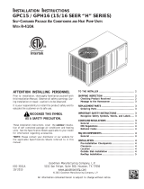
Page 8 of 27
Return opening
Drain access
Supply opening
High voltage knockout
Low voltage knockout
access door
Control panel door
Heater package access panel
Compressor
Heater package knockout
A
E
C
D
L
W
B
F
Condenser air
Condenser air
intake grille
intake grille
access door
Blower motor
Condenser fan
G
47 11/16"
H
Unit Dimension Chart
MIS-2142 A
A C B C H (height) L (length) W (width) D E F G
PA/PH1324,1330,1336 5.875 32.875 13.875 32.875 26.25 53.25 38.125 23.25 1.125 1.375 35.625
PA/PH1342,1348,1360 9.875 37.875 15.875 37.875 33.25 55.25 42.375 30.25 1.5 2.375 38.125
Unit
Unit General DimensionsSupply Size Return Size Unit Overall Dimensions
FIGURE 1
UNIT DIMENSIONAL DRAWING

Manual 2100-468E
Page 9 of 27
INSTALLATION
LOCATION
GENERAL
The unit must be located outside, or in a well ventilated
area. It must not be in the space being heated or cooled. A
sound absorbing material should be considered if the unit is
to be installed in such a position or location that might
cause transmission of sound or vibration to the living area
or adjacent buildings.
SLAB MOUNTING
In areas where winter temperatures DO NOT go below
32°F for periods over twelve hours, the unit may be slab
mounted at grade level. When installing unit at grade level,
install on a concrete slab at least four inches above finished
grade level. Slab should have a slope tolerance away from
the building structure of at lease ¼ inch per foot, while
being level from side to side. This will prevent ice buildup
under the unit during defrost cycles. Place slab in a
location where runoff water from higher ground will not
collect around unit. See Figure 2.
A minimum of 24 inches should be provided between the
coil inlet and any building surfaces. Provide a minimum of
three feet clearance on the service access side of the unit.
See Figure 3.
When a unit is installed in areas where low ambient
temperatures or strong winter winds exist, it should be
placed so prevailing winter winds are not in direct line with
the heat pump coil. If this is not possible, a wind barrier
should be constructed. Place barrier 24 inches from the
coil inlet side of the unit and in the direction of prevailing
winds. Size barrier at least the same height and width as
the unit. This may be necessary on ground level
installations, also. See Figure 3.
WINTER INSTALLATION BELOW 32°F
In areas where winter conditions go below 32°F for
extended periods, the unit must be elevated above the
mounting surface to prevent snowfall or defrost ice
accumulation from interfering with the operation of the
unit. A minimum of twelve inch elevation is
recommended, while greater elevation may be required for
areas of high snow accumulation. Poured concrete, steel
framework, brick, cement block, etc., can be utilized to
construct a suitable raised mounting platform. See
Figure 4.
TYPICAL INSTALLATIONS
1.
ROOF MOUNTED
– The unit is mounted on a
sturdy base on the roof of the building. Return air to
the unit is brought through a single return grille (grilles
with built-in filters are best since they enable easy
access for filter changing). Return air ducts are
attached to the lower section of the front panel. Supply
air is brought from the unit to attic duct work or to a
furred down hall. Supply air duct is attached to the top
of the front panel.
CAUTION: All outdoor duct work must be thoroughly
insulated and weatherproofed. All attic duct
work must be thoroughly insulated. Two inch
thick insulation with suitable vapor barrier is
recommended for both outdoor and attic runs.
In roof top installation, as in all installations, the heat
pump must be level from side to side. However, the
unit should have a pitch along the length to assure
complete external drainage of precipitation and of
defrost condensate.
2.
CRAWL SPACE
– Duct work installed in crawl
space must be well insulated and provided with a vapor
barrier. In addition, the crawl space must be
thoroughly ventilated and provided with a good vapor
barrier as a ground cover. It is most desirable to install
the unit outdoors rather than inside the crawl space, so
that it will be readily accessible for service. In
addition, it is necessary to dispose of the condensate
from the outdoor coil on the heating cycle, and this is
virtually impossible with the unit installed inside the
crawl space.
3.
SLAB MOUNTED AT GROUND LEVEL
– This
type installation is ideal for homes with a slab floor
construction where a roof mounted unit is not desired.
The supply and return duct work can be run through a
furred closet space.
4.
THROUGH THE WALL
– This type installation
requires a suitable framework to be fabricated capable
of withstanding the unit weight. Normally the unit will
be insulated so as to minimize supply and return duct
work.

Manual 2100-468E
Page 10 of 27
FIGURE 2
SLAB MOUNTING AT GROUND LEVEL
36" min.
24" min.
24" min.
The distance between
1 inch clearance
Access
Air Inlet
Comp-
Nearest Structure
Air Inlet
Supply and Return Ducts
Nearest Structure
Nearest Structure
Building
Control Panel
Access
Control Panel
Access
Heater Package
Access
Blower Service
and
ressor
Blower Motor
Heater Package
Blower
Compressor
from top.
units only).
Condenser fan
and motor access
above fan.
Leave 60" min.
Side
View
View
Top
between duct and
any combustible
material if distance
between outside
wall and unit is less
than 3 feet (needed
on electric heat
MIS-2143 A
Mounting Slab
Ground Level
Package Unit
Supply Duct
from building
Return Duct
requirements.
outside wall and unit
Air Outlet
varies with installation
1/4 inch per foot
slope away
Building
FIGURE 3
AIRFLOW AND SERVICE ACCESS CLEARANCES

Manual 2100-468E
Page 11 of 27
FIGURE 4
ELEVATED MOUNTING PLATFORMS
Both legs must rest
on surface of platform
32°F or lower climate
12" min. if in
48" min.
48" min.
32°F or lower climate
12" min. if in
on surface of platform
Both legs must rest
Platform can be as
shown or solid
Poured concrete,
brick, or block
Metal frame
MIS-2144 A

Manual 2100-468E
Page 12 of 27
AIR FILTERS
Air filters for the return air side of the system are not
provided as part of the various types of applications for these
models, and must be field supplied and installed as part of
the final installation.
Prior thought should be given to return air location and
placement of the air filter(s). The air filter(s) must be of
adequate size and readily accessible to the operator of the
equipment. Filters must be adequate in size and properly
maintained for proper operation. If this is not done,
excessive energy use, poor performance, and multiple
service problems will result. It is impossible to oversize air
filters. Generous sizing will result in cleaner air and coils as
well as lower operating costs and extend the time between
required changes. Table 5 shows minimum filter areas and
recommended filter sizes. Actual filter sizes can vary with
the installation due to single or multiple returns utilizing a
filter/grille arrangement or being placed immediately ahead
of the indoor coil face in the return air duct.
5.
OTHER INSTALLATIONS
– Many other
installations are possible with the packaged heat
pump. No matter what the installation, always
consider the following facts:
A. Insure that the discharge air is not obstructed in
any way so as to cause operation difficulties.
B. The indoor coil drain pan is equipped with a
coupling that must be piped through a condensate
drain trap to a suitable drain.
C. Always mount the unit is such a position that it
may be easily reached for servicing and
maintenance.
D. Insure that the unit is clear so that proper air flow
over the outdoor coil will be maintained.
If this unit is operated in cooling below a 55° outdoor
ambient temperature, the installation of low ambient
controls (CMH-15) to unit is required.
CONDENSATE DRAIN TRAP
It is very important to provide a trap in the condensate
drain line to allow a positive liquid seal in the line and
assure correct drainage from the coil condensate pan.
Install condensate drain trap shown in Figure 5. Use drain
connection size or larger. Do not operate unit without
trap. Unit must be level or slightly inclined toward drain.
With a trap installed on a unit located in an unconditioned
area, water in the trap may freeze. It is recommended that
the trap material be of a type that will allow for expansion
of water when it freezes.
FIGURE 5
CONDENSATE DRAIN TRAP
NOTE: If roof hood accessory is to be used, information
on air filters may be found under that heading in
this manual. Air filters are supplied as part of
that package.
TABLE 5
FILTERS REQUIRED AND SIZE
.oNledoM
retliFmuminiM
aerAeerF
muminiM
eziSdednemmoceR
4231HP
0331HP
6331HP
sehcnIerauqS304
)teeFerauqS8.2(
1x02x41)2(
2431HP
8431HP
0631HP
sehcnIerauqS374
)teeFerauqS3.3(
1x02x61)2(

Manual 2100-468E
Page 13 of 27
THERMOSTATS
See specific wiring information for the different models, heater KWs, and voltages.
TABLE 6
HEAT PUMP THERMOSTATS
IMPORTANT NOTE: Only the thermostat and subbase combinations as shown above will work with this equipment.
The thermostat and subbase MUST be matched, and correct operation can be assured only by proper selection
and application of these parts. The above combinations incorporate the following features: Man-Auto fan
switch, Off-Heat-Cool-Em. Heat Switch.
NOTE: All thermostats specified maintain the reversing valve energized when switched into heating mode (does not
cycle with demand).
TABLE 7
THERMOSTAT WIRE SIZE
tatsomrehTserutaeFtnanimoderP
850-3048
)1511D0225HT(
taeHegats2;looCegats2
elbammargorP-noNcinortcelE
revoegnahclaunaMrootuA
060-3048
)544-0211(
taeHegats3;looCegats3
cinortcelEelbammargorP-noN/elbammargorP
lanoitnevnoCroPH
revoegnahclaunaMrootuA
remrofsnarT
AV
ALF
eriW
eguaG
htgneLmumixaM
teeFnI
553.202
81
61
41
21
54
06
001
061
052

Manual 2100-468E
Page 14 of 27
FIGURE 6
LOW VOLTAGE WIRING
WIRING – MAIN POWER
Refer to the unit rating plate for wire sizing information
and maximum fuse size. Each outdoor unit is marked with
a “Minimum Circuit Ampacity”. This means that the field
wiring used must be sized to carry that amount of current.
If field installed heaters are added to the basic unit, a
second separate power supply circuit will be required. The
heater rating plate located adjacent to the basic unit rating
plate will show the appropriate circuit ampacity fuse size,
etc. (Also see “Electrical Data” on pages 5 and 7.) All
models are suitable for connection with copper wire only.
These instructions must be adhered to. Refer to the
National Electrical Code for complete current carrying
capacity data on the various insulation grades of wiring
material.
The unit rating plate lists a “Maximum Time Delay Fuse”
or “HACR” type circuit breaker that is to be used with the
equipment. The correct size must be used for proper circuit
protection and also to assure that there will be no nuisance
tripping due to the momentary high starting current of the
compressor.
WIRING – 24V LOW VOLTAGE
CONTROL CIRCUIT
Eight (8) wires should be run from thermostat subbase to
the 24V terminal board in the unit. A ten conductor,
18 gauge copper, color-coded thermostat cable is
recommended. The connection points are shown in
Figure 6.
O/B
W2
MIS-2150 A
Low Voltage Wiring
D1
DH
A
AUX
Unit Control Panel
Block
Y
C
GR Y1B
W1 E
LW3
Y1C
GR
Y2 W2
L
LEO/B
RC
R
GC
Y
1120-445
Thermostat Subbase
TH5220D1151
Terminal
Unit 24V
W1
E

Manual 2100-468E
Page 15 of 27
THERMOSTAT INDICATOR LAMPS
The red lamp marked “EM. HT.” comes on and stays on
whenever the system switch is placed in Em. Ht. position.
The green lamp marked “Check” will come on if there is
any problem that prevents the compressor from running
when it is supposed to be.
EMERGENCY HEAT POSITION
The operator of the equipment must manually place the
system switch in this position. This is done when there is a
known problem with the outdoor section, or when the green
“Check” lamp comes on indicating a problem.
TRANSFORMER TAPS
230/208V, 1 phase and 3 phase equipment employ dual
primary voltage transformers. All equipment leaves the
factory wired on 240V tap. For 208V operation, reconnect
from 240V to 208V tap. The acceptable operating voltage
range for the 240 and 208V taps are:
TAP RANGE
240 253 – 216
208 220 – 187
NOTE: The voltage should be measured at the field
power connection point in the unit and while the
unit is operating at full load (maximum amperage
operating condition).
COMPRESSOR CUTOFF THERMOSTAT
and OUTDOOR THERMOSTAT WIRING
Heat pump compressor operation at outdoor temperatures
below 0°F are neither desirable not advantageous in terms
of efficiency. Since most equipment at time of manufacture
is not designated for any specific destination of the country
and most of the equipment is installed in areas not
approaching the lower outdoor temperature range, the
compressor cutoffs are not factory installed.
Outdoor thermostats are available to hold off various banks
of electric heat until needed as determined by outdoor
temperature. The set point of either type of thermostat is
variable with geographic region and sizing of the heating
equipment to the structure. Utilization of the Heating
Application Data and the heat loss calculation of the
building are useful in determining the correct set points.
Refer to Installation Instructions of CMH-14 Outdoor
Thermostat Kit for more information.
FIGURE 7
UNIT 24V TERMINAL BOARD ( 5 — 10 KW)
MIS-2151
D1
Outdoor Fan Motor
Control
Yellow
Yel/Brn
Terminal
Outdoor
Block
Y
C
G
R
Y1
B
DH
Black
Safety
W1
Compressor
Factory Jumper
W2
Yellow
E
W3
Unit Control Panel
Unit 24V
Heat
Brown
Remove
Relay
used as
"Y to Y1"
Yel/Brn
Cutoff
L
Blue
Thermostat
Heat Pump
Control
(Partially Shown)
Low Ambient
Optional Field Wiring
2
1
3
5
1
3
2
4
6
L
Note: Factory set on 60 min.
cycle. Reconnect on 30 min.
for 30 min. cycle or 90 min.
for 90 min. cycle.
SPEEDUPJMPSEN
306090
NC
NO
COM
R
W2
R
Y
CC
L1
C
C
LO
B
RV
SENSOR
OFM

Manual 2100-468E
Page 16 of 27
COMPRESSOR CUTOFF THERMOSTAT
WIRING (5 — 10 KW) (FIGURE 7)
COMPRESSOR CUTOFF THERMOSTAT
WIRING (15 — 20 KW ) (FIGURE 8)
TABLE 9
15 — 20 KW
ledoMWKstloVesahP
A-20331HP510321
A-26331HP510321
B-26331HP510323
A-22431HP510321
C-,B-22431HP51064/0323
A-28431HP510321
C-,B-28431HP51064/0323
A-20631HP510321
C-,B-20631HP51064/0323
TABLE 8
5 — 10 KW
ledoMWKstloVesahP
A-24231HP01,5,00321
A-20331HP01,5,00321
A-26331HP5,00321
B-26331HP9,00323
A-22431HP01,5,00321
C-,B-22431HP9,0064/0323
A-28431HP01,5,00321
C-,B-28431HP9,0064/0323
A-20631HP01,5,00321
C-,B-20631HP9,0064/0323
FIGURE 8
UNIT 24V TERMINAL BOARD ( 15 THROUGH 20 KW)
D1
Control
Optional Field Wiring
Outdoor
DH
Y1
Factory Jumper
Safety
Compressor
Block
Y
C
G
R
used as
B
W1
W3
Yel/Brn
W2
Outdoor Fan Motor
Brown
L
Heat
Unit Control Panel
Unit 24V
Remove
Cutoff
Relay
Yellow
"Y to Y1"
Yel/Brn
Blue
Yellow
E
Terminal
Black
Thermostat
Heat Pump
Control
(Partially Shown)
Low Ambient
MIS-2152
2
1
3
5
1
3
2
4
6
L
Note: Factory set on 60 min.
cycle. Reconnect on 30 min.
for 30 min. cycle or 90 min.
for 90 min. cycle.
SPEEDUPJMPSEN
306090
NC
NO
COM
R
W2
R
Y
CC
L1
C
C
LO
B
RV
SENSOR
OFM

Manual 2100-468E
Page 17 of 27
START UP
These units require R-410A refrigerant and Polyol Ester.
GENERAL:
1. Use separate service equipment to avoid cross
contamination of oil and refrigerants.
2. Use recovery equipment rated for R-410A
refrigerant.
3. Use manifold gauges rated for R-410A (800 psi/250
psi low).
4. R-410A is a binary blend of HFC-32 and HFC-125.
5. R-410A is nearly azeotropic - similar to R-22 and
R-12. Although nearly azeotropic, charge with
liquid refrigerant.
6. R-410A operates at 40-70% higher pressure than
R-22, and systems designed for R-22 cannot
withstand this higher pressure.
7. R-410A has an ozone depletion potential of zero,
but must be reclaimed due to its global warming
potential.
8. R-410A compressors use Polyol Ester.
9.
Polyol Ester
oil is hygroscopic; it will rapidly absorb
moisture and strongly hold this moisture in the oil.
10. A liquid line dryer must be used - even a deep
vacuum will not separate moisture from the oil.
11. Limit atmospheric exposure to 15 minutes.
12. If compressor removal is necessary, always plug
compressor immediately after removal. Purge with
small amount of nitrogen when inserting plugs.
TOPPING OFF SYSTEM CHARGE
If a leak has occurred in the system, Bard Manufacturing
recommends reclaiming, evacuating (see criteria above),
and charging to the nameplate charge. Topping off the
system charge can be done without problems.
With R-410A, there are no significant changes in the
refrigerant composition during multiple leaks and
recharges. R-410A refrigerant is close to being an
azeotropic blend (it behaves like a pure compound or
single component refrigerant). The remaining refrigerant
charge, in the system, may be used after leaks have
occurred and then “top-off” the charge by utilizing the
charging charts on the inner control panel cover as a
guideline.
REMEMBER: When adding R-410A refrigerant, it must
come out of the charging cylinder/tank as a liquid to avoid
any fractionation, and to insure optimal system
performance. Refer to instructions for the cylinder that is
being utilized for proper method of liquid extraction.
SAFETY PRACTICES:
1. Never mix R-410A with other refrigerants.
2. Use gloves and safety glasses,
Polyol Ester
oils can
be irritating to the skin, and liquid refrigerant will
freeze the skin.
3. Never use air and R-410A to leak check; the
mixture may become flammable.
4. Do not inhale R-410A – the vapor attacks the
nervous system, creating dizziness, loss of
coordination and slurred speech. Cardiac
irregularities, unconsciousness and ultimate death
can result from breathing this concentration.
5. Do not burn R-410A. This decomposition
produces hazardous vapors. Evacuate the area if
exposed.
6. Use only cylinders rated DOT4BA/4BW 400.
7. Never fill cylinders over 80% of total capacity.
8. Store cylinders in a cool area, out of direct
sunlight.
9. Never heat cylinders above 125°F.
10. Never trap liquid R-410A in manifold sets, gauge
lines or cylinders. R-410A expands significantly
at warmer temperatures. Once a cylinder or line is
full of liquid, any further rise in temperature will
cause it to burst.
START UP NOTES
For improved start up performance, wash the indoor coil
with dishwasher detergent.

Manual 2100-468E
Page 18 of 27
START UP AND OPERATION
THREE PHASE SCROLL COMPRESSOR
START UP INFORMATION
(Models PH13362-B, PH13422-B, -C; PH13482-B,
-C; PH13602-B, -C)
All units with three phase scroll compressors are equipped
with a three phase line monitor to prevent compressor
damage due to phase reversal.
The phase monitor in this unit is equipped with two LED’s.
If the “Y” signal is present at the phase monitor and phases
are correct, the green LED will light.
If phases are reversed, the red fault LED will be lit and
compressor operation is inhibited.
If a fault condition occurs, reverse tow of the supply leads
to the unit. Do not reverse any of the unit factory wires as
damage may occur.
SEQUENCE OF OPERATION
BLOWER ONLY – When the “Fan” switch on the room
thermostat is placed in the “On” position (circuit R-G
makes), the blower will energize and run until the “Fan”
switch is placed back into the “Auto” position. This will
allow for constant air circulation at a lower airflow during
times when the unit is not in operation for cooling or
heating.
COOLING – On a call for cooling from the room
thermostat (circuit R-Y makes), the blower will energize
(circuit R-G is automatic when R-Y makes) as well as the
compressor, and outdoor fan motor. Note that if the “Fan”
switch on the room thermostat is in the “On” position and
the blower is already in operation, then the motor will ramp
up to the required speed for cooling.
HEATING (1st Stage) – On a call for heating from the
room thermostat (circuit R-Y&B makes), the blower will
energize (circuit R-G is automatic when R-Y makes) as
well as the compressor, outdoor fan motor, and reversing
valve solenoid coil. This will place the system into heat
pump operation to maintain the thermostat set temperature.
Note that if the “Fan” switch on the room thermostat is in
the “On” position and the blower is already in operation,
then the motor will ramp up to the required speed for
heating.
HEATING (1st Stage Defrost) – During the defrost
cycle, the heat pump control will energize electric heaters,
if installed, (circuit R-W2 makes), allowing room
temperature to be maintained during heat pump defrost
operation.
HEATING (2nd Stage) – If the operation of the heat
pump will not maintain the set room temperature, then the
thermostat will call for additional heat from electric heaters
to help maintain the set temperature. On a call for second
stage heating from the room thermostat (circuit R-W2
makes), backup electric heaters will be energized if
installed.
HEATING (Em Heat) – When the room thermostat is
placed in the “Em Heat” position (circuit R-E makes), the
blower and electric heaters, if installed, will energize on
second stage heat (circuit R-W2&W3 makes), with the
compressor and outdoor fan motor locked out of operation.

Manual 2100-468E
Page 19 of 27
MIS-1191
DEFROST CYCLE
The defrost cycle is controlled by temperature and time on
the solid state heat pump control. See Figure 9.
When the outdoor temperature is in the lower 40°F
temperature range or colder, the outdoor coil temperature is
32°F or below. This coil temperature is sensed by the
defrost sensor mounted near the bottom of the outdoor coil.
Once the Heat Pump Control board sees the resistance of
the defrost sensor has been below the resistance of 34545
(30°F) for 60 minutes of accumulated run time. The Heat
Pump Control Board will start the defrost cycle by de-
energizing the reversing valve and condenser fan. It will
also send a signal to W2 to energize the electric heat if
equipped. When the Heat Pump Control Board reads the
resistance of the defrost sensor has risen to 16547 (57°F) or
it has been in defrost for 10 minutes the defrost cycle will
terminate.
After 30 minutes at 30°F or below, the heat pump control
will place the system in the defrost mode.
During the defrost mode, the refrigerant cycle switches
back to the cooling cycle, the outdoor motor stops, electric
heaters are energized, and hot gas passing through the
outdoor coil melts any accumulated frost. When the
temperature rises to approximately 57°F the coil sensor will
send a signal to the heat pump control which will return the
system to heating operations automatically.
If some abnormal or temporary condition such as a high
wind causes the heat pump to have a prolonged defrost
cycle, the heat pump control will restore the system to
heating operation automatically after 10 minutes.
There are three settings on the heat pump control – 30
minute, 60 minute and 90 minute. Models are shipped
wired on the 60 minute setting for greatest operating
FIGURE 9
HEAT PUMP CONTROL BOARD
economy. If special circumstances require a change to
another time, remove wire connected to terminal 60 and
reconnect to desired terminal. Refer to Figure 9. The
manufacturer’s recommendation is for 60 minute defrost
cycles.
There is a cycle speed up jumper on the control. This can
be used to reduce the time between defrost cycle operation
without waiting for time to elapse.
Use a small screwdriver or other metallic object, or another
1/4 inch QC to short between the SPEEDUP terminals to
accelerate the HPC timer and initiate defrost.
Be careful not to touch any other terminals with instrument
used to short the SPEEDUP terminals. It may take up to 10
seconds with the SPEEDUP terminals shorted for the
speedup to be completed and the defrost cycle to start.
As soon as the defrost cycle kicks in remove the
shorting instrument from the SPEEDUP terminals.
Otherwise the timing will remain accelerated and run
through the 1 minute maximum defrost length sequence in
a matter of seconds and will automatically terminate the
defrost sequence.
There is an initiate defrost jumper (sen jump) on the control
that can be used at any outdoor ambient during the heating
cycle to simulate a 0° coil temperature. This can be used to
check defrost operation of the unit without waiting for the
outdoor ambient to fall into the defrost region.
By placing a jumper across the SEN JMP terminals (a 1/4
inch QC terminal works best) the defrost sensor mounted
on the outdoor coils is shunted out and will activate the
timing circuit. This permits the defrost cycle to be checked
out in warmer weather conditions without the outdoor
temperature having to fall into the defrost region.
In order to terminate the defrost test in the SEN JMP
jumper must be removed. If left in
place too long the compressor could
stop due to the high pressure control
opening because of the high pressure
condition created by operating in the
cooling mode with outdoor fan off.
Pressure will rise fairly fast as there is
likely no actual frost on the outdoor coil
in this artificial test condition.
There is also a 5 minute compressor
time delay function built into the HPC,
This is to protect the compressor from
instances it is helpful to the service
technician to override or speed up this
timing period, and shorting out the
speedup terminals for a few seconds can
do this.

Manual 2100-468E
Page 20 of 27
TROUBLESHOOTING
motpmySsesuaCelbissoP riapeR/kcehCotwoH&tahW
lliwrosserpmoC
gnitaeh(tratston
)gniloocro
CotRmorfV42rofkcehC
lortnocpmuptaehehtno
tupniremrofsnartkcehcdnaremrofsnartotdraobmorfgniriwkcehc,RtatneserptonsiV42fI
ecalperdnaesuacenimreted,tuptuoV42onsahremrofsnartfI.egatlovtuptuodna
.remrofsnart
CotYmorfV42rofkcehC
pirtslanimretegatlovwolno
)deppiuqefi(tatsomrehtroodtuo,gniriwtatsomrehtdnatatsomrehtkcehc,tneserptonsiV42fI
oteunitnoctneserpsiV42fI.)sledomesahp-3emosnodesu,deppiuqefi(rotinomesahp
.petstxen
otCmorfV42rofkcehC
lortnocpmuptaehnoCC
ehtpmuj,tneserptonsiV42fI.rotcatnocrosserpmocecalperro/dnakcehc,tneserpsiV42fI
1LotCmorfV42rofkcehctratstonseodrosserpmocfI.sdnoces01roflanimretpudeeps
.lortnocpmuptaehehtno
tuokcolrosserpmoC woldnahctiwserusserphgihehtkcehc,lortnocpmuptaehehtfo1LtatneserptonsiV42fI
tiucricytefasehT.slanimretdnagniriwdetaicossalladna)deppiuqefi(yalerssapyberusserp
eht,nepoerayalerssapyberusserpwolrohctiwserusserphgihehtfI.tiucricdesolcasi
otnodnafforewopelcyC.tnenopmocevitcefedecalpeR.rosserpmocehttuokcollliwlortnoc
.yaledemitetunim-5edirrevootsdnoces01rofslanimretpudeepspmuJ.tuokcolteser
lortnocpmuptaehevitcefeD neebsahyaledemiteht,lortnocpmuptaehehtno1LotCdna,YotCmorftneserpsiV42fI
.lortnocpmuptaehehtecalper,CCtatneserpsiV42ondnaderipxeroneddirrevo
rotomroodtuonaF
nurtonseod
gnitaehrognilooc(
gnirudtpecxe
)tsorfed
evitcefedlortnocpmuptaeH )CN-moC(.lortnocpmuptaehnoyalernafssorcakcehC
.lortnocpmuptaehecalpeR
evitcefedrotoM .rotomecalpeR.gnidniwrotomdetrohsroneporofkcehC
evitcefedroticapacrotoM .roticapacecalpeR.roticapacdetrohsroneporofkcehC.gnitarroticapackcehC
evlavgnisreveR
ezigrenetonseod
)ylnognitaeh(
evitcefedlortnocpmuptaeH.C-BdnaC-VRneewtebV42rofkcehC
.gniriwtiucriclortnockcehC.1
lortnocpmuptaehecalpeR.2
dionelosevlavgnisreveR
evitcefedlioc
.liocdetrohsroneporofkcehC
.liocdionelosecalpeR
ogtonlliwtinU
tsorfedotni
)ylnognitaeh(
taehrorosneserutarepmeT
evitcefedlortnocpmup
NES"dnaslanimret"PUDEEPS"ssorcarepmujdnadraobmorfrosneserutarepmettcennocsiD
.etunimenonihtiwelcyctsorfedahguorhtogottinuehtesuacdluohssihT.slanimret"PMJ
.rosneserutarepmetecalper,elcyctsorfedhguorhtseogtinufI.1
.lortnocpmuptaehecalper,elcyctsorfedhguorhtogtonseodtinufI.2
emoctonlliwtinU
tsorfedfotuo
)ylnognitaeh(
taehrorosneserutarepmeT
.evitcefedlortnocpmup
.lanimret"PUDEEPS"ssorcarepmuJ
.etunimenonihtiwtsorfedfotuoemocottinuehtesuacdluohssihT
.rosneserutarepmetecalper,elcyctsorfedfotuosemoctinufI.1
.lortnocpmuptaehecalper,elcyctsorfedfotuoemoctonseodtinufI.2
TROUBLESHOOTING
SOLID STATE HEAT PUMP CONTROL
TROUBLESHOOTING PROCEDURE
NOTE: A thorough understanding of the defrost
cycle sequence is essential. Review that section
earlier in this manual prior to troubleshooting
the control.
1. Turn on AC power supply to unit.
2. Turn thermostat blower switch to “fan on” – the
indoor blower should start. (If it doesn’t,
troubleshoot indoor unit and correct problem.)
3. Turn thermostat blower to “auto” position. Indoor
blower should stop. NOTE: Many models have a
1-minute blower time delay on “off” command;
wait for this to time-out.
4. Set system switch to “heat” or “cool”. Adjust
thermostat to call for heat or cool. The indoor
blower, compressor and outdoor fan should start.
NOTE: If there was no power to 24 volt transformer,
the compressor and outdoor fan motor will
not start for 5 minutes. This is because of
the compressor short cycle protection.
/