Page is loading ...

Texmate, Inc. Tel. (760) 598-9899 • www.texmate.com Page 1
SM-35X manual (SM03)
General Features Specifications
SM-Series
The SM-35X is one of Texmate's new SM-series meter range.
This range, which includes meters with LCD and LED displays,
offers many unique features designed to simplify installation,
calibration and scaling. All SM-35 and SM-35X meters are
pin-compatible, which enables LED and LCD meters to be
interchanged within the same panel without necessitating wir-
ing or panel cutout changes.
All SM-series meters are 5 V DC powered with bipolar sin-
gle-ended inputs. The meters feature Display Hold, Display
Test and Auto-Polarity indication. The polarity indication may be
disabled or reversed by repositioning jumper clips on internal
header pins. The SM-series of meters are designed to be user
scalable to almost any engineering unit of readout. On-site
scaling and recalibration is facilitated by multi-turn potentiome-
ters that provide continuous fine and coarse adjustment within
each of the three header-programmable full scale ranges.
The three ranges provided with the SM-35X (LCD display ) and
the SM-35 (LED display) are 2 V, 20 V, and 200 V full scale and
both of these meters can be ordered with an optional zero-off-
set adjustment potentiometer.
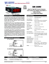
SM-35MV (LED display) is specially designed for low voltage
inputs and provide three header-programmable input ranges of
20 mV, 200 mV, and 200 V full scale. SM-35MV has zero-offset
adjustment potentiometers as a standard feature and a unique
constant current power supply that eliminates any ground loop
noise.
Input Configuration: ... Single-ended, with optional provision
to offset the zero of the reading
displayed
Input Impedance: ........1MΩ minimum
Full Scale Ranges: .....±2 V DC (Standard Range) ±20 V DC
±200 V DC (All ranges are header
selectable)
A/D Converter: ............12 Bit Dual Slope
Accuracy: ....................±(0.05% of reading + 2 digits)
Temp Coefficient: ....... 100ppm/°C typical
Warmup Time: ............One minute to specified accuracy
Conversion Rate: ........3 readings per second
Display:........................0.48" Liquid Crystal Display (LCD);
"Display Hold" & Dummy Zero
Decimal Selection: .....User programmable to 3 positions
Polarity: .......................Automatically displays both “+” or “–”
signs; header programmable polarity
disable and reversal
Over-range Indication: When input exceeds full scale on
any range being used, the most
significant “1” digit and “+” or “–”
symbol is displayed with all other
active digits blanked
Power Supply: ............+4.5 to +5.5V DC at 5mA
Operating Temperature: –20˚C to +60˚C
Storage Temperature: -20˚C to +70˚C
Relative Humidity: ......95% (non-condensing)
Case Dimensions: ......Bezel (2.755”W x 1.170”H)
69.68mmW x 29.72mmH Depth
behind bezel (3.315”) 84.2mm Plus
(0.685”) 17.4mm for connector
Weight: ........................88 gms (3.1 oz)
143 gms (5 oz) when packed
SM-35X
Typical Application Connections
SM-35
Offset (optional)
Span Fine
Span Coarse
Range
Select
Header
Polarity
Display
Header
200V
20V
2V
SIG
+5 V
GND
Vin
0 to ±200 V DC
5 V DC
Recommended
Analog Ground return path
DC VOLTMETER
SM-Series LED Displays SM-Series LCD Displays
Multirange 2V, 20V & 200V DC
Easily-Scaled 5V DC Powered
3 1/2 Digit Panel Meter
0.48” LCD Display
SM-35 ...............
3.5 digit Red LED, 2/20/200VDC, 5VDC Pwr
SM-35MV ...........
3.5 digit Red LED, 0.02/0.2/2VDC, 5VDC Pwr
SM-35X .............
3.5 digit LCD, 2/20/200VDC, 5VDC Pwr

Texmate, Inc. Tel. (760) 598-9899 • www.texmate.comPage 2 SM-35X manual (SM03)
+ 5 V – 5 V
Input HI
Reference
Analog
Common
Input LO
Hold
Test
12 Bit A/D and
Display Driver
Polarity
1X.XX
COM
1.XXX
DP Common
1X•XX DP
1•XXX DP
220 Polarity
Header
+–
Rev
To Display
Clock
1M
1M
Optional
Zero Pot
TEST
HOLD
SIG +5V
Hold
Test
+5V DC
Input HI
50K
470K
Span
Fine Pot
4K75
4K3
1K
1K
+5V
+1.25V
Input
Protection
Circuit
48KHz
Clock
Circuit
–5V
Generation
Circuit
–5V
Range
Select
Header
Span
Coarse
Pot
2V
0.1
20V
200V
GND
+5V
Po
wer GND
0.48" Display
1XX.X
COM
ZERO
DP Common
1XX•X DP
RHS Zero
Back Plane
Inverter
BP
BP
BP
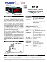
Functional Diagram
Connector Pinouts
Component Layout
Signal Conditioning Components
and 9 are recommended when using edge connectors with the
meter to minimize ground loop effects.)
Pin L - Display Hold Input (CMOS compatible): If Pin L is left
open, the meter will operate in a free-running mode. While Pin
L is connected to +5 V DC Power Supply Input Pins 6 and 7,
the meter will latch up; A/D conversions will continue but the
display will not be updated until Pin L is released.
Pins 4 and 5 - Signal High Input: Signal inputs for all voltage
ranges are applied to these pins. Maximum overvoltage pro-
tection is ±400 V DC or 280 V AC. See CAUTION:ELECTRIC
SHOCK HAZARD on rear page.
Pins 6 and 7 - +5 V DC System Power Input: The meter
requires a regulated low-ripple 5 V DC power supply applied to
these pins.
Pins 8 and 9 - Signal Low Input: Signal low input of the
analog to digital converter circuits (Note: When measuring input
signals (on the 2 V range) that are not isolated from the +5 V
DC supply used to power the meter, a ground loop can be cre-
ated that will cause the least significant digit to exhibit errors
and instability. To avoid this problem the ground return path of
the analog signal should be connected to the power supply
ground only at the Signal Low Input Pins 8 and 9 of the meter.)
Pin 10 - Display Test Input: All numeric display segments will
operate when Pin 10 is connected to +5 V DC Power Supply
Input Pins 6 and 7. CAUTION: The Display Test function is
only intended for momentary operation. Continuous application
of Display Test will, in time, damage the display.
Pin A,C, 1 and 3 - Decimal Select and Dummy Zero: Decimal
points and dummy zero may be blanked as required by careful-
ly scraping off the fine tracks linking these pins to Decimal
Select Common using a pair of pliers or a small screwdriver
blade. Re-connect either by linking the appropriate pins on the
connector or by solder-bridging the junctions located on the PC
board edge fingers. CAUTION: Do not connect either the
dummy zero or the decimal select to power supply ground.
Although the dummy zero and decimals will become activated
when their select pins are grounded, this improper connection
will eventually cause permanent damage to the display.
Pins B and 2 - Decimal Select Common: Common return pins
for decimal point selection (see CAUTION above.)
Pins J and K - Power Supply Ground: Power supply ground
return (Note: Separate connections to Pins J and K and Pins 8
1.XXX
COM
1X.XX
SIG
1XX.X
COM
Zero
+5 V
GND GND
TEST HOLD
Decimal Select - 1
Decimal Select Common - 2
Decimal Select - 3
Signal High Input 4
5
6
7
8
9
+5 V DC Power
Supply Input
Signal Low Input
Display Test Input - 10
A - Decimal Select
B - Decimal Select Common
C - Zero
Power Supply Ground
L - Display Hold Input
J
K
Fine "Scrape Off" Tracks Solder Junction
1
A
2
B
3
C
45678910
DE FH JKL
Offset Span Fine Span Coarse
1
A
2
B
3
C
45678910
DE FH JKL
Offset (Optional) Span Fine Span Coarse
For most applications where it is not necessary to activate
Display Hold, Display Test, or remotely change the selected
decimal point and dummy zero, the three screw terminal blocks
supplied with the meter can be used to connect Signal Low
Input and Power Supply Ground (joined on the one terminal),
Signal High Input and +5 V DC Power Input. For other applica-
tions, the Texmate SM-35X interconnects by means of a stan-
dard PC board edge connector having two rows of 10 pins
each, spaced on 0.156" centers. Connectors are available from
Texmate, or from almost any connector manufacturer.
REAR OF METER WITH PCB EDGE CONNECTOR MOUNTED
(For mounting of screw terminal blocks see below) Polarity Display Header
Range Select Header
SPAN Coarse Potentiometer (Pot)
The 15 turn SPAN Coarse pot is on the right
side (as viewed from the back of the meter).
Typical adjustment is 100% of the input signal
range.
SPAN Fine Potentiometer (Pot)
The 15 turn SPAN Fine pot is on the left (as
viewed from the back of the meter). Typical
adjustment is 10% of the input signal range.
RANGE SELECT Header
Range values are marked on the PCB. Three
positions are provided. After selecting a new range
with the single jumper clip, recalibration is required.
DC mV
50
100
200
50
100
200
CAUTION: This meter employs high impedance CMOS inputs. Although internal
protection has been provided for several hundred volt overloads, the meter will
be destroyed if subjected to the high kilovolts of static discharge that can be
produced in low humidity environments. Always handle the meter with ground protection.
Zero Offset
(optional) Span Fine Span Coarse
ZERO Potentiometer (Pot) Optional
The Optional ZERO pot when installed is to the
left of the SPAN pots (as viewed from the back
of the meter). Typically it enables the displayed
reading to be offset ±1000 counts.

Texmate, Inc. Tel. (760) 598-9899 • www.texmate.com Page 3
SM-35X manual (SM03)
Calibration Procedure
CAUTION - ELECTRICAL SHOCK HAZARD See Below.
1) Select the F.S. input voltage range by re-positioning the jumper clip
on the range select header as indicated by the voltages marked on the
PCB.
2) Short Signal High Input Pins 4 & 5 to Signal Low Input Pins 8 & 9.
3) Adjust Zero Offset until the display reads zero.
4) Apply F.S. voltage.
5) Adjust Span Coarse & Span Fine controls; clockwise increases the
displayed reading.
6) Adjust Zero Offset to offset the zero reading as required.
(Re-calibration must be performed after changing ranges).
Normal
Disabled
Reversed
Polarity Display Header
This header allows the Polarity indication to be
displayed normally, displayed reversed or to be
disabled completely.
CAUTION - ELECTRICAL SHOCK HAZARD
All internal parts of the meter may
be at the same electrical potential as the input signal and power supply. Do
not reposition the signal conditioning components when input voltages are
applied. When measuring dangerously high input voltages, extreme care must be
taken to insulate the connector pins as well as all metal parts of the meter. A suit-
able high voltage warning notice should be affixed to those meters where there is
any possibility that the meter could be removed from its case, or the internal com-
ponents accessed, concurrent with the existence of a high voltage input signal.
!
PCB Edge Connector
A standard 20-pin edge con nec tor (two rows of 10 pins on
0.156" centers) is used to connect the SM-35 meter. Order part
no. CN-L10.
PCB Edge Connector
Push-On Screw Terminals
They provide the greatest convenience and ease of use
Texmateʼs exclusive optional Push-On Connectors combine an
edge card connector and a 10 position screw terminal block.
Push-On Connectors are ordered preconfigured for each spe-
cific power supply voltage and each optional power supply
available for the SM-Series.
Part Number: CN-PUSH/SM
Signal Conditioning Components (continued) Decimal Point Selection
The meter is shipped from the factory with all
the decimal points on. To turn off un wanted
decimals, use a pair of long-nosed pliers to
scrape off the fine tracks connecting decimals
to decimal select common (alternatively, use a
scalpel or small screwdriver). Re con nect by
soldering where shown.
RE-BRIDGE HERE
TB-Kit Screw Connectors
Texmate’s individual screw ter mi nal blocks offer a convenient
al ter na tive to edge connectors for many ap pli ca tions, allowing
com plete in stal la tion, con figu ra tion and calibration with out the
need for soldering.
Slide each terminal block over the PCB until the hole aligns. Insert
the re tain ing screw to secure.
Each kit includes: 3 plastic blocks with metal contacts, 4 screws
with spade connectors, 1 metal contact and 3 quick disconnects.
Part Number : TB-KIT
Meters in Dashboard Case Enclosure
CM-35XTL ...... Less than 1V DC loop drop
and 1 Joule energy storage
CM-35XT ....... Economical 4-20mA
loop-powered meter
SP-35X .......... Signal Power DC voltage
measurement from 5.0V DC to 199.9V DC
PM-45X ......... 4.5 digit 0.48” LCD DPM
PM-45XU .......
Lower cost version of PM-45X
PM-45L ......... 4.5 digit 0.4” LED DPM
PM-45LU........
Lower cost version of PM-45L
PS-505 .......5V DC Regulated
Power Supply, 0.5A Output
PS-510 .......5V DC Regulated
Power Supply, 1A Output
AM-20 ........... 20 segment LED bargraph,
5V DC power
*Not Included

Texmate, Inc. Tel. (760) 598-9899 • www.texmate.comPage 4 SM-35X manual (SM03)
SM Case Dimensions and Panel Cutouts
Ordering Information
Standard Options for this Model Number
Part Number Description
BASIC MODEL NUMBER Includes plug in type screw terminals, stan-
dard display and standard power supply unless optional versions are
ordered.
SM-35X ..............3.5 digit LCD, 2/20/200VDC, 5VDC Pwr
Special Options and Accessories
Part Number Description
SPECIAL OPTIONS
(Specify Inputs & Req. Reading
)
ZR .........
Range Change from Standard Range shown in BOLD type
V0-50K ....... Zero offset potentiometer 50k ...............
ZRS-SMUM....
Non-Std Range and/or Scale Changes for SM-35 series
ACCESSORIES
CN-L10 ....... Edge Connector with Solder eyelet, 10 Pin Dual
CN-PUSH/SM.. Push-0n Screw Terminal Block Connector .....
TB-KIT.......... Terminal Block Connector Kit (3) ...............
SL.CASERED.. Slim Bezel Case, Red Faceplate w/Mtg Hrdwre
PS-505 . . . . . . . 5V DC Regulated Power Supply, 0.5A Output ..
PS-510 . . . . . . . 5V DC Regulated Power Supply, 1A Output ...
WARRANTY
Texmate warrants that its products are free from defects in material and workmanship under
normal use and service for a period of one year from date of shipment. Texmate’s obligations
under this warranty are limited to replacement or repair, at its option, at its factory, of any of the
products which shall, within the applicable period after shipment, be returned to Texmate’s
facility, transportation charges pre-paid, and which are, after examination, disclosed to the
satisfaction of Texmate to be thus defective. The warranty shall not apply to any equipment
which shall have been repaired or altered, except by Texmate, or which shall have been sub-
jected to misuse, negligence, or accident. In no case shall Texmate’s liability exceed the original
purchase price. The aforementioned provisions do not extend the original warranty period of
any product which has been either repaired or replaced by Texmate.
USER’S RESPONSIBILITY
We are pleased to offer suggestions on the use of our various products either by way of printed
matter or through direct contact with our sales/application engineering staff. However, since we
have no control over the use of our products once they are shipped, NO WARRANTY
WHETHER OF MERCHANTABILITY, FITNESS FOR PURPOSE, OR OTHERWISE is made
beyond the repair, replacement, or refund of purchase price at the sole discretion of Texmate.
Users shall determine the suitability of the proDXct for the intended application before using,
and the users assume all risk and liability whatsoever in connection therewith, regardless of
any of our suggestions or statements as to application or construction. In no event shall
Texmate’s liability, in law or otherwise, be in excess of the purchase price of the product.
Texmate cannot assume responsibility for any circuitry described. No circuit patent or software
licenses are implied. Texmate reserves the right to change circuitry, operating software, speci-
fications, and prices without notice at any time.
SM-35X Technical Manual Copyright © 2020 Texmate Inc. All rights reserved.
Published by: Texmate Inc. USA. Information in this Technical Manual is
subject to change without notice due to correction or enhancement. The
information described in this manual is proprietary to Texmate, Inc. and may
not be copied, reproduced or transmitted, in whole or in part, in connection
with the design, manufacture, or sale of apparatus, device or private label
product without the express written consent of Texmate, Inc.
1934 Kellogg Ave., Carlsbad, CA 92008
Tel: 1-760-598-9899 • 1-800-TEXMATE
Fax: 1-760-598-9828 • Email: [email protected]
Case Dimensions
TOP VIEW
FRONT VIEW
PANEL CUTOUT SIDE VIEW
16.82mm
0.662in
29.60mm
1.165in
14.50mm
0.571in
64.77mm
2.550 in
24.64mm
0.970in
69.90mm
2.752in
option metal
screw mounting clip
102.36mm
4.030in
84.50mm
3.330in
Edge connector
When extra panel mounting
tightness is required, optional
Screw Mounting Clips can be
purchased seperately and attach
to the sliding mounting side clips
8.50mm
0.335in
2.50mm
0.098in
/