Page is loading ...

NOTE: the high-frequency output of this
sensor is <0.2mW- that is just one 5000 of the
transmission power of a mobile phone or the
output of a microwave oven.
Transmission power<0.2mW
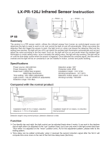
LX-MV-360S10-A is a moving object sensor that can detect range of 360° and it’s working frequency is
5.8G.The advantage of this product is stable working state (stable working temperature: -15°C~+70°C),
LX-MV-360S10-A adopts a microwave sensor(high-frequency output<0.2mW),so that it is safe and performs
better than infrared sensor.
th
Power source: 90-240V/AC
Power frequency: 50/60Hz
Transmission power: <0.2mW
Rated load: Detection angle: 360°
Detection range: 2m-5m-8m-10m (radii.), adjustable
Time setting: 6sec-1min-3min-5min-10min-15min,adjustable
Light-control: <10LUX-100LUX-300LUX-2000LUX,adjustable
Power consumption: approx.0.5W
Working temperature: -15°C~+70°C
1200W/5A,Max,tungsten(cosφ=1)(220-240V/AC)
300W/2.5A,Max,fluorescent(cosφ=0.5)(220-240V/AC)
600W/5A,Max,tungsten(cosφ=1)(100-130V/AC)
150W/2.5A,Max,fluorescent(cosφ=0.5)(100-130V/AC)
Installation sit: ceiling mounting
HF system: 5.8GHz CW electric wave,ISM band
LX-MV-360S10-A Microwave Sensor Instruction
Specifications
Utilizing field and introduction
Sensor information
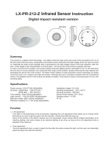
Sensing angle adjustment range
Height of installation2.5~3.5M
(Height of installation2.5~3.5M)
360º
Min:2mMin:2m Max:10m
Max:10m
2.5-3.5m
Sensing distance adjustment range
mm
mm
(Transparent)(Translucence)

Warning!
When you are drilling ,please make sure
you wear glasses and dust masks to
prevent the dust fly into the nose and throat
causing unnecessary trouble.
fig.1 fig.2 fig.3
fig.4
4. Put the power wire and load wire through the base holes(see fig.5);
5.
Cover cover into buckle
(see fig.6);
1. Through the buckle under cover(see fig.1)(fig2)
2.Hold base against the Ceiling and mark drill holes,
paying attention to any existing wiring in the Ceiling;
3. Drill the holes, insert wall plugs (6mm dia.);(see fig.4);
Parameter setting
Shown as chart below:By setting the S1, S2 ,S3 ,S4,S5 to set the delay time of products,by setting S6,S7 to
set the detection range of products, by setting the S8,S9,S10 to set the light-control of products.
TIME:S1,S2,S3,S4,S5 SENS:S6,S7 LUX:S8,S9,S10
fig.6fig.5
base holes
AC Power
L
L’
N
Installation
1
0

If you want LX-MV-360S10-A to detect small zone, you can just adjust the sense sliding controller SENS to the
range that you need (You may need to adjust some times untill you think it is suitable).If you want that the light
can be turned on when the circumstance luminance is under some value, you can just adjust the sliding
controller LUX (The working luminance sliding controller) to select the luminance value (You may need to
adjust some times untill you think it is suitable).
S1 S2 S3 S4 S5 Time setting
00000 15min
100 0 0 10min
010 0 0 5min
001 0 0 3min
000 1 0 1min
000 0 1 6sec
S6 S7 Detection range
1 1 10m
1 0 8m
0
0 0
1 5m
2m
Time setting
Detection range setting (sensitivity)
The light can be set to stay ON for any period of time between approx. 6sec and a maximum of 15min. Any
movement detected before this time elapse will re-start the timer. It is recommended to select the shortest time
for adjusting the detection zone and for performing the walk test.Pull switch to the ON position as "1", pull
switch to the OFF position as "0”, switch location and detection range of the corresponding table is as follows:
Detection range is the term used to describe the radii of the more or less circular detection zone produced on
the ground after mounting the sensor light at a height of 2.5m, pull switch to the ON position as "1", pull switch
to the OFF position as "0”, switch location and detection range of the corresponding table is as follows:
TIME:S1,S2,S3,S4,S5
SENS:S6,S7
S8 S9 S10 Light-control
0 0 1 2000LUX
010300LUX
100100LUX
0 0 0 <10LUX
Light-control setting
The chosen light response threshold can be infinitely from approx. 10-2000lux, pull switch to the ON position
as "1", pull switch to the OFF position as "0”, switch location and detection range of the corresponding table is
as follows:
LUX:S8,S9,S10
ATTENTION:When use this product, please adjust the sensitivity to an appropriate position
you need, please do not adjust the sensitivity to maximum, to avoid the product does not
work normally caused by wrong motion.Because the sensitivity is too high easily detect the
wrong motion by wind blowing leaves & curtains, small animals, and the wrong motion by
interference of power grid & electrical equipment. All those lead the product does not work
normally !
When the product does not work normally, please try to lower the sensitivity appropriately,
and then test it.
1
0
1
0
1
0

1. Being installed in the rocking object will lead to misoperation.
2. The shaking curtain which is blown by wind will lead to misoperation, please select the suitable installed
place.
3. Being installed in the place where the traffic is busy will lead to misoperation.
4. It will lead to misoperation when there are sparks produced by some equipment nearby.
Warning!
The following situation will lead to misoperation
Troubleshooting
Malfunction Cause Remedy
·wrong light-control setting selected ·Adjust setting
·load faulty ·Change load
The load will not work
·mains switch OFF ·Switch ON
The load work always ·continuous movement in the detection
zone
·Check zone setting
·the sensor not mounted for detecting
movement reliably
·Securely mount enclosure
The load work without any
identifiable movement
·movement occurred, but not identified
by the sensor(movement behind wall,
movement of a small object in immediate
lamp vicinity etc.)
·Check zone setting
The load will not work despite
movement
·rapid movements are being suppressed
to minimize
malfunctioning
the
zone you have set is too small
·Check zone setting
detection
or
Warning!
The detection distance may multiply for the reflection on microwave electromagnetic field by
the metal or glass materials. Thus, lower the sensitivity to reach the appropriate detection
distance. Never turn the SENS knob to the maximum value to avoid error detection. Also the
surrounding environment will lead to error action, e.g. the automobiles passing by or the
wandering objects caused by the wind. Products should be installed more than 4 meters one
from the other, otherwise the interference among them will cause error action.
The proper use of trimming potentiometer: the trimming potentiometer is used to adjust the
time that sensor light turn on when detects somebody movement and turn off automatically.
The user can adjust the light time according to different needs. In order to carry out the
saving-energy effectively,we suggest that we should decrease the close time automatically.In
addition, due to the continuous sensor function of the microwave sensor lamp,simply
speaking:Timer will time renewedly so as sensor lamp has any induction. Lamp will keep
open once detected movement within the detection range .

● Please confirm with prefessional installation.
● Please cut off power supply before installation and removal operations.
● Make sure that you have cut off the power for safety purposes.
● Improper operation caused losses, the manufacturer does not undertake any responsibility.
We are committed to promoting the product quality and reliability, however, all the electronic
components have certain probabilities to become ineffective, which will cause some
troubles.When designing, we have paid attention to redundant designs and adopted safety
quota to avoid any troubles.
This instruction, without our permission, should not be copied for any other purposes.
/